Embedded programming
Week assignments:
· Read a microcontroller data sheet
· Program your board to do something, with as many different programming languages and programming environments as possible
· Extra credit: experiment with other architectures
The expectations for this week were to be able to read and understand a microcontroller datasheet to know its potential. Besides, being able to program it to do what we want.
Reading the datasheet it's a tough thing to do, as it's plenty of information and it has more than 280 pages. Although I wanted to read of all it, it seems like impossible. Instead you should be looking at it generally and then go through it specifically, on the points that really matter to your project or what you want to do.
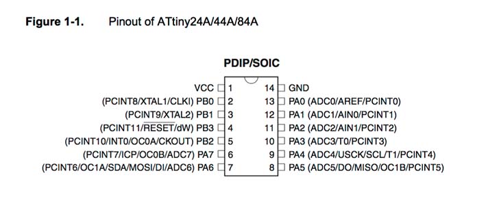
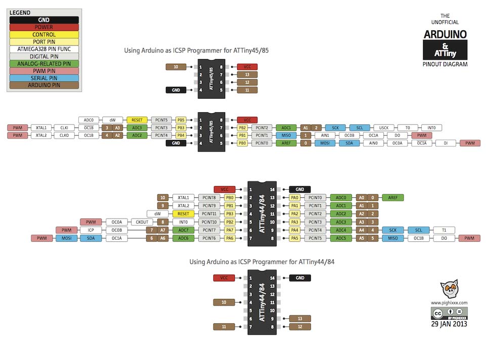
It's super important to look at the pinout diagram, to know exactly what every pin is capable to do, so it's related to the code we will execute on it. This is the diagram for the ATtiny 44, the microcontroller we used on the board we made two weeks ago.
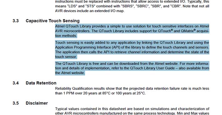
When looking at all the information I saw general information about the capacitive touch sensing that Atmel has developed. I looked for more information and I found really interesting. The have built a free library for people to use and experiment, based on capacitive surfaces that can react to people's interacctions. I might look deep into it to see if I can use it for my final project.
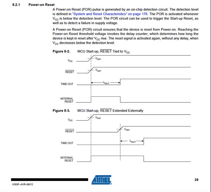
Another interesting thing I found is the capability to reset the microcontroller just with one pin. If I would have known this before I would integrated a reset button on the pin 3, to be able to reboot it if needed.
This week we had an Arduino's class by Guillem Camprodon, which show us the principles and the way of work of Arduino's boards and plattforms.
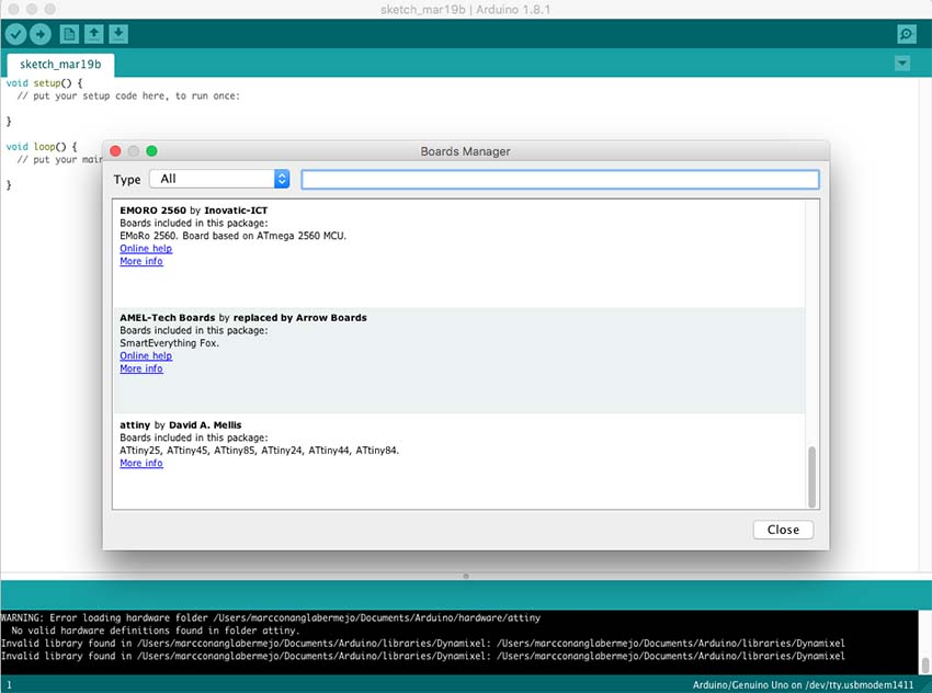
The main purpose was to program our board with Arduino IDE plattform. To do so we first needed to add the Attiny board to it by adding the next url in the program settings: https://raw.githubusercontent.com/damellis/attiny/ide-1.6.x-boards-manager/package_damellis_attiny_index.json
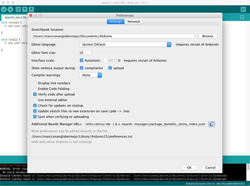
It showed us the boards linked to this url, and by selecting the attiny one we integrated into the program's database.
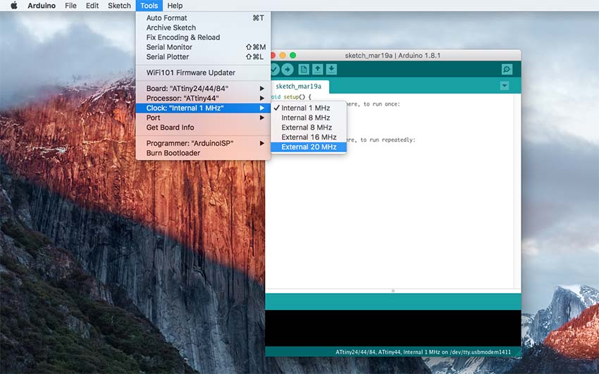
Once this was done we were able to select between the different ATtiny models, and the clock which we are using, (in our case a 20MHz). Then we should select the port were the board is connected and the programmer were are going to be using.
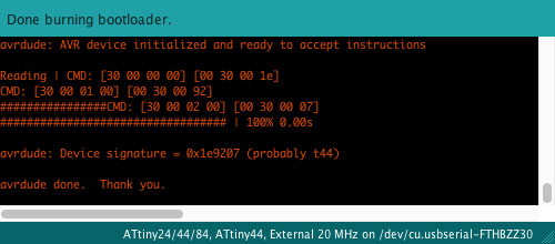
First time we should burn the bootloader, so the microcontroller is set up at 20Mhz, or the clock speed we want.
Ready to program. But first we should check the correspondance list between the ATtiny pins and the Arduino ones, as they are not the same. In my case I had the button connected to the pin number 10 > which corresponds to pin number 3 in Arduino. The LED was connected to number 6 > which corresponds to number 7.
I loaded some example files to try if everything was working well. As you see the pin numbers should be changed accordingly to our connections and its correspondance to Arduino.
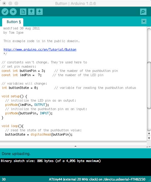
I launched the code below:
const int buttonPin = 3;
const int ledPin =  7;

int button = 0;

void setup() {

  pinMode(ledPin, OUTPUT);
  :
  pinMode(buttonPin, INPUT);
}

void loop() {

  button = digitalRead(buttonPin);

  if (button == HIGH) {

    digitalWrite(ledPin, HIGH);
  } else {

    digitalWrite(ledPin, LOW);
  }
}
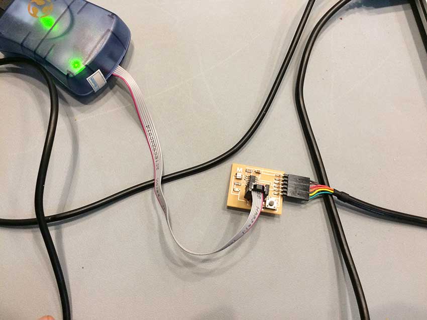
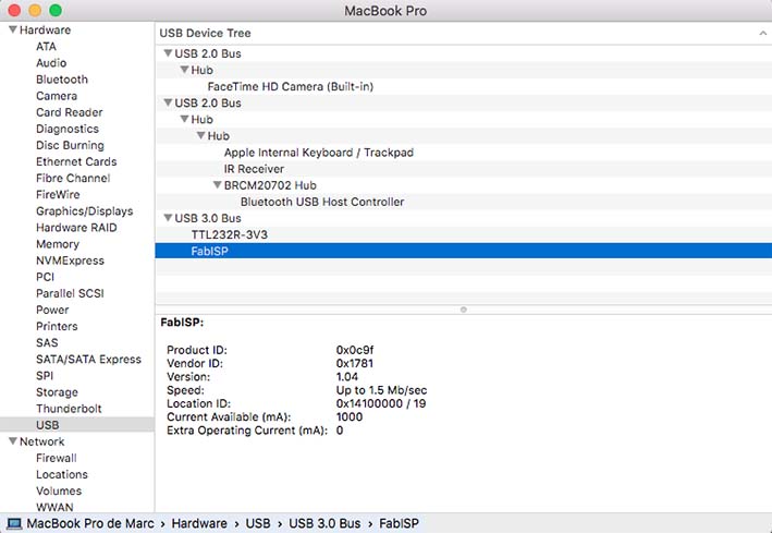
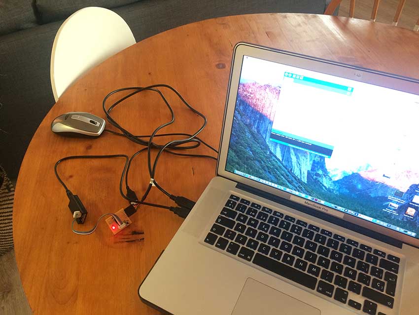
I then used FabISP, and checked first if it was well connected or not on the system information. As you can see below ftdi cable and FabISP appear there, so it means the connections were ok.
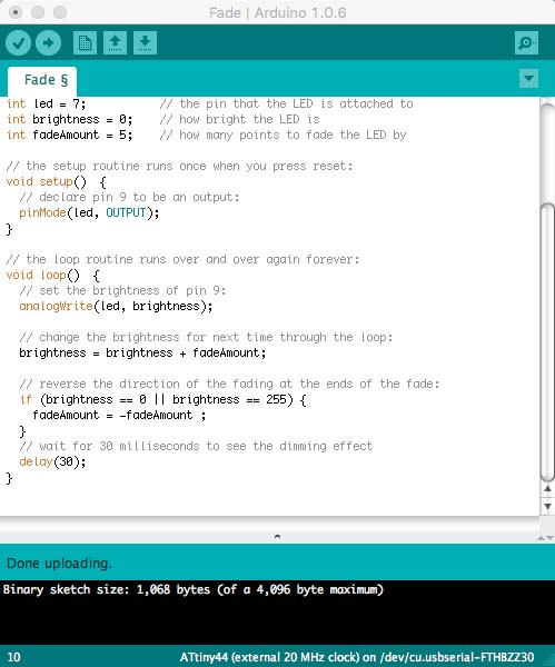
I tried many other codes on the board, as Fade or Debounce, and tried to change few parameters as light intensity, delay, etc to see how many things we were able to configure on such a small board with just a button and a LED.
Connections between FabISP and the board were fine, even though you have to be always careful about the polarity of the components and cables. If you connect them the other way around you might mess it up.
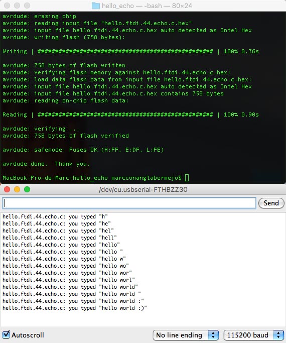
I wanted to try C language this week too so I compiled and uploaded the echo.c.hex to the board. The code basically returns every letter you type on the keyboard, and store it on the microcontroller, so every letter you type goes next to the previous one. I would have liked to test more and actually program in C, but I decided to go further with Arduino and test some things for my final project.
I started testing a 360ª servo, with a pulley I 3D printed some days ago, to see how to program it and the parameters to use. A year back I bought the Arduino's starterkit, so I used it to see a simple exercise based on servos, and then changed it to adapt it to my 360º device.
pass: fab
Few weeks back I had the pleasure to get in contact with Özgür Atmaca, a guy that did a kinetic installation similar to want I want to achieve in FabAcademy, and adviced me not to use hobby servos, as with some time they get easily broken and you can't really rely on them to do this kind of work. Instead he recommended me to use Smart Servos, normally used on robotics, which are more robust and will work very precise. I bought a model called AX-12A which seems to be very convenient for what I would like to do.
I then tried it with Arduino, adding a library specially built for this model.
pass: fab
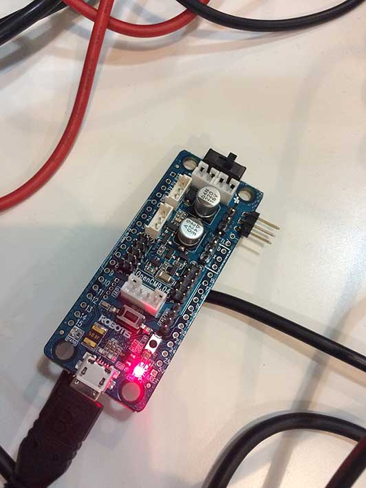
I then found out it would be better to use a specific board called OpenCM9.04 (I bought C model) to control this type of servos, as it can work at 1Mbps, and can read and write at the same time.
I had to do small changes on the board as the AX-12A connectors didn't fit. So I desoldered two connectors and soldered two male three-pins, so that I can easily attach my servos.
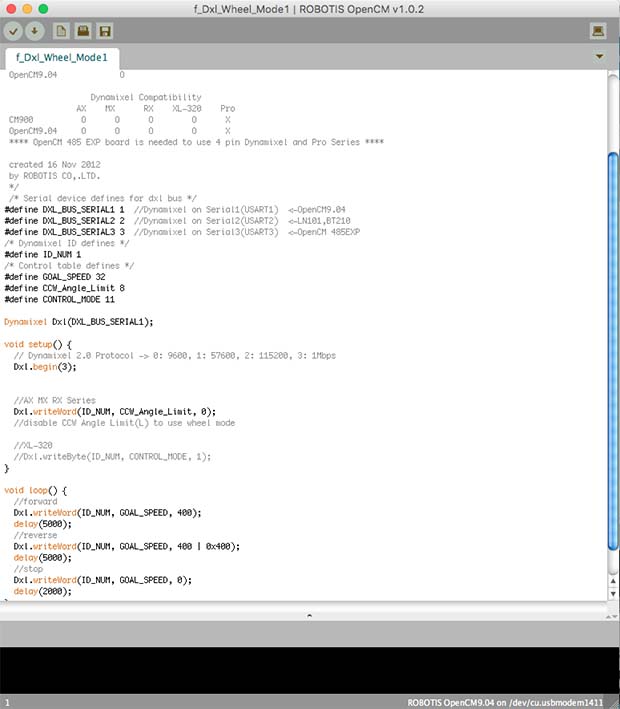
To run the OpenCM9.04 there is a specific OpenSource plattform called the same way, which works on an Arduino's IDE plattform. So it was easy for me to start trying some things it out.
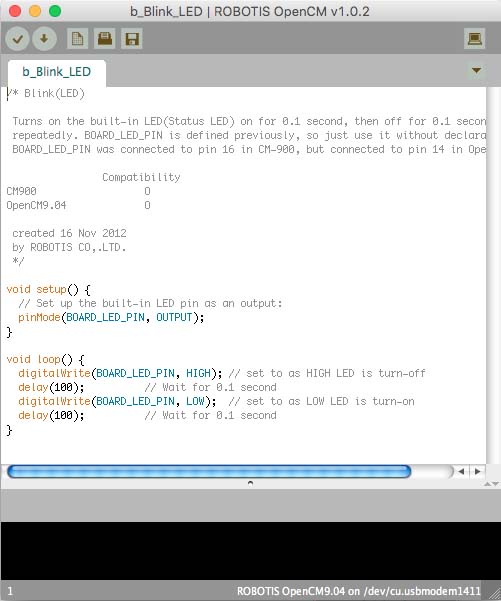
I made all the connections and tried to control the LED attached to the board.
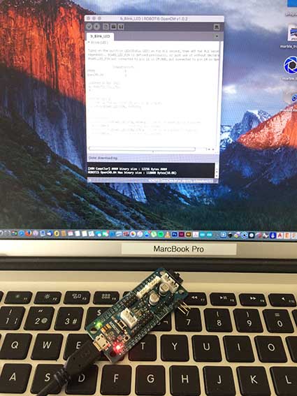
Then tried some specific features to run the servo.
here you can see some video I recorded with all the wiring and some code embeded on the board. I guess this a big step on my project.
pass: fab
Download all the files here