Networking and communications
Week assignment:
· Design and build a wired &/or wireless network connecting at least two processors
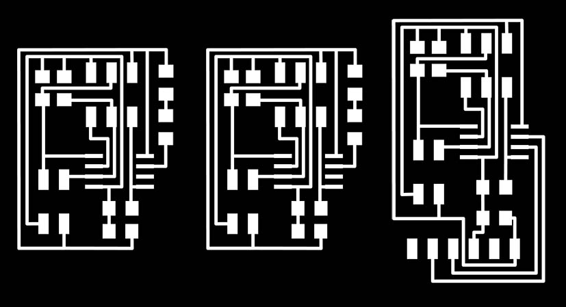
This week was pretty intense as I milled ans soldered almost 8 boards. First I designed 3 boards, to understand and see how serial communication works. Basically there is a master which is the one sending orders, and the slaves (in my case 2 slaves) are the ones receiving them.
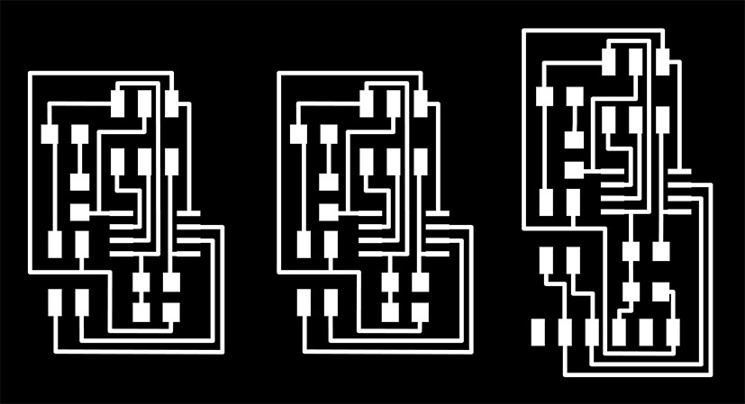
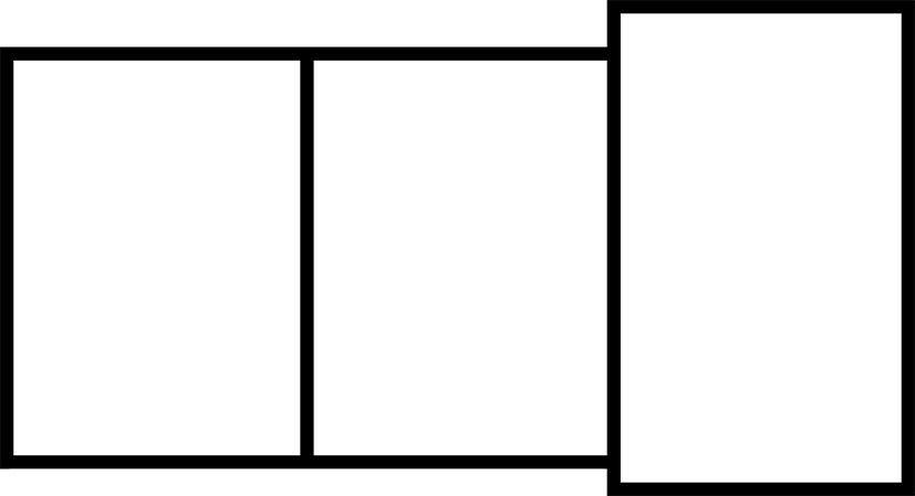
I used same image for the three of them as I wanted to minimize the size of the board and try to optimize the pcb as much as I could.
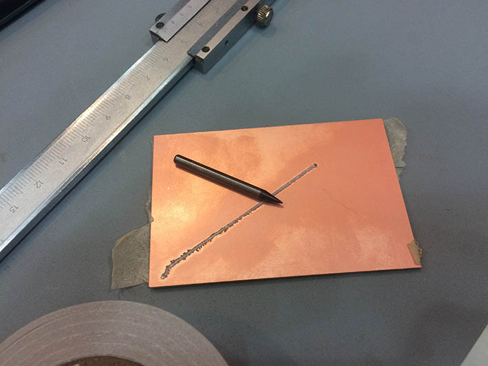
First attempt to mill the board was a disaster. I didn't set up the height of the tool well, and when it started moving from the 0,0 to the first point it scratched all the path and broke the tool :( Sorry Santi and Xavi for that.
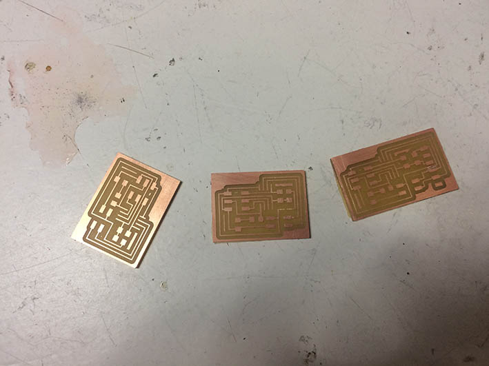
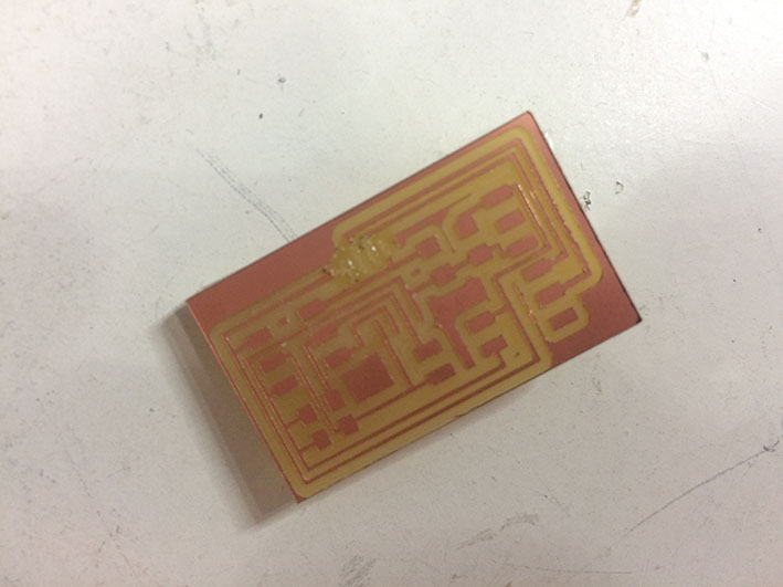
I then milled three more boards. I think you gain a lot of time by milling them all together, as you don't have to be changing the tool every time.
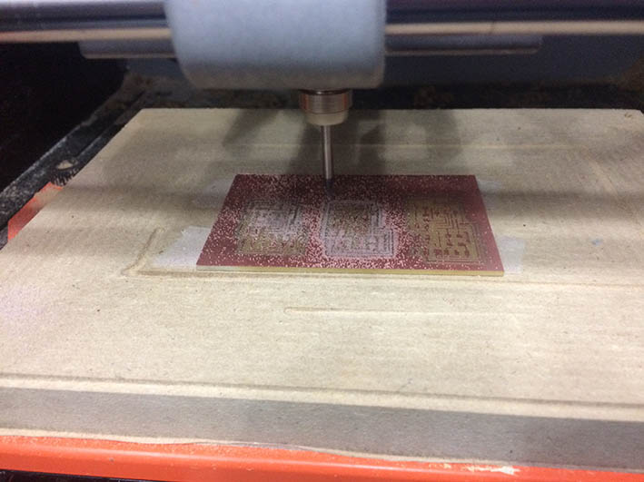
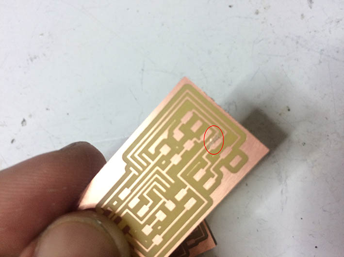
One of them had one path scratched so I had to repeat it again
Finally I had three boards ready to be soldered and programmed.
For each node you have to assign a different number, so that when the master send an instruction to it, it recognizes which one is it. In this case I numbered the master as 0, and slaves as 1 and 2. It is necessary to change the ID in the C code, before uploading it to the microcontroller of the board.

To program it we used make file, as we did in several assignments before. In this case the code is:
sudo make -f hello.bus45.make program-avrisp2
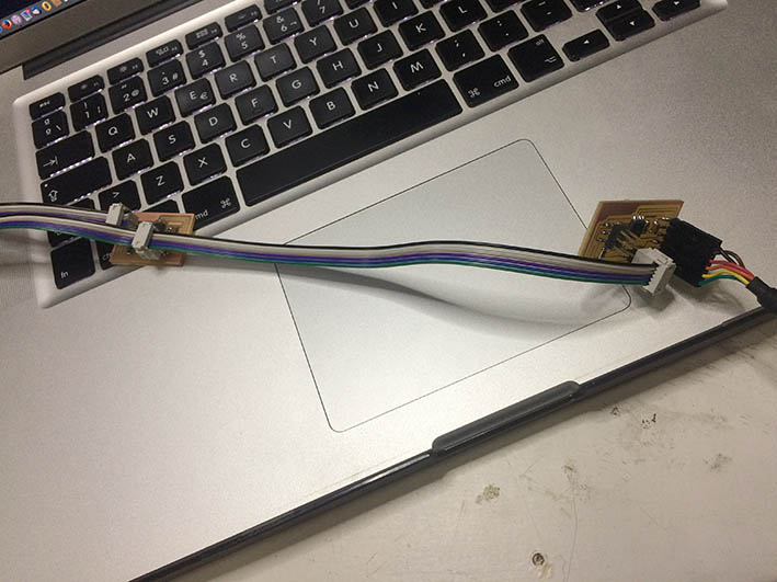
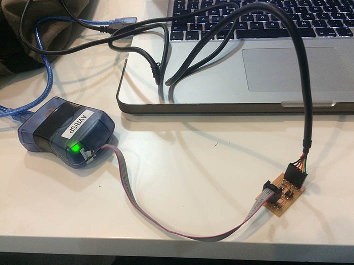
To program the master we used the FTDI cable to give voltage to the board, and the programmer to program it.
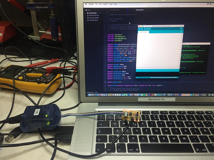
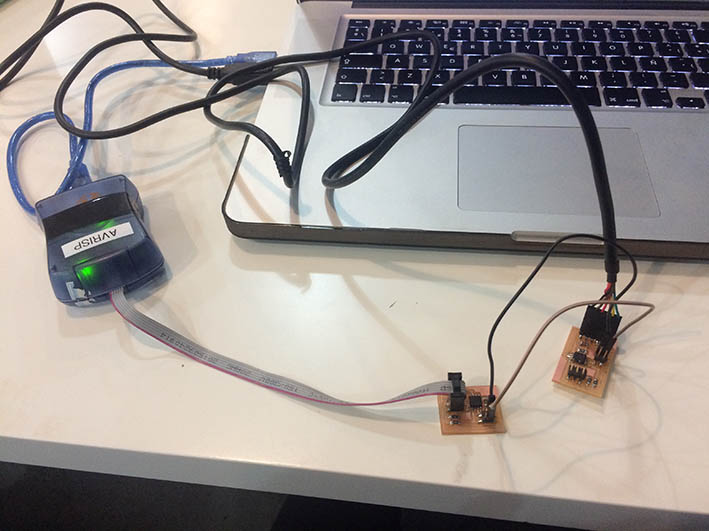
With the nodes, the voltage has to be given by the master, so we need to connect two pins (VCC & GND) from one to the other. At the same time the slave is connected to the programmer.
After being programmed we can open the Arduino IDE and the serial communication (at 9600 baud speed) to write information to the slave and send it to the masters. In this case we should type the number of the slave we want to switch on. For instance, if we type 1 the LED of the board 1 will blink twice. Here you have a video showing how it works
pass: fab
Once I had the serial communication boards ready and working I wanted to try I2C communication. The main difference between I2C and serial is that first one is a synchronous communication. It is mainly used for small distances, and uses just two wires.
I did the design in Eagle, as well as for the serial boards and then generate again the .png for milling them.
I had another issue with a board, which was broken whilst trying to solder a component.
Once I had all of them milled and soldered I tried to program them. The programmer was flashing green which means the connections where good (in theory). So far I achieved to program the master
but couldn't program the slaves. I was using just two wires to power the slave (as I did with the serial communication boards) but didn't work. At the end I realized I was using same code for both protocols and wasn't working. I will recommend future students not to try this protocol unless they know more than the basics. All the research I did was really confuse and the people from previous years that used I2C did it's own code from scratch.
Apart from that, and on the way to continue investigating on my final project, I did some more research on how to communicate between my computer and the servos I will be using, Dynamixel AX-12A.
In week 8 I did already some tests and tried different ways to send data, through Arduino and OpenCM9.04.
This week I have been doing some more research on how to communicate with Arduino but taking advantage of the TTL Half Duplex Asynchronous Serial Communication that the Dynamixel incorporate. This way I can read and write data at 7343bps - 1MBps and have some instant feedback for instance about servos' position, temperature, load, input voltage, etc.
Arduino Uno doesn't support this type of communication natively, so I had to incorporate AX-12 CDS55xx board which makes possible to connect the servos to Arduino controllers.
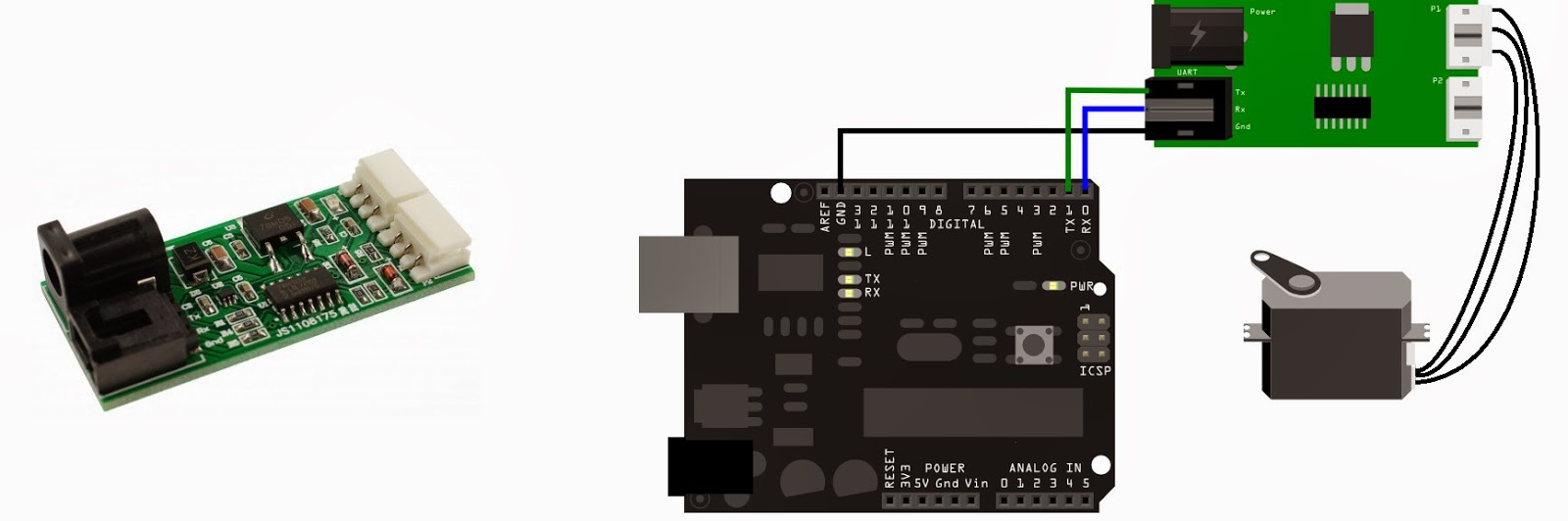
The interface of this driver board just use a UART port (serial port). The board and the servos can be linked by serial bus, so in theory it should be able to connect more than 200 servos. Servos are connected using a Daisy Chain Type Connector between them.
The CDS55xx Driver Board basically integrates a half duplex and a voltage regulator inside. The voltage regulator is meant to manage the power supply, and the half duplex mode means that the transmit wire from the UART is connected to all of the AX-12A servos. This means when you send a command over the wire then all the servos will hear it, but because the message contains the destination servo ID then only one servo, matching that ID number, will process it. If the message requires a response then it is sent back down the same wire from the servo back to the driver board.
This could be also be achieved with a tri-state buffer which could read and write at the same time. 74HC04 and 74HC126 seems to be good for this purpose, as I could see some examples using them.
To try the TTL Half Duplex communication I have used the libraries from Savageelectronics (link here) which has also has several explanations. This is one of the code I used for my tests:
#include DynamixelSerial.h

void setup(){
Dynamixel.begin(1000000,2);  // Inicialize the servo at 1Mbps and Pin Control 2
delay(1000);
}

void loop(){

  Dynamixel.move(3,random(200,800));  // Move the Servo radomly from 200 to 800
  delay(1000);
  Dynamixel.moveSpeed(3,random(200,800),random(200,800));
  delay(2000);
  Dynamixel.setEndless(3,ON);
  Dynamixel.turn(3,RIGTH,1000);
  delay(3000);
  Dynamixel.turn(3,LEFT,1000);
  delay(3000);
  Dynamixel.setEndless(3,OFF);
  Dynamixel.ledStatus(3,ON);
  Dynamixel.moveRW(3,512);
  delay(1000);
  Dynamixel.action();
  Dynamixel.ledStatus(3,OFF);

delay(1000);

}
And here the result of this test, which was satisfactory. This way I will be able to communicate with all my servos through Arduino, using the libraries for read and write, and send commands to them.
pass: fab
Download all the files here