Assignments
As a part of my final project, I wanted to work on bluetooth module as I have to incorporate that in final model.
It is a wireless technology standard for exchanging data over short distances usin short wavelength UHF radio waves in the ISM band and ISM band is basically the range of frequencies ranging from 2.4GHz to 2.485GHz. It was first invented by telecom vendor Ericsson in 1994 and was originally conceived as a wireless alternative to RS-232 data cables
I already have an output board which I wanted to communicate with the bluetooth module. So I didn't milled a new board just used the previous ones and I used all my focus to make communication between multiple boards
Initially I started to work on single board bluetooth communcation with the already built-in mobile app.
Previously I had no knowledge about it so I searched on internet and found an interesting tutorial
I downloaded the android Application from here to send and receive bluetooth data.
Here I am using Arduino just to power up my board.
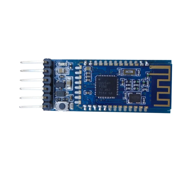
bluetooth module i used
I connected Rx/Tx pins of bluetooth module with Rx/Tx pins of board which were two of pins of FTDI header there and put 9600 baud rate in the program and opened the serial monitor to observe the results using some of the AT commands also. following pictures will demonstart the process step by step
Programming the Module
Checking output on serial monitor
Configuring the AT Commands
Checking the AT Commands Output
Now I just change the configuration of two pins. I connected RX of board to TX of blue tooth module and TX of the board with RX of blue tooth
Checking Results
After this I installed the mobile app to check the bluetooth results
Connecting with bluetooth Module
Sending Data to bluetooth Module
Working of Bluetooth Module
I2C is a type of protocol in which communication and data is shared between different nodes based on a single data bus which is shared between all the nodes in the network.
i2c netowork
I already had 2 boards during weekly assignments (week6 and week10) and I also designed one more PCB which will become the part of my final project
Week 6 Board
Output Circuit Board
After this, I went and milled my final project board and for the checking of the process of networking I tested the i2c connection on it whether its working or not
Main Board
After milling and soldering process I got this result
Soldered Main Board
For the part of programming in i2c, it needs two types of codes, one for the Master and one for the slave. Master is the main board which always takes the decision and the slave follows.
Final Result of i2c communication