
I am using this space for keeping track of steps, links, thoughts and insides of my final project developement. I also want to stablish some workflow tha will allow me to work in a better way.
DIY BIKE POWERMETERS
Keith Hack blog: a full and very detailed review on a DIY bike power meter through a couple of years.
Hack a day: a review on a different aproach to a DIY bike power meter.
Instructables: a a review on a different aproach to a DIY bike power meter.
STRAING GAUGES
All about circuits: a theoretical introduction to strain gauges and the Wheatstone bridge.
Nerdkits: A more practical approach to understanding strain gauges through a hands on project: microcontrolled weight balance.
Sparkfun: how to start with load cell amplifiers.
WEEK 06_
Since I decided my final project I haven't been given too much thought to it. I know what I want to do, but I haven't been able to actually relate my weekly asignments to it yet. I guess that for me to start doing this, first I need to fully understand how it works and set myself some goals and steps to get the most of everyweek work's and aply it to it. I know that further on I will start to work on parallel development, but right now there is an obvious first step which is to understand the theoretical knowledge that lays behind a bike power meter concept. I have found three links on DIY bike power meters, all of them have been being very useful, but there is specially one that has a very detailed documentation on theory bases and steps. This one is Keith Hack's blog. A lot of his blog's entries are dedicated to the process he followed in order to develope his power meter. I found especially illustrating the series of videos he has on the theoretical concepts.
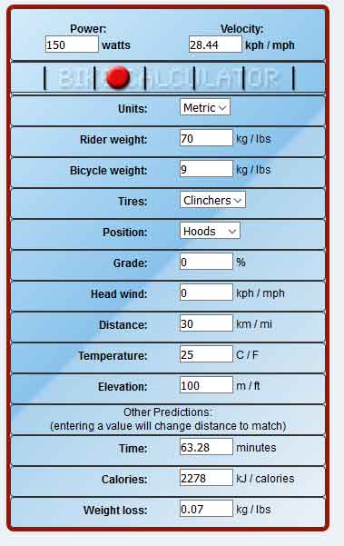
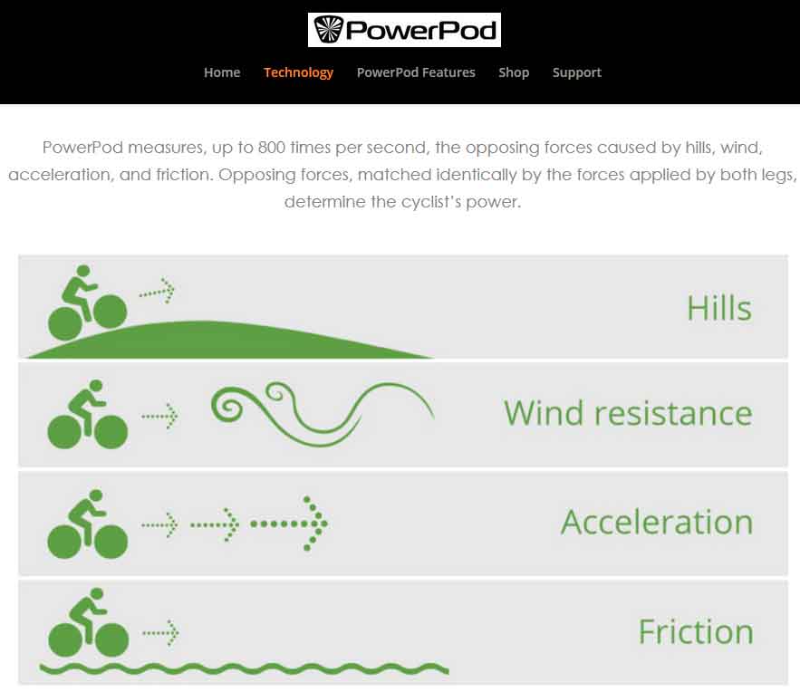
The three major forces that must be overcome to maintain a certain speed are air resistance, rolling resistance, and gravity. There is also some frictional force in the chain, gears, and bearings.The sum of those forces can be multiplied by speed - this is the quantity known as "power". In metric units, we're talking about newtons (a unit of force) times meters/second. It's more common in engineering to use a unit of power that comes from electrical units - watts. The only value out of those three that is easily measure is gravity. For air resistance and rolling resistance there are some formulas that use coeficients for "regular" conditions. As we can see, the calculation od the power by calculating the the other three variables is not simple nor very precise. Wind force, body position, and changing surface profile just make it really hard to keep a real time data estimation. There are tons of internet applications and phone apps, that introducing a bunch of variables and values give you an accurate power measure. Powerpod is a device that is placed on the handlebar and is said it can measure those opposing forces. I am a bit skeptical about the accurateness of those measures even though they have pretty good reviews on DCrainmaker.
The other aproach for cycling power calculation is based on this formula: P = T * w Power equals torque multiplied by angular velocity. Angular velocity is relatively easy to calculate with a magnetic pick-up based on a Hall sensor, or a reed switch. This is the principles that cadence sensors use, the importan thing for the formula to work, is that the angular velocity is on Radians/second, instead of revolutions/seconds as is used for cadence.

The real challenge here is calculating Torque. For this, we need to fully understand how the force transfer works in a bike mechanism to move forward. I have use my bike system model from week 2 to extract a screen shot in order to make some diagrams on future concepts.
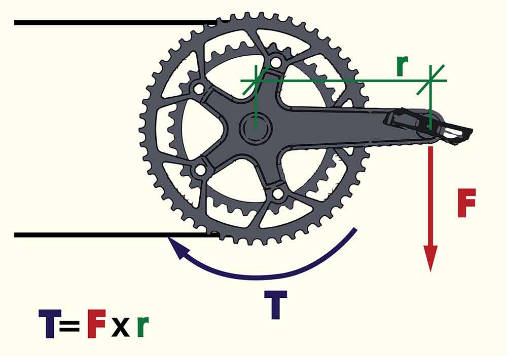
As wikipedia explains torque is a moment " mathematically defined as the cross product of the vector by which the force's application point is offset relative to the fixed suspension point (distance vector) and the force vector, which tends to produce rotational motion." In this case we are talking of the force applied to the pedal by the cyclist (F) and the crank size (r). So the million dollar question is How can we calculate the Force vector? And the question is, with strain gauges. At this point I still don't fully understand how they work, but I am doing an investigation on them and on their application on bike powermeters. Hopefully soon I will have enough information to start playing around with them.
WEEK 08_
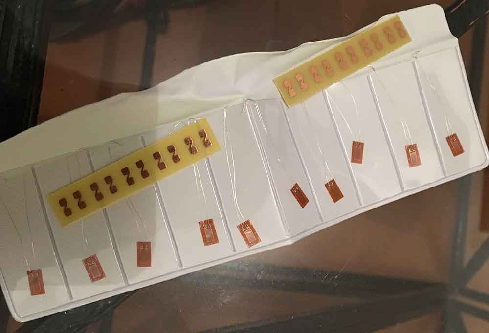
I ordered a few weeks ago some cheap strain gauges to China, to start playing around. I am sure that one of the keys for the precision of the system is the quality of the gauges. I just though before investing on some very precise gauges, better first use crappy ones untill I fully understand how they work. They finally arrived this week and I am very excited about it!! I know it might take me still a couple weeks to have time to fully engage with them, as right now we are very busy with the machine asignment. I just order a Load Cell Amplifier HX711, which I am starting to study and hopefully by the time it arrives, I will be able to start messing around with it.
WEEK 10_OUTPUT
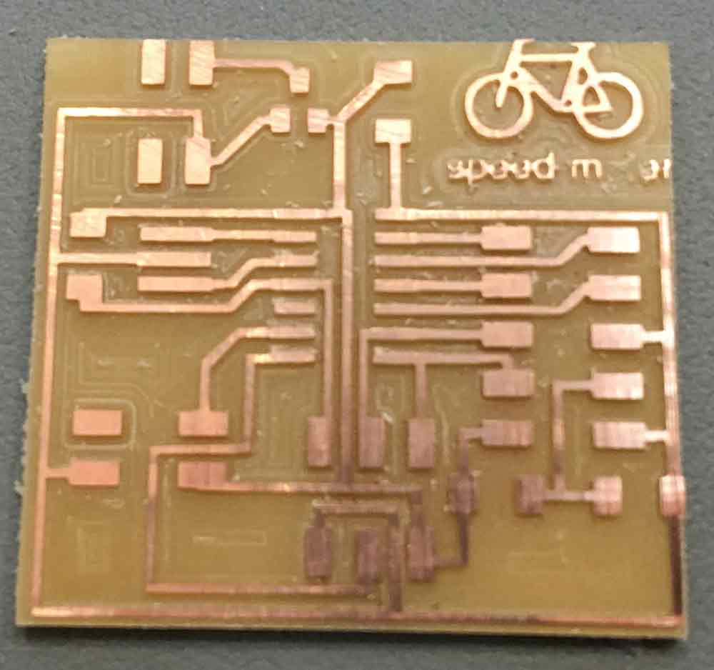
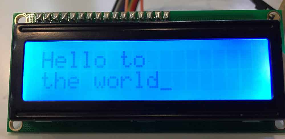
For my output assignment I decided I wanted to use an LCD screen. I will be using a display for my final project and this is the easiest one to start. I also wanted to do an integrated exercice with input asignment week, so I decided to do an speedmeter. This works with a hall sensor, and it is one of the options I have on mind to calculate angular speed of the pedal. I made a board with the pins ready to connect an external shield with a hall sensor. The idea is:

To see the whole process I followed, you can go to that week assignment page. But basically I managed to make a PCB with the waiting pins for a sensor and the pins for an LCD and I used Neil's program to test it.
WEEK 11_
Adhesive! It is a cruzial part for the succes of any straing gauges system. Using adhesive is the most common way of fixing strain gauges. The quality of the union has to be enought to asure the deformation tranfer to the gauges. Strain gauges can be applied using cold or hot curing adhesives. In experimental stress analysis, fast-acting adhesives (superglues) are commonly used as they cure very rapidly at room temperature. The components being bonded must be carefully cleaned to eliminate dirt, grease, and oxide layers. Thorough preparation is a basic requirement to achieve good adhesion. After having check the specialized glues, I found out most of them are made out of cianoacrilic, which basically is superglue. So, for my starting experience that is what I will use! I watch tons of videos on how to glue strain gauges, this is one of them:
WEEK 13_INPUT
My input assignment was the continuation of output week's assignment. I made a tiny board just to solder the hall sensor and connected it to my previous board. I used a code I found and after having reviewed and made the right changes, I was able to get the speed and distance on my LCD. Still not very happy with the performance of the hall sensor as even using neodimiun magnets they have to be super close to the sensor to get a reading. Starting to consider it might not be the best option for angular speed calculation.
To see the whole process I followed, you can go to that week's assignment page. But I managed to read the wheel spinning and get an speed and distance on the LCD screen.
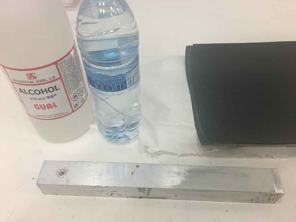
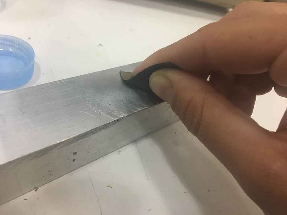
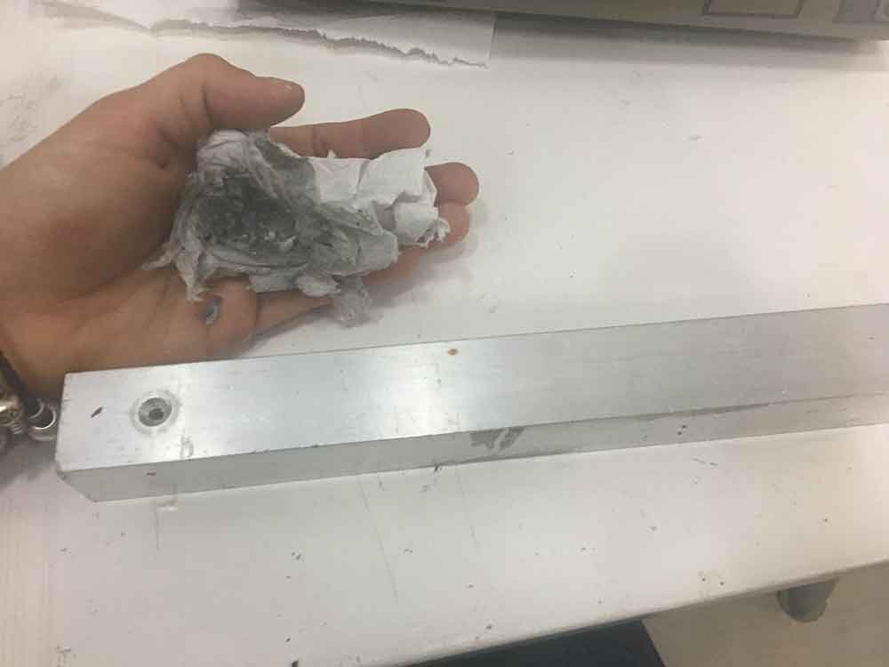
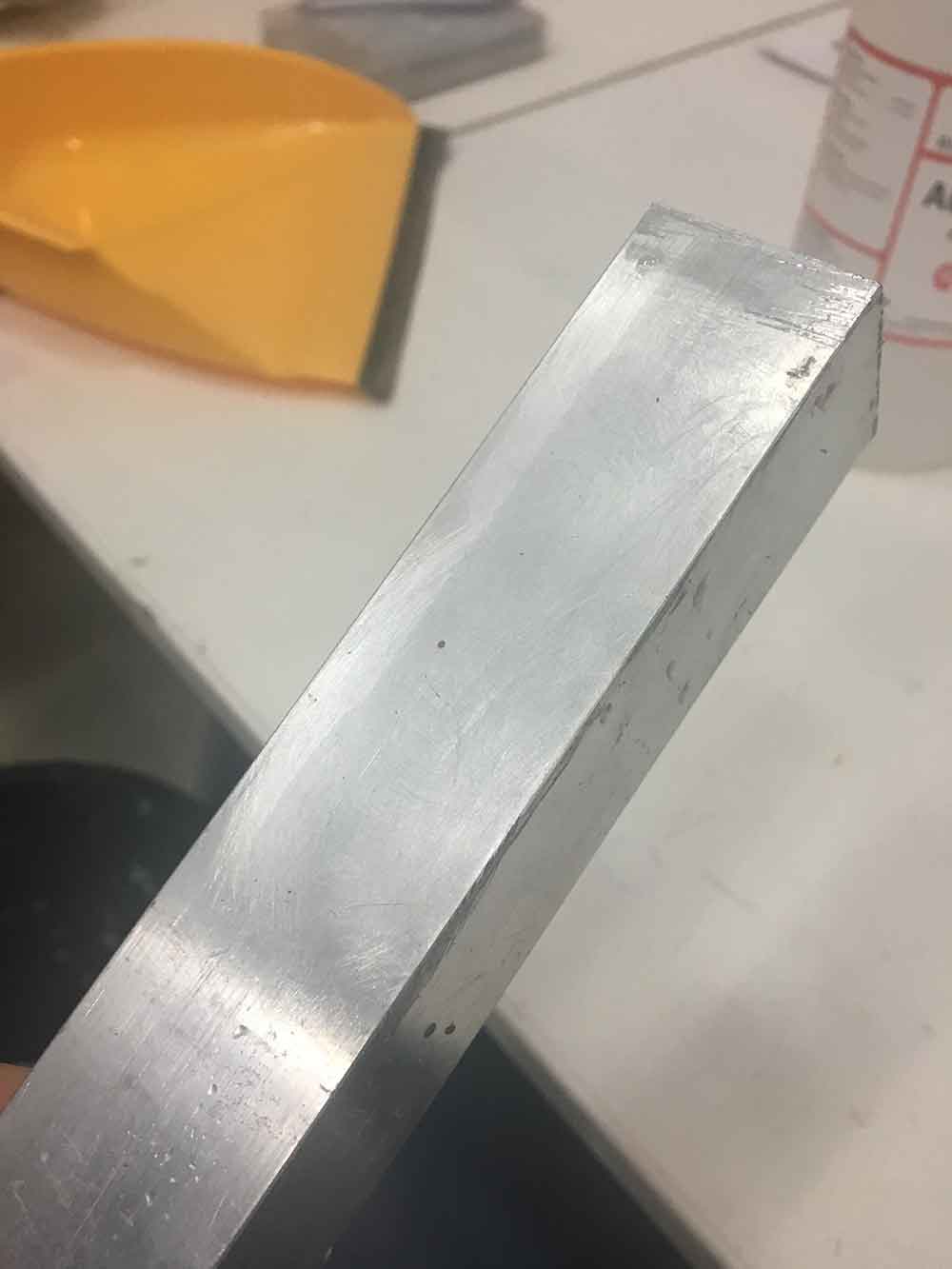
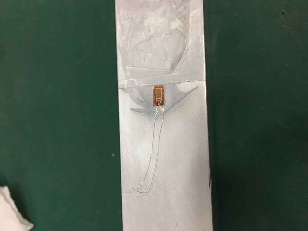
I have realised I will probably not use an LCD screen for my final project as it need 10 pins, and I am not very satisfied with the display options. I will probably use an OLED screen, which used 4 pins and there are also lots of libraries for it. It was during this week where I also started experimenting with my chinese strain gauges. I followed the several videos on how to install them. I first cleaned the surface well with alcohol and sand it with 400 grid, 600 grid and finally with 1000 grid. I marked with tpe where my gauges were going to be, tape them down with transparen tape. This allows you to pull the strain gauge from the surface to put some super glue and put the gauge back and press.
WEEK 15_NETWORK COMUNICATION
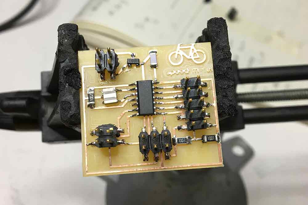
I did a pcb with a ATtiny 85 to run a Oled module and a bluetooth hc-sh 08. The goal is to receive the power data and other parameters via bluetooth from the nRF52832. For the networks and communication asignment what I dis is send a string trhough my phone and have it displayed on the Oled screen. I had loads of trouble with the code, as I had to find a very small Oled library to fit in the 8 kb of memory of the ATtiny 85 with the serial library. The one I found was a library that mixed arduino code with C. As I don't really understand C code, it took me a while to fix the problems I encountered. At the end I managed to work!
This week I also started to work with the nRF52832 sparkfun board. It is a very interesting board as it is both a microcontrolloer and a bluetooth and ant+ radiotransmiter. This will be the brain of my sistem. Sparkfun has a complete guide on how to start working with it. It is a good board to work with for me, because it comes pre-programmed with a serial boothloader and it works with Arduino Idle, this makes programming easier for me. To get the board into the boothloader mode is a little tricky as you have to press both the reset and the pin 6 button at the same time, but once you got it is fairly simple. I managed to load the blink arduino example to the board.
WEEK 17_
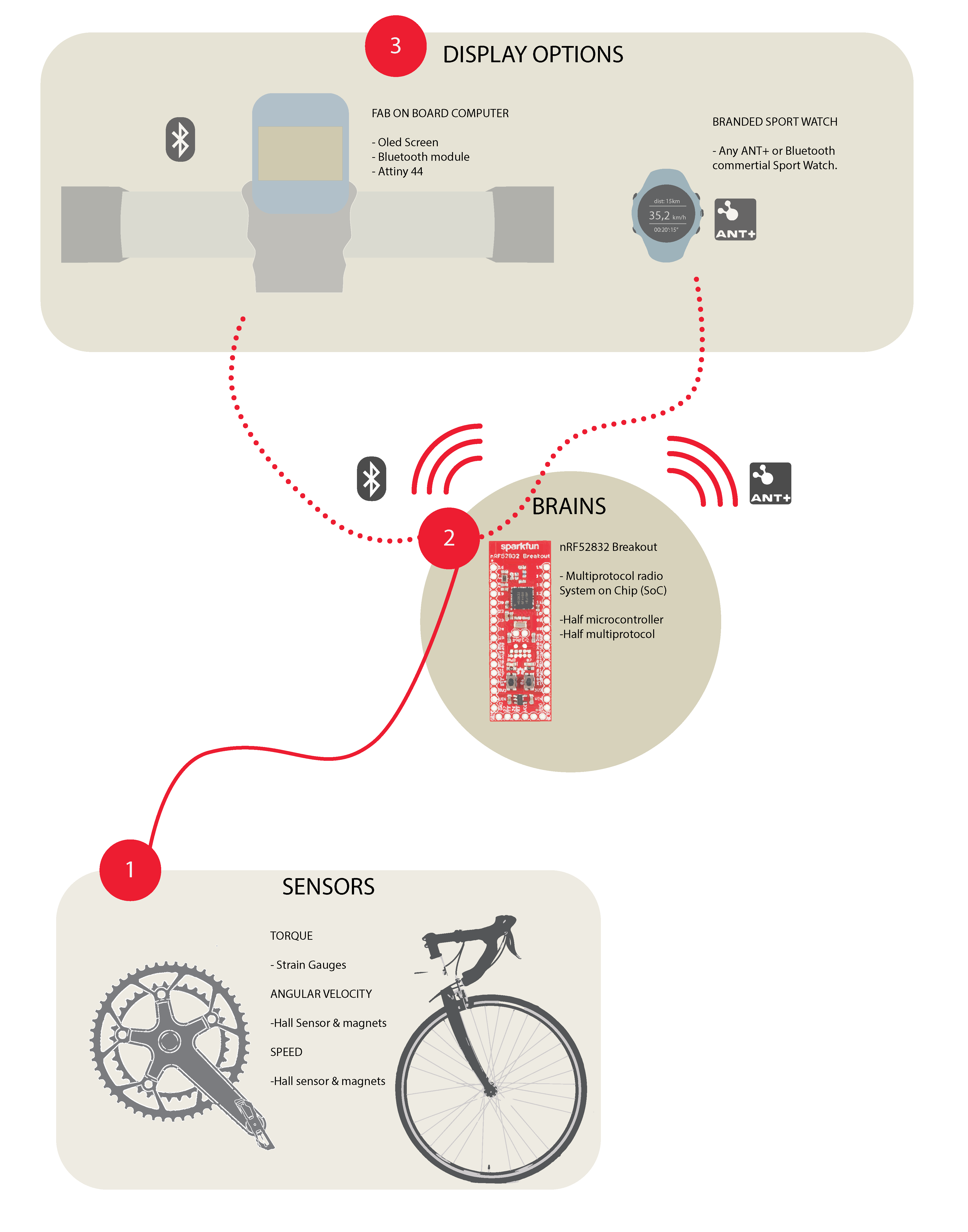
This week was time to get the system working. I did a diagram on how the system should work, to clarify my ideas.

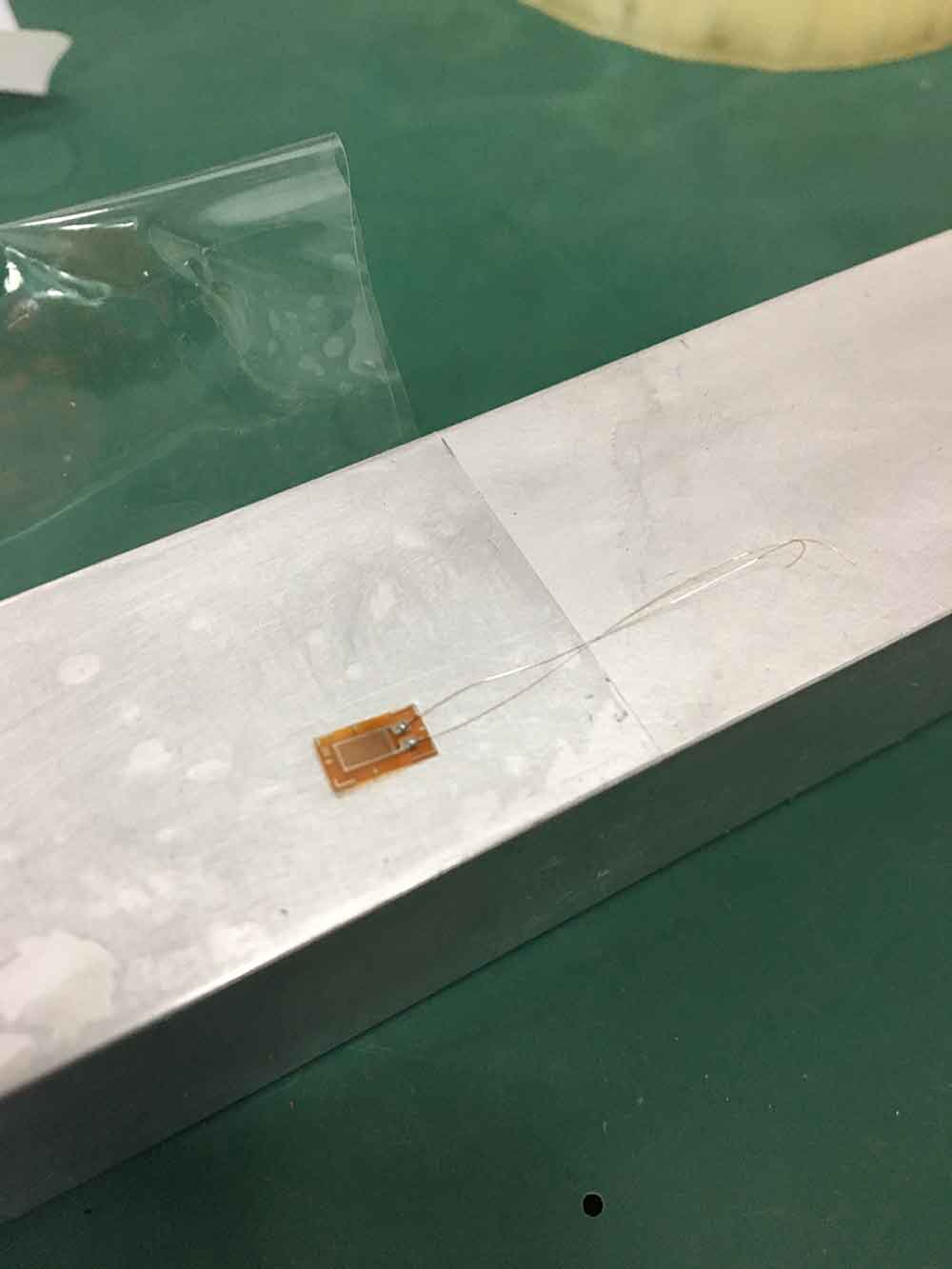
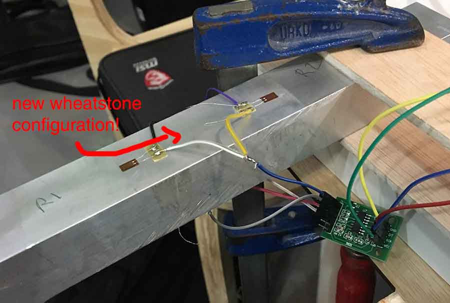
I glued two more strain gauges to the aluminium bar. I also milled a pcb with the pads to connect the gauges as a wheatstone bridge.
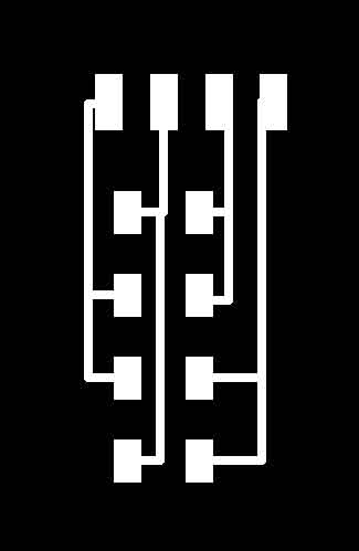
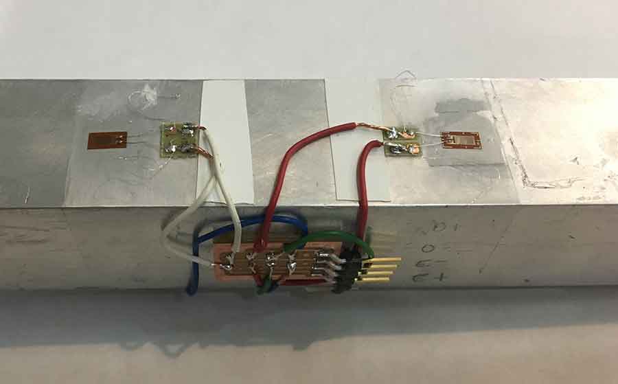
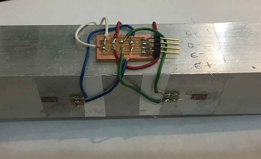
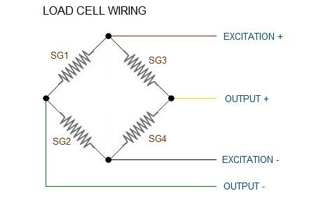
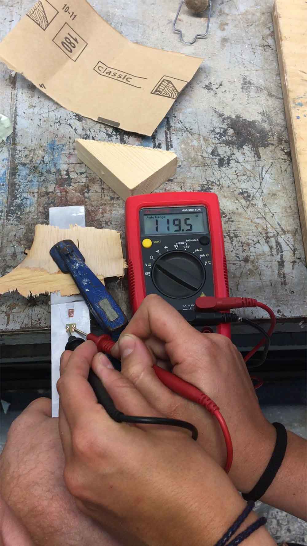
When the aluminium bar deflects due to a force, the resistance of the strain gauges will varies. This variation will be super tiny, they are ususally around the 0.1 Ohms. The wheatstone bridge is a configuration of four resistors with a known voltage applied, it is a good way of turning small changes on resistance into something more measurable. This changes are still very small, so I have used an amplifier. I have used the HX711, which is specific for load cell uses. This connects directly to Arduino pins and has various libraries to help get these measures.

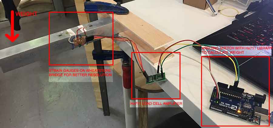
For some reason once I charged the sketch my system din't get any reading. I checked all connections and though that the only place where it could be a problem was on the wheatstone bridge assembly. So I changed to a more shabby way of cannecting it. Surprisingly with this method I was able to calibrate the system and get real time readings. Calibration wasn't done super accurately and the system still have tons of noise, but it was a very sweet way of endind the day!! :)
WEEK 18_
This week I realized my initial spiral development was too ambitious. I wanted to use a board I don’t fully understand and as time is running out I decided to get rid of the Nrf52832 and use an Arduino Nano with a Bluetooth module on master role to communicate with the other module on slave role that will receive the data to display on the oled screen. I wanted to use the ant + communication as it is the protocol that almost every sport watch uses and I think integration is crucial, but realized it was better to have Bluetooth communication that nothing.
I started pairing the Bluetooth modules. To do that I check a lot of webpages, but none of them actual paired the hc-sh 08. Mostly they use sh 05 and 06, the AT commands are a little bit different. Searching the internet, I found that it was almost the same as the SH 10, so I found a documentation for Network Communication that used this last one. I followed it to pair them.
BACK HOME <<<