Made your slide: 1280 x 1024 pixels with your name, project name, Fab Lab name, a photo/render/sketch of your project, a brief description of what your project is/does.
Made a ~1 minute (10MB/1080p/720p) video of you explaining your project.
Made a separate Final Project page that briefly summarises your project.
Included the BOM (Bill of Materials) for your project.
Linked from this page to any weeks that you worked on your final project.
Linked to your presentation.png and presentation.mp4.
Included all of your original design files in the archive (2D & 3D, board files & code) No external hosting of final project files - discuss file sizes with your instructor.
Included the licence you chose.
Acknowledged work done by others.

This is a step by step process on how to replicate my final project.
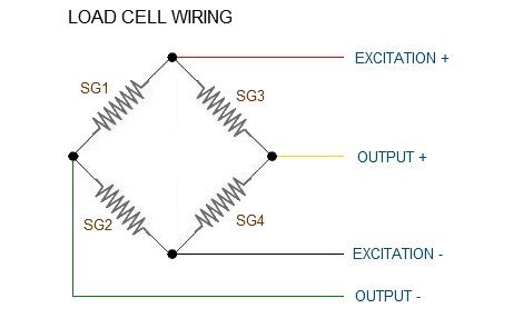
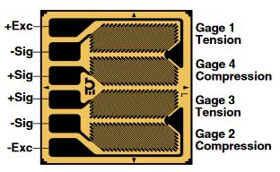
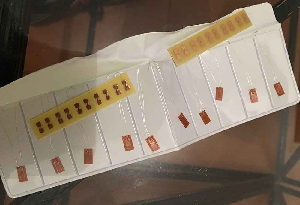
-Strain gauges: I used this 2 half bridges on one carrier from Omega. They are 350 Ohms with a 2.13 Gauge value. Any Strain Gauge can be used, as long as they are assembled as a wheatstone bridge, this one allowed me to do the Wheatstone without almost any wire, which is better on terms of noise and layout on the crank.
-Wheatstone bridge configuration pads:
-HX711 Load cell amplifier:
-Arduino nano:
-sh-hc 08 Bluetooth Module on master role:
-7.4 Lipo Battery:
-Acrilic:
-Oled screen module:
-Sh-hc 08 Bluetooth Module on slave role:
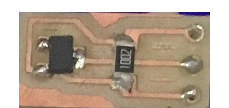
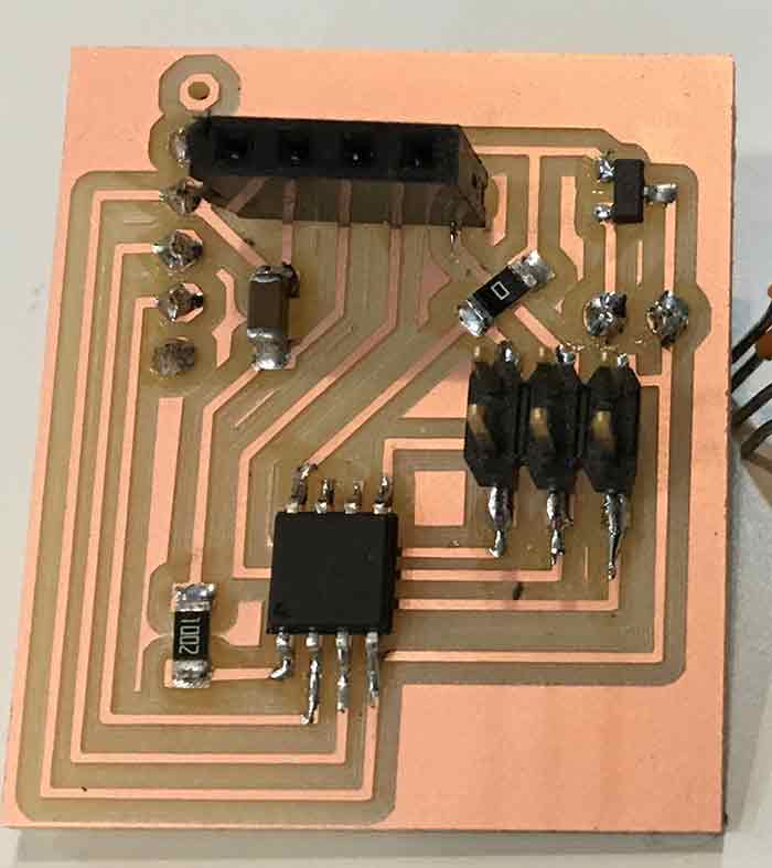
-ATtiny 85 pcb: ATtiny 85, 10 K resistor, 1uF Capacitator, 0 Omhs resistor, 5 v voltage regulator, 3x2 pin male header,2x1 female header, 6x1 female header,4x1 female header.
-7.4 Lipo Battery:
_INPUT
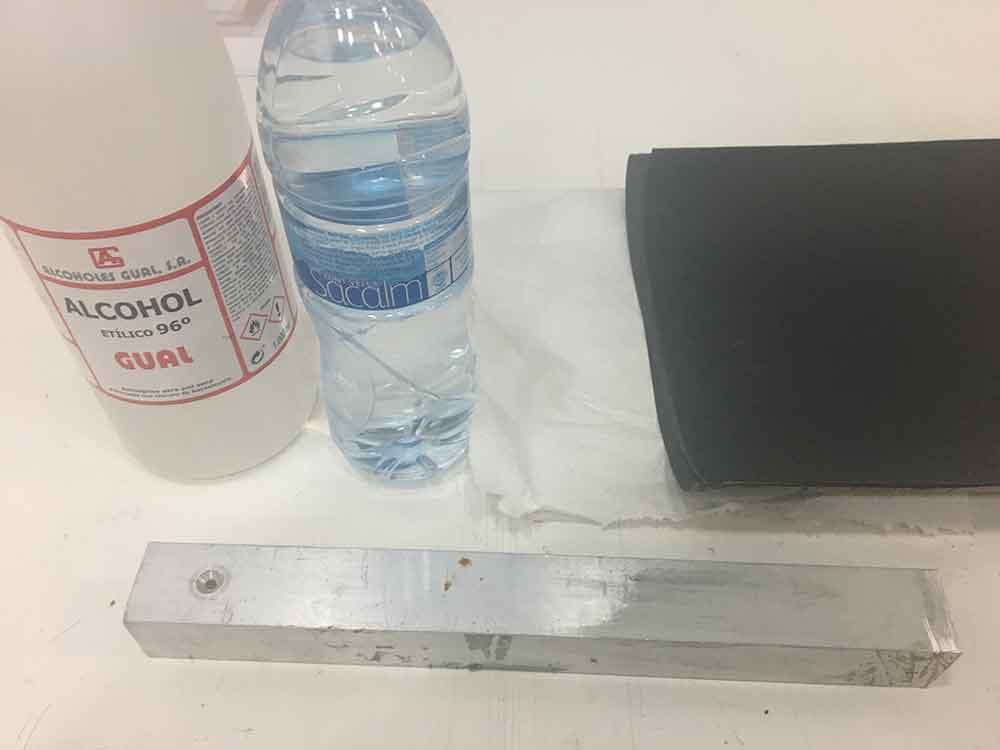
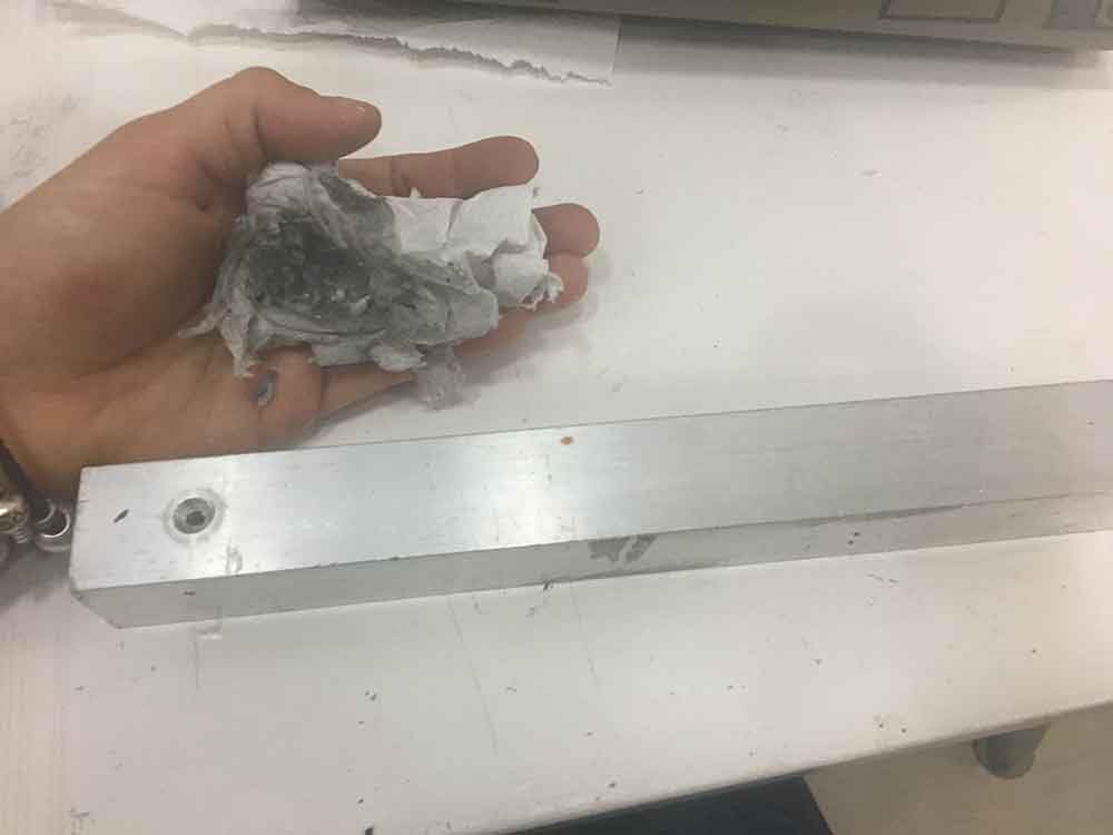
As an input I used Strain Gauges. I started experimenting with some cheap chinese strain gauges. The first step is to install them on the surface we want to meassure. For this there is an cruzial part: Adhesive! The quality of the union has to be enought to assure the deformation transfer from the surface to the gauges. Strain gauges can be applied using cold or hot curing adhesives. In experimental stress analysis, fast-acting adhesives (superglues) are commonly used as they cure very rapidly at room temperature. The components being bonded must be carefully cleaned to eliminate dirt, grease, and oxide layers. Thorough preparation is a basic requirement to achieve good adhesion. After having check the specialized glues, I found out most of them are made out of cianoacrilic, which basically is superglue. So, for my starting experience that is what I used. But for the final configuration I used an specific cianocrilic for strain gauges. Loctite 315. I watch tons of videos on how to glue strain gauges, this is one of them:
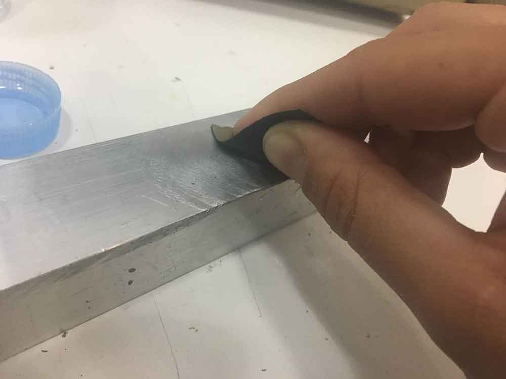
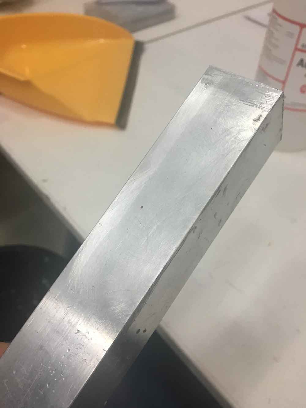
Following the tutorial, I first cleaned the surface well with alcohol and sand it with 400 grid, 600 grid and finally with 1000 grid. I marked with tpe where my gauges were going to be, tape them down with transparen tape. This allows you to pull the strain gauge from the surface to put some super glue and put the gauge back and press.
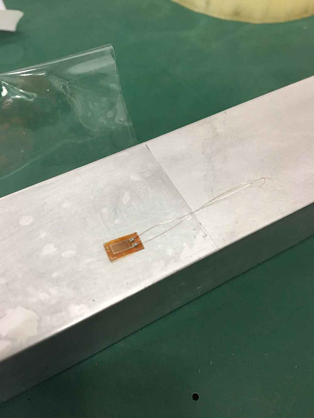
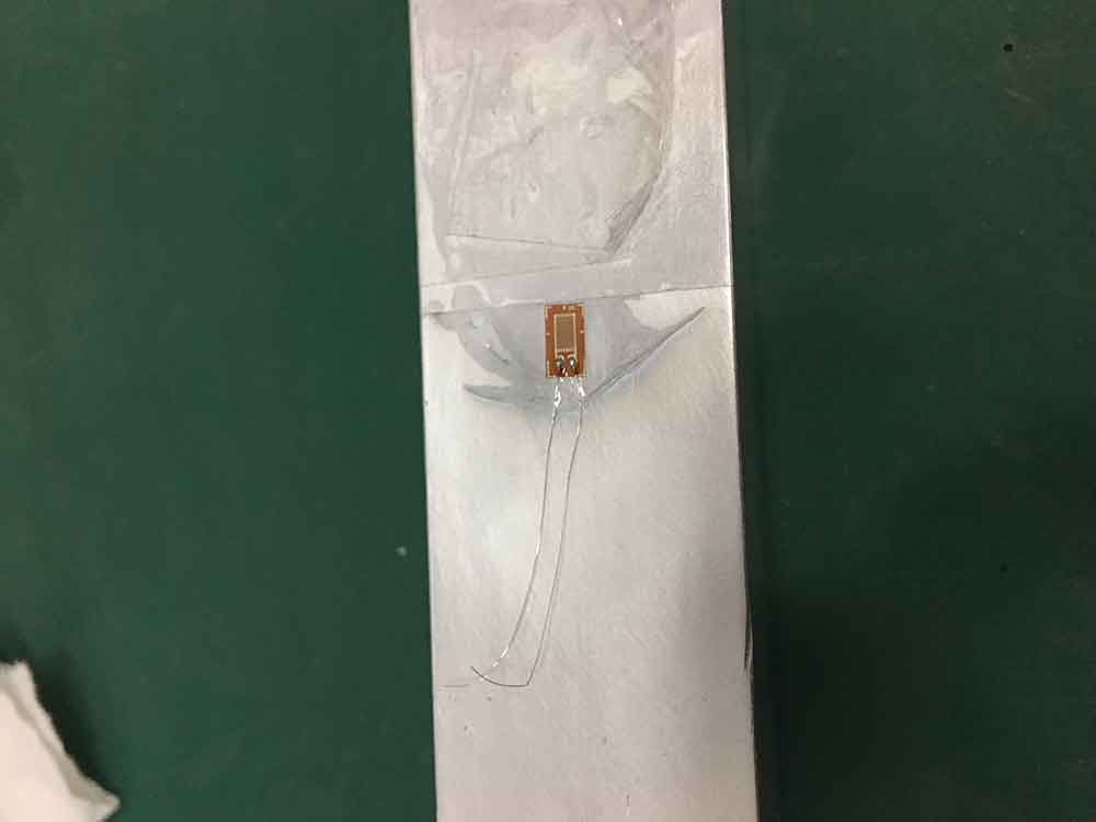
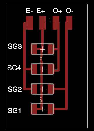
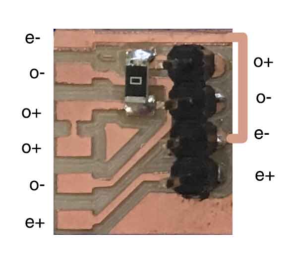
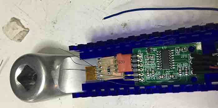
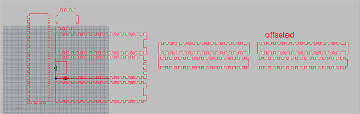
Once the strain gauges are installed is time to connect them as a wheatstone bridge. To do this I dis a wheatstone bridge configuration pads on eagle and milled them with the ronland machine.
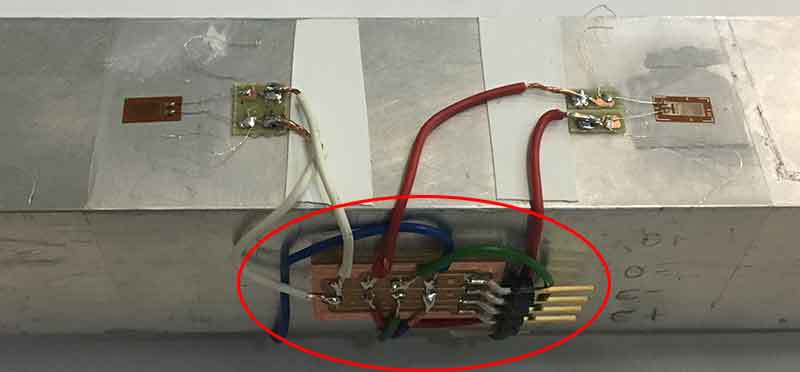
Those pads are meant for using 4 individual strain gauges. As you can see the configuration looks very messy with all those cables. Fortunately, I found this Omega Gauges, that are two half bridges on a single carrier. This means that from 8 cables from the gauges, is reduced to 6, with a very neat configuration. Still I did a wheatstone bridge pad configuration to get rid of the cables as much as possible.
Even the result looks better with this last gauges, the device can be built with any of them.
For reading the strain gauges I used a load cell amplifier. I used a breakout board with a HX711 chip. This chip is a 24 bits ADC. When there is a deflection on the crank the strain gauges resistance value varies. The whole system relies on being able to sense that change of resistance. The Wheatstone bridge is a configuration that amplifies the readings but is not enough. During my investigation, I found that the easiest and cheapest way to amplify the lecture of the gauges is by using an HX711 chip. It also has a bunch of libraries that make it easier to work with the data and transform them to force values. I used a commercial breakout board as finding the chips on its own is harder that what it could seem. This board is a link between the gauges and the Arduino. The idea would be to end up having a board that includes the microprocessor, the amplifier and, why not? the Bluetooth master.


I also used a hall effect sensor as an input for my final project. I used it also during input device week. That time I used it to calculate speed and distance with an speedometer. This time I needed to use it for calculating angular velocity. The main difference now I need the velocity in radians/second instead of km/h. I used the second version of the hall effect sensor that I make for taht week.
_OUTPUT
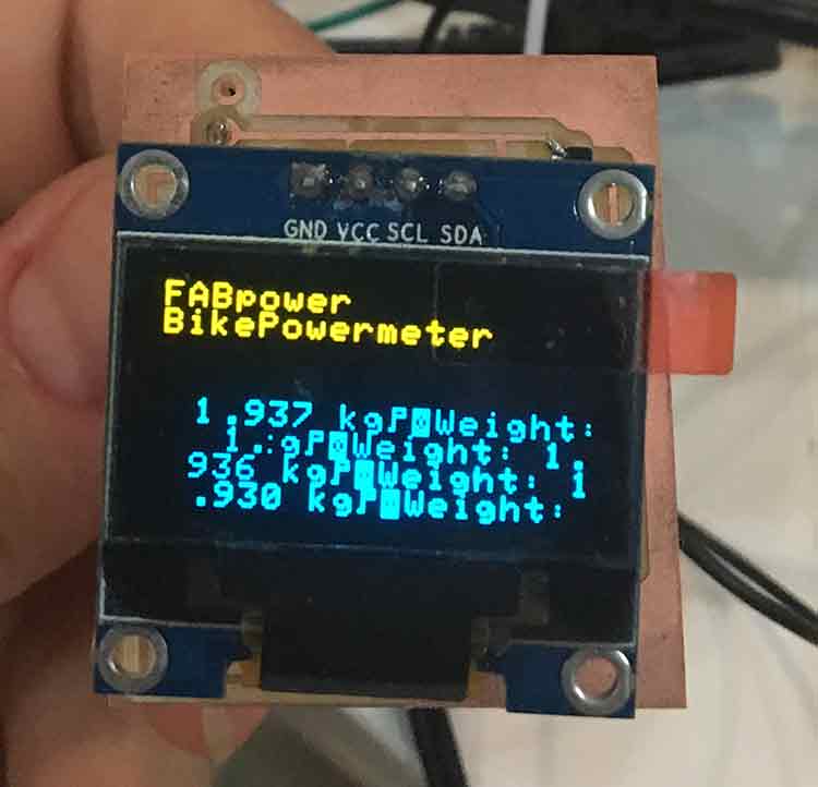
I did a pcb with a ATtiny 85 to run a Oled module and a bluetooth hc-sh 08. I decided to use the Oled Screen Module as an output because is smaller (maybe a little too small) and it works with I2C, which means I only needed 4 pins instead of the 8 you need with an LCD screen. That is the reason I could pass with an ATtiny 85 and didn't need an 84. The reason to jump to eighties was a memory issue. I made this board during week 15 on Network Communication week, you can see all the trouble I encounter with it on that week's webpage. At the end, I ended up with a fairly simple board, as any pull-up/ pull-down resistors for the modules were included on themselves. I tried to have the most compact pcb in order to have a relatively small display device at the end. This was important considering how tiny the oled screen is. I didn’t want to have a huge element for a small screen.
_NETWORK COMUNICATION
Communication, in my case was, very important. I needed a wireless comunication between the crank and the screen on the handle. I wanted to have both bluetooth and ant+ comunication, but I ended up sticking jus with Bluetooth. At least for the moment. For the networks and communication asignment I sent strings trhough my phone to the Oled screen.
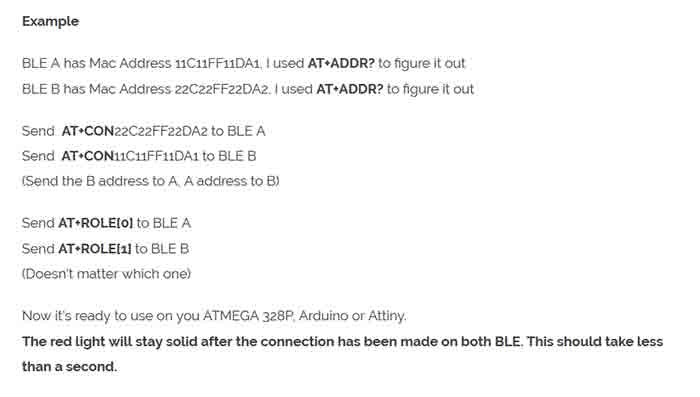
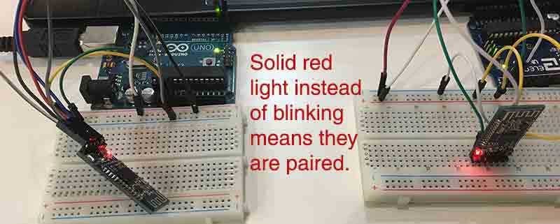
But for the final project what I needed was to pair two Bluetooth modules and have one of them sending information while the other receives.I started pairing the Bluetooth modules. To do that I check a lot of webpages, but none of them actual paired the hc-sh 08. Mostly they use sh 05 and 06, the AT commands are a little bit different. Searching the internet, I found that it was almost the same as the SH 10, so I found a on Dan Chen's documentation for Network Communication some usefull information on this last one. I followed it to pair them.
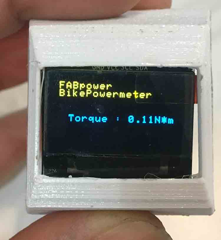
I got loads of trouble to get data displayed on the screen via bluetooth, but at the end I realized it was not a bluetooth problem, it was a disincronization of the delays on the emiting code and the receiving code. Once the delays were syncronized I started to send values from an arduino to my ATtiny 85 with Oled screen module.
For the code, I have several things going on. All my programming have been made on Arduino. The first thing when using strain gauges is to calibrate them. The strain gauges glued to a metalic bar, or a bike crank, works very similar as a load cell. You need to calibrate them. For this the HX711 library includes a code that has to be run once the gauges are glued while the crack is atached to its final position. We can detach it again later for finishin the assembly, but for calibrating purposes this has to be done in ti final position.
 #include
/*#include
SoftwareSerial Serial(26,27); // RX | TX*/
/*
 * circuits4you.com
 * 2016 November 25
 * Load Cell HX711 Module Interface with Arduino to measure weight in Kgs
 Arduino
 pin
 2 -> HX711 CLK
 3 -> DOUT
 5V -> VCC
 GND -> GND

 Most any pin on the Arduino Uno will be compatible with DOUT/CLK.
 The HX711 board can be powered from 2.7V to 5V so the Arduino 5V power should be fine.
*/

#include "HX711.h"  //You must have this library in your arduino library folder

#define DOUT  3
#define CLK  2

HX711 scale(DOUT, CLK);

//Change this calibration factor as per your load cell once it is found you many need to vary it in thousands
float calibration_factor = 800; // worked for my 40Kg max scale setup

//=============================================================================================
//                         SETUP
//=============================================================================================
void setup() {
  Serial.begin(9600);
  Serial.println("HX711 Calibration");
  Serial.println("Remove all weight from scale");
  Serial.println("After readings begin, place known weight on scale");
  Serial.println("Press a,s,d,f to increase calibration factor by 10,100,1000,10000 respectively");
  Serial.println("Press z,x,c,v to decrease calibration factor by 10,100,1000,10000 respectively");
  Serial.println("Press t for tare");
  scale.set_scale();
  scale.tare(); //Reset the scale to 0

  long zero_factor = scale.read_average(); //Get a baseline reading
  Serial.print("Zero factor: "); //This can be used to remove the need to tare the scale. Useful in permanent scale projects.
  Serial.println(zero_factor);
}

//=============================================================================================
//                         LOOP
//=============================================================================================
void loop() {

  scale.set_scale(calibration_factor); //Adjust to this calibration factor

  Serial.print("Reading: ");
  Serial.print(scale.get_units(), 3);
  Serial.print(" kg"); //Change this to kg and re-adjust the calibration factor if you follow SI units like a sane person
  Serial.print(" calibration_factor: ");
  Serial.print(calibration_factor);
  Serial.println();

  if(Serial.available())
  {
    char temp = Serial.read();
    if(temp == '+' || temp == 'a')
      calibration_factor += 10;
    else if(temp == '-' || temp == 'z')
      calibration_factor -= 10;
    else if(temp == 's')
      calibration_factor += 100;
    else if(temp == 'x')
      calibration_factor -= 100;
    else if(temp == 'd')
      calibration_factor += 1000;
    else if(temp == 'c')
      calibration_factor -= 1000;
    else if(temp == 'f')
      calibration_factor += 10000;
    else if(temp == 'v')
      calibration_factor -= 10000;
    else if(temp == 't')
      scale.tare();  //Reset the scale to zero
  }
  // delay (1000);
}
//=============================================================================================
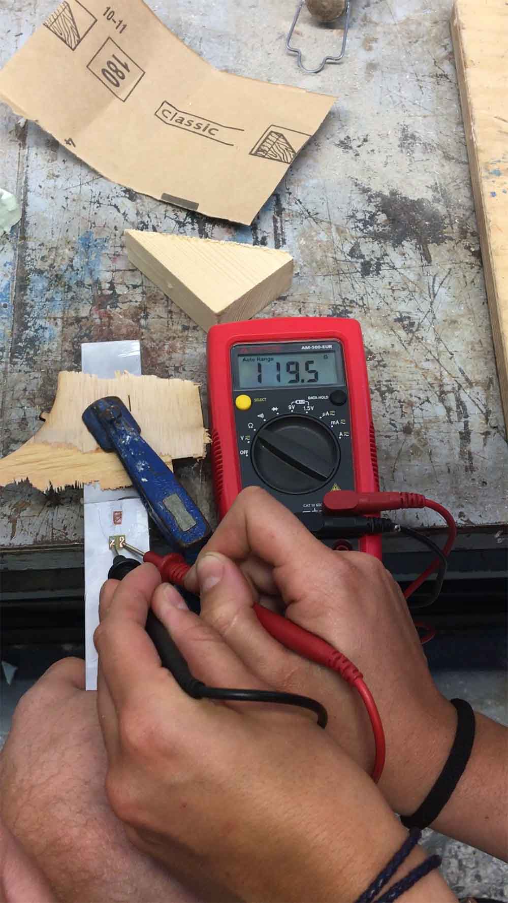
Once the code is loaded on the arduino, or any other board, you will need a known weight. Then run de serial monitor from Arduino Iddle and follow the instructions. First have the pedal with no weight, and leter hang a known weight on the position that the foot will press the most. Once that is done by increassing and decreassing the calibration number by presing a,s,d,f to increase calibration factor by 10,100,1000,10000 respectively and pressing z,x,c,v to decrease calibration factor by 10,100,1000,10000 respectively. Once you have figured the calibration number out, you can run the other sketch, the one that will calculate power. I based my code on the other code from the HX711 that was to calculate weight. Mine transform weight to force, force to torque and adds the angular velocity from the hall effect sensor.
/*
 * circuits4you.com
 * 2016 November 25
 * Load Cell HX711 Module Interface with Arduino to measure weight in Kgs
 Arduino
 pin
 2 -> HX711 CLK
 3 -> DOUT
 5V -> VCC
 GND -> GND

 Most any pin on the Arduino Uno will be compatible with DOUT/CLK.
 The HX711 board can be powered from 2.7V to 5V so the Arduino 5V power should be fine.
*/
#include
SoftwareSerial BSerial(26, 27); // RX | TX
#include "HX711.h"  //You must have this library in your arduino library folder

#define DOUT  3
#define CLK  2
float weight;
float force;
float torque;
float sp=0;
float power;

const float crank_size = 0.170 ; // Dimension of the crank in meters
int Actualstate1=0;
int Actualstate2=0;
int lastState=0;
int counter=0;
const float pi=3.1416;
int timer1=0;
int timer2=0;
int timer3=0;
float timer4=0;


HX711 scale(DOUT, CLK);

//Change this calibration factor as per your load cell once it is found you many need to vary it in thousands
float calibration_factor = 10090; //-106600 worked for my 40Kg max scale setup

//=============================================================================================
//                         SETUP
//=============================================================================================
void setup() {
  Serial.begin(9600);
  Serial.println("Press T to tare");
  scale.set_scale(10090);  //Calibration Factor obtained from first sketch
  scale.tare();             //Reset the scale to 0
}

//=============================================================================================
//                         ANGULAR VELOCITY
//=============================================================================================

void angular_velocity() {
              Actualstate1=digitalRead(3);
        delay(10);
        Actualstate2=digitalRead(3);

        if (Actualstate1 == Actualstate2) {   //If states are not the same the sketch does nothing
                    if (Actualstate1 == HIGH) {
                        counter = counter + 1;
                        // Serial.print ("Laps ");
                        //Serial.println(counter);
                       if(counter%2 == 0){
                            timer1=millis();
                       }else{
                           timer2=millis();
                                   }
                        timer3=abs(timer1-timer2);
                        timer4=(timer3/1000.0); //transform miliseconds into seconds
                        sp=((2*pi)/timer4);// radianes per second

                    }
        }
}

//=============================================================================================
//                         LOOP
//=============================================================================================

void loop() {
 /* Serial.print("Weight: ");
  Serial.print(scale.get_units(), 2);  //Up to 3 decimal points
  Serial.println(" kg"); //Change this to kg and re-adjust the calibration factor if you follow lbs

  if(Serial.available())
  {
    char temp = Serial.read();
    if(temp == 't' || temp == 'T')
      scale.tare();  //Reset the scale to zero
  }*/
  angular_velocity; //Start the function that calculates angular velocity

  weight = (scale.get_units()); //(Kg)
  force = weight*9.8;//(N) change weight to force by dividing through gravity value
  torque = force*crank_size; // (N*m) calculates torque out of the force value from the gauges and the crank dimension
  power = torque*sp; // (Watts)

  Serial.print("Power : ");
  Serial.print(power);  //Up to 3 decimal points
  Serial.print("Watts"); //Change this to kg and re-adjust the calibration factor if you follow lbs

  delay(5000);
  /*  if(Serial.available())
  {
    char temp = Serial.read();
    if(temp == 't' || temp == 'T')
      scale.tare();  //Reset the scale to zero
  }*/
}
//=============================================================================================
The last code I used is the one for the display element. It is made for an ATtiny 85.
#include
SoftwareSerial BTSerial(4, 3); // RX | TX
#include "SSD1306_minimal.h"
#include

#define DEG "\xa7" "C"

#include

SSD1306_Mini oled;

String b;
/*void splash(){

  oled.startScreen();
  oled.clear();

  delay(5000);

  oled.clear();
  oled.cursorTo(26,1);
  oled.printString( "FAB Power ");

  oled.cursorTo(25,3);
  oled.printString( "Open Source");


  oled.cursorTo(10,5);
  oled.printString( "Bike powermeter");


}*/


void prepareDisplay(){

  unsigned int i,k;
  unsigned char ch[5];
  String bluetooth;
  oled.clear();
  oled.startScreen();


  oled.cursorTo(0,0);
  oled.printString( "FABpower");
  oled.cursorTo(0,1);
  oled.printString( "BikePowermeter");

}


void setup(){
  BTSerial.begin(4800);
  pinMode(9, OUTPUT);  // this pin will pull the HC-05 pin 34 (key pin) HIGH to switch module to AT mode
  digitalWrite(9, HIGH);

  pinMode(3, INPUT);

  oled.init(0x3c);
  oled.clear();

  delay(1000);

  //splash();

  delay(8000);

 prepareDisplay();

}


void loop(){
static long startTime=0;
long currentTime;
const char * databluetooth;
//char buf;
 if (BTSerial.available()) //checks for incoming data
         {
        /* oled.clear();
           oled.cursorTo(0,0);
            oled.printString( "FABpower");
             oled.cursorTo(0,1);
               oled.printString( "BikePowermeter");*/
         b = BTSerial.readString();//reads data from bluetooth serial


        /* int str_len = b.length() + 1;
         b.toCharArray(databluetooth, str_len);*/
       // BTSerial.print(databluetooth);
           databluetooth = b.c_str();


          // printf(buf,"%s\n", databluetooth);
            //printf("%s\n",info);
              // set cursor
             oled.cursorTo(10, 4);

              // print to display
             // oled.printString("test");
             oled.printString( databluetooth );
                               //oled.printString("test2");


 }
 }
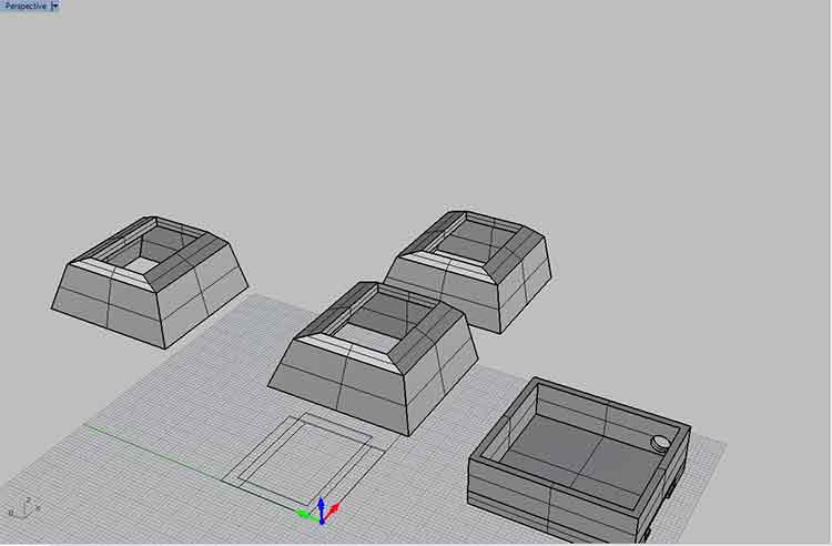
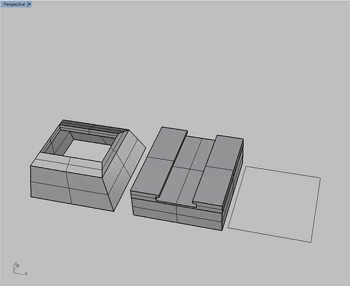
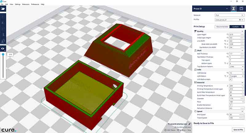
_3D MODELLING: RHINOCEROS
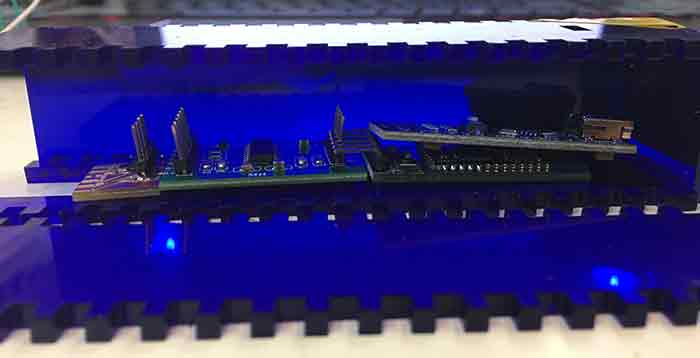
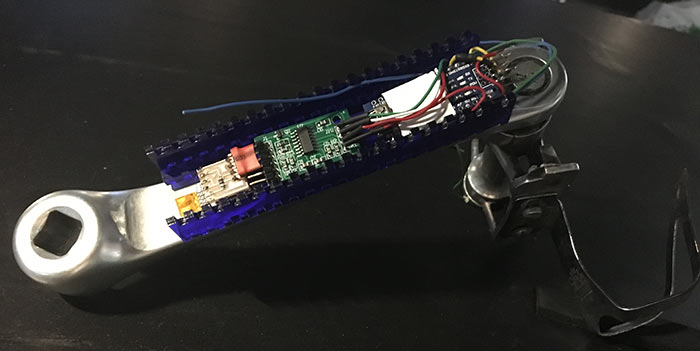
Once I had my ATtiny 85 + Oled Screen Module + bluetooth module done I meassured it with the caliper as good as I could and did a 3d model based on it. After that I did the cura for the prusa i3 and printed. Obviously it didn't fit perfectly. Even though it wasn't as bad as I had espected. From that I fixed the dimensions and did it again. This time on the ultimaker. To be honest I coudn't get the whole thing to assemble perfectly. Need to work on the clipping mechanism, and I had to detach the bluetooth module from the female headers and join it with cables for it to fit inside the case. The other problem I got with the case was the battery. I ended up powering it with a 7.4 lipo battery, and those are huge, so the was no way it couls fit inside the case. The problem was that I wanted it to be powered with a button batery but the amperage needed for the bluetooth module is just huge...
_3D MODELLING: RHINOCEROS
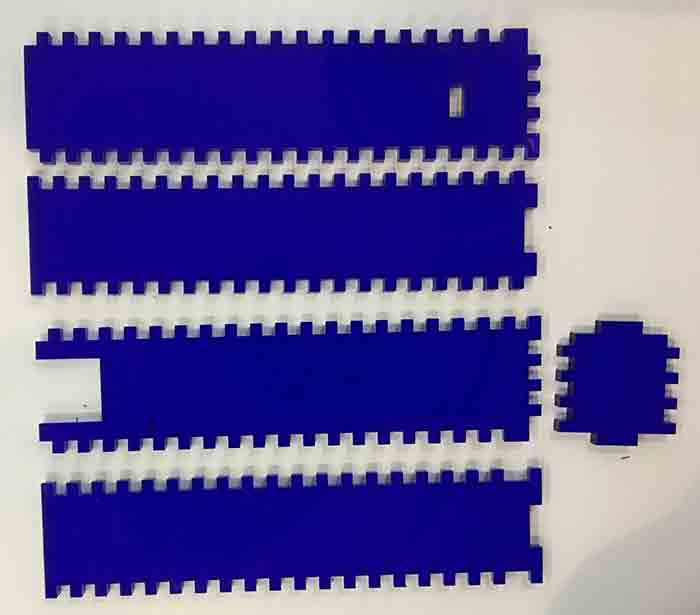
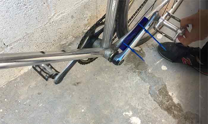
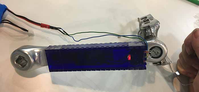
For the case of the crank I ended up laser cutting an acrylic box. It is a prototype solution. I am sure there is a need for a casing as it is a very delicate set of electronics and I also know that the solution is a moulded and casted case. Both for water and bumps proofing as for perfect fitting and space solution. The ideal process would be to scan the crank and made a custom case. Unfortunately I run out of time dealing with the coding so I had to do a meantime solution for the casing. I opted for the laser cut case. I also think is cool to have a semitransparent acrilic. It answers to the idea of open source electronics device, running out from the idea of 'black box' I measure the space between the crank and the frame with a caliper and modelled a case acording to those measures. Again, I had to redesign it and repeat it. My first one was to big, it didn't fit. The second one did fit, so I was very happy. The problem is I did this try on a bike that was not mine. When I glued it my bike's crank I realised something aweful, my crank din't have a planar back. I did all my designs thinking it was going to be planar and it wasn't. SO for the gauge gluing I had to sand the aluminium with the grinder to have a plane surface to glue them to. The conclusion is I could never put it back on the bike, even I got measured power measures and was able to send them to the screen.
All documentation and work listed here is lisenced under a Creative Commons Attribution-NonCommercial 4.0 International License.
The assembling part was kind of tricky, fitting everything on the crank was not easy, mostly because it had to fit not only on length but also in depth. It was that tricky that I failed to get the rigth dimension to put back together the crank to the bike frame. I am very sure that designing a all in one board that contains the wheatstone bridge pads, the amplifier chip, the microprocessor and (maybe) the bluetooth will make an easier to fit device.
BACK HOME <<<