Weekly assignment: design, make, and document a parametric press-fit construction kit.
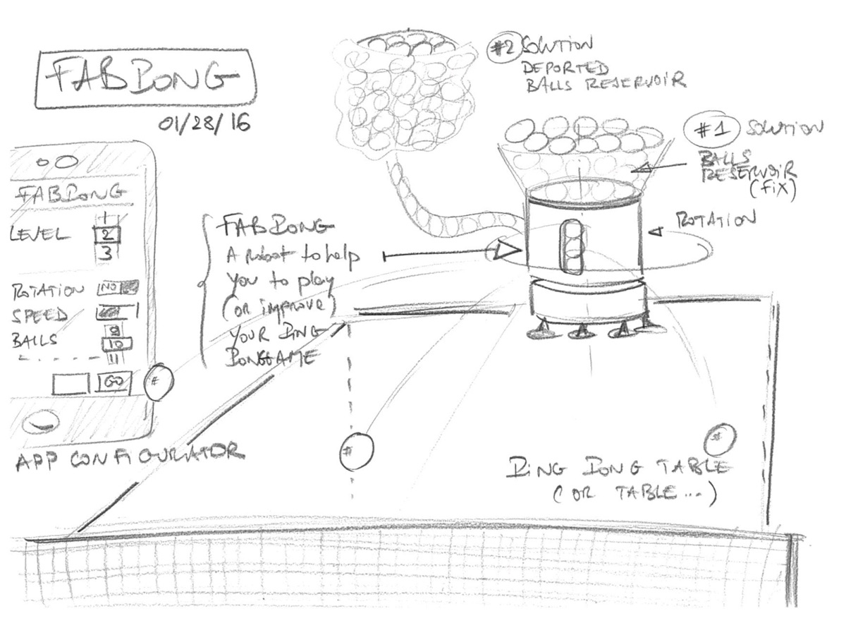
Making a press-fit construction to build... a regular dodecahedron!
Maybe you don't know what a dodecahedron is :-)
A polyhedron is a mathematical solid made with different faces. A box is a polyhedron with six faces, called a tetrahedron.
A cube is a regular tetrahedron, because all of the faces are the same.
So, a regular dodecahedron is a 12 faces polyhedron, and all the faces are uniform.
And the last but not least, each face is a pentagon, which is a 5 sides polygon and one of the most interesting polygons....
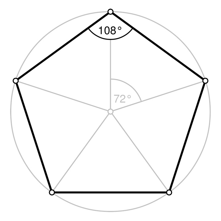
A pentagon
A regular dodecahedron: 12 pentagons, 30 edges
Why pentagons are so interesting?
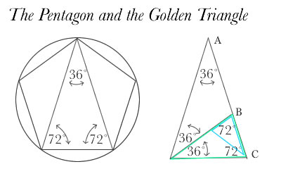
I like pentagons for many reasons but the most important of them is that pentagons contains "Golden Triangles".
That means pentagons contains an ideal proportion, called "Divine Proportion".
Euclid defines the "Divine Proportion," as the following relationship: when a line is divided such that the smaller section of the line (BC) is related to the larger section of the line (AC) in the same ratio as the larger section is related to the whole line (AC), then the line is divided in the "Divine Proportion".
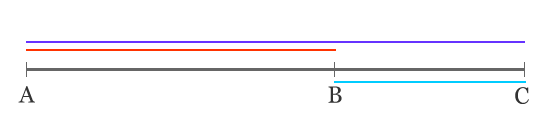
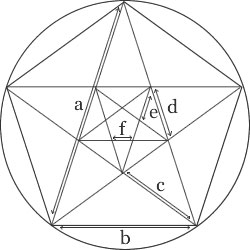
Divine proportion is the ratio a to b which is equal to b to c, c to d etc...
How to make a press-fit contruction kit for a regular dodecahedron?
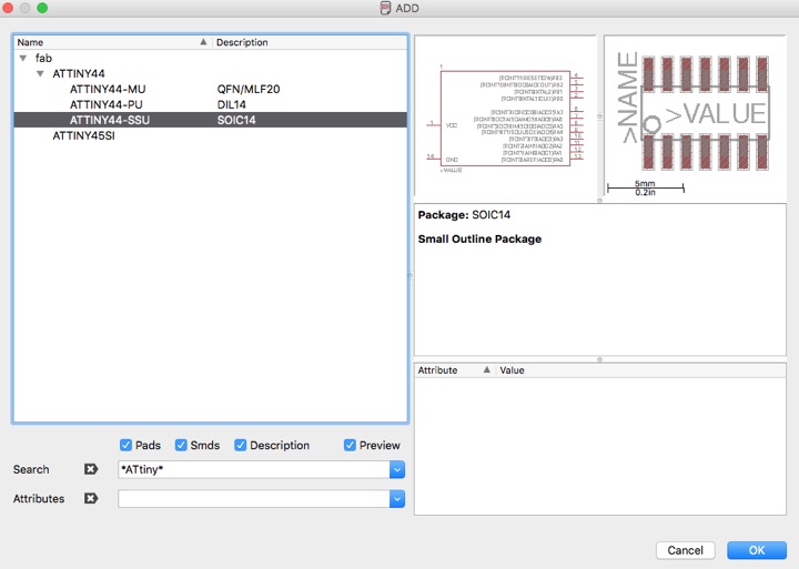
1) choosing a parametric software
The first step is to modelize (on 2D) the shape of the dodecahedron for the wood or cartoon board which will be cut by the laser machine.
I feel easy with Blender, the 3D and rendering software I've used for modeling my project last week.
I've tested FreeCAD too - a free parametric 2D/3D software based on constraints between each parts (lines, circles, ...) of a shape - that I liked much.
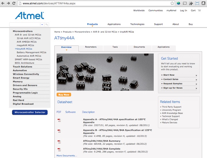
Then, there's Rhino I've discovered a few weeks and that includes some essential parametric features to design the needed geometrical shape for the dodecahedron.
Two ways can be envisaged to use parametric features with Rhino:
. using Grasshoper module which allows function and process between each parts of a shape - each part has inputs and outputs - so you can modelize and adjust sizes in seconds thanks to cascading effects, because all the pieces of the scheme are linked by mathematical functions.
. using "blocks". When the same piece of shape is used many times, it can be built serately and then included in the final scheme as a "block". A modification on the block (in the separate file) will affect all the blocks in the final scheme.
So I've decided to use "Blocks" method because a/ it's the easiest way to use parametric features with Rhino b/ I needed to learn/improve my experience with the very essential, popupar Rhino and c/ a first step to Grasshoper.
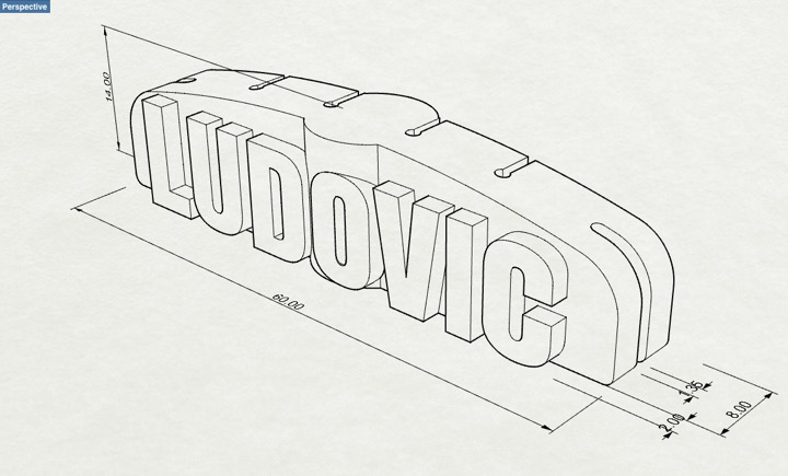
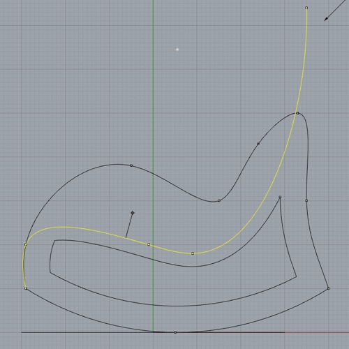
2) designing the initial shape
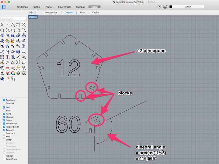
The initial shape of the dodecahedron must contain:
. 12 similar pentagonal faces
. 60 elements to link faces (I chose to use 2 elements to link 2 faces), with the right dihedral angle (116,565°).
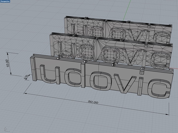
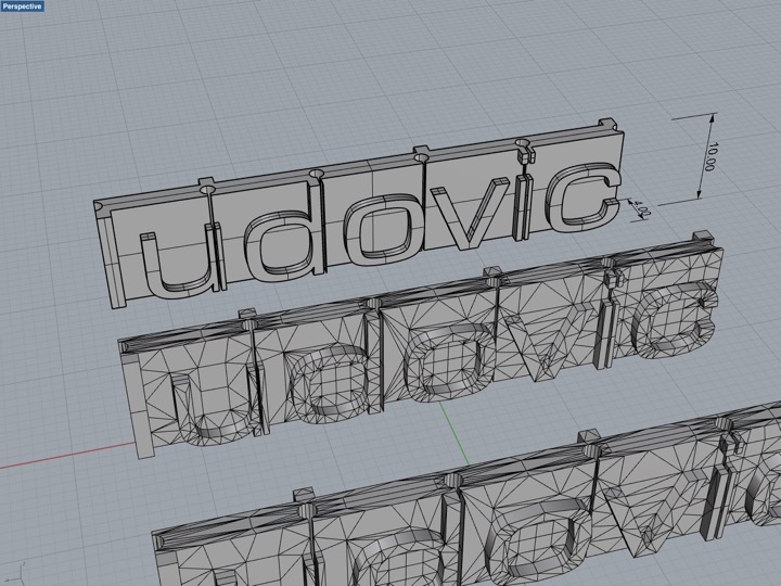
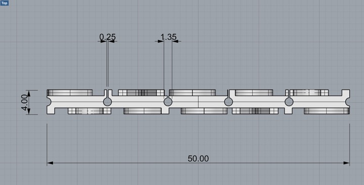
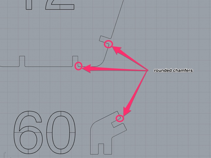
To link faces thanks to the elements, we need to envisage some nicks on faces and elements:
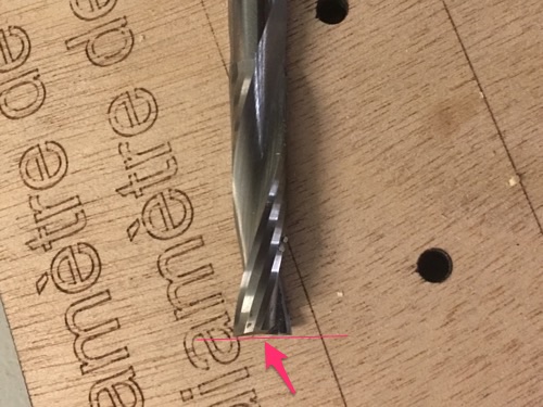
. each nick must have a 5mm width, like the thickness of the cartoon board;
. each nick must be assemblied easily: please note that chamfers are essential.
By using "blocks" to design these nicks, it's easy as 123 to adjust or modify in seconds 120 nicks in the global shape!.
Result
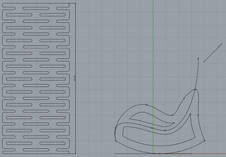
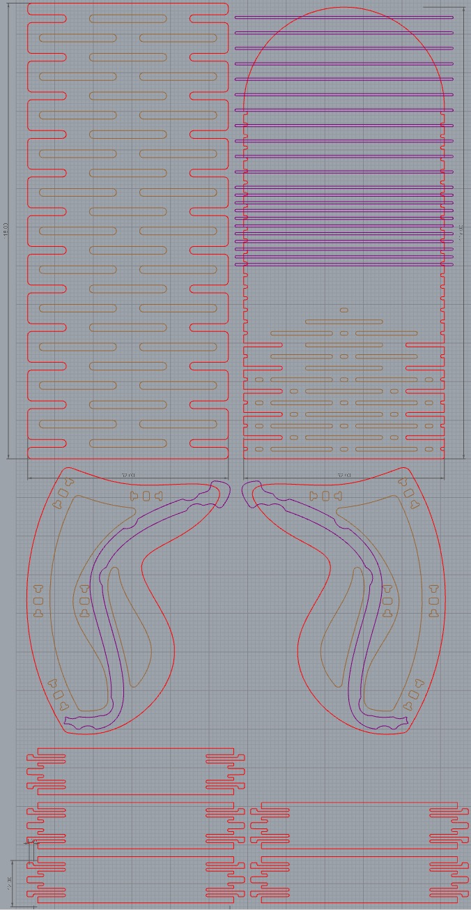
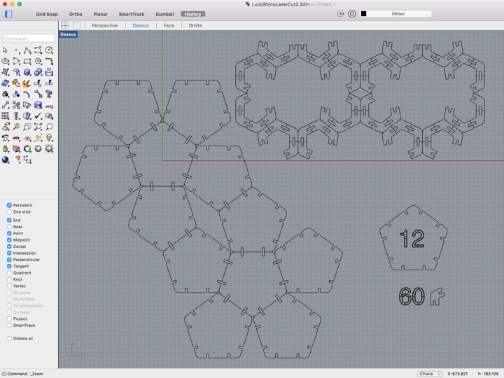
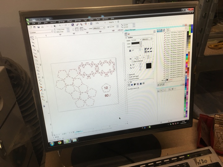
3) replicating the initial shape, designing the file for the cuting
It's important to:
. design all the shape into a 1000mmx70mm area, cuting-area size of the laser machine;
. minimize the area to save raw material.
Result
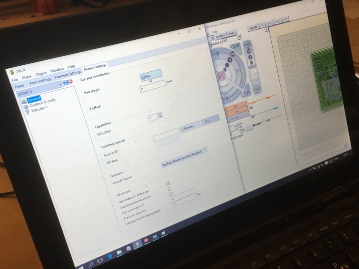
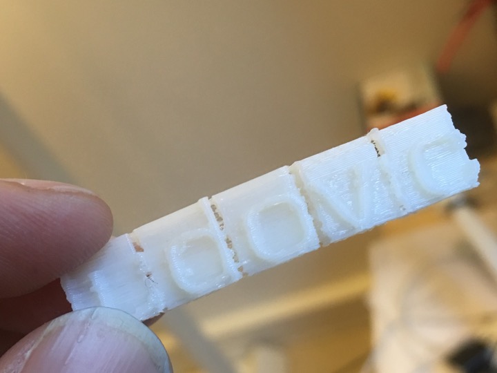
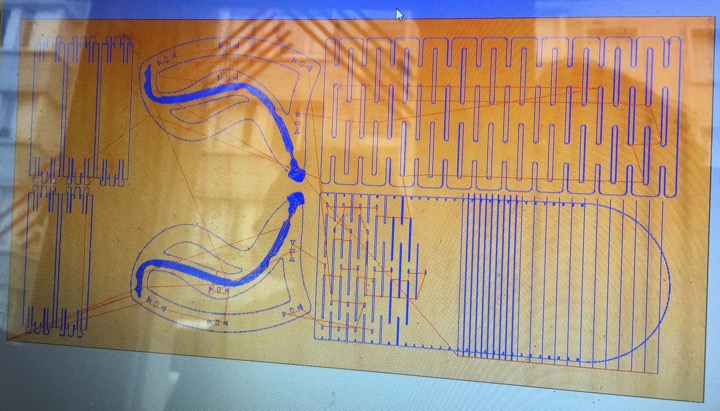
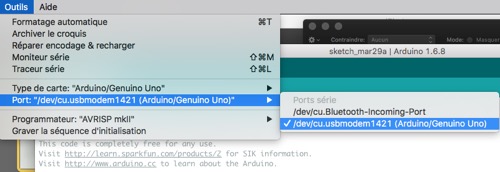
4) customize our file to initialize the cuting or the engraving by the laser machine
The different lines of the shape must be translated and understood by the laser machine software like:
- something to be cut -> strength of the laser is nearly max;
- something to be engraved (written) -> strength of the laser is light.
- something to be filled -> strength of the laser is light with many close moves
Other parameters have been taken in consideration: speed cuting, turn speed, ... depending on which material is used and which effect we want (cuting, engraving, filling...).
These parameters must be provided by the FabLab and must be strictly followed... Fire risks!
Result
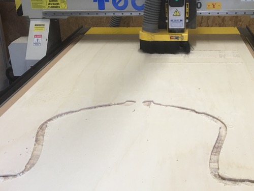
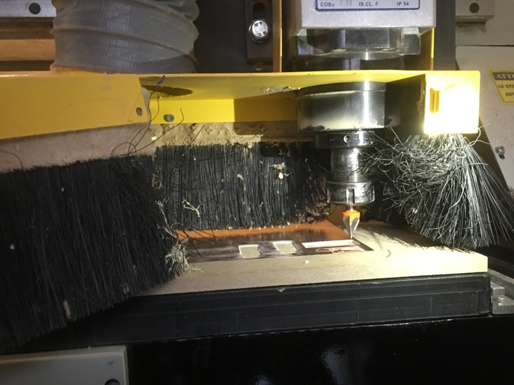
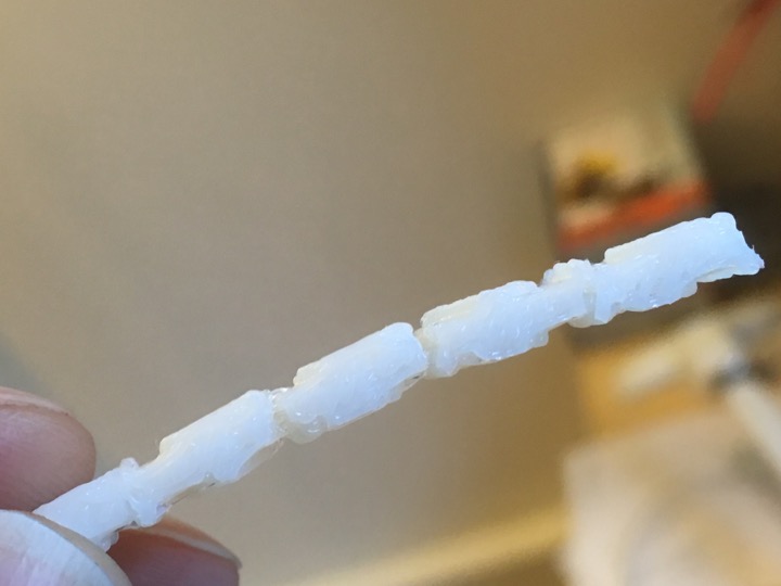
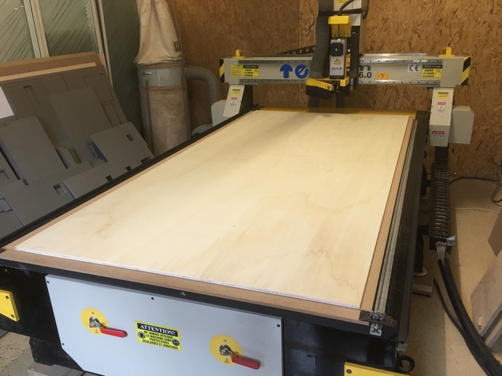
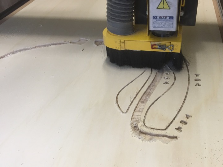
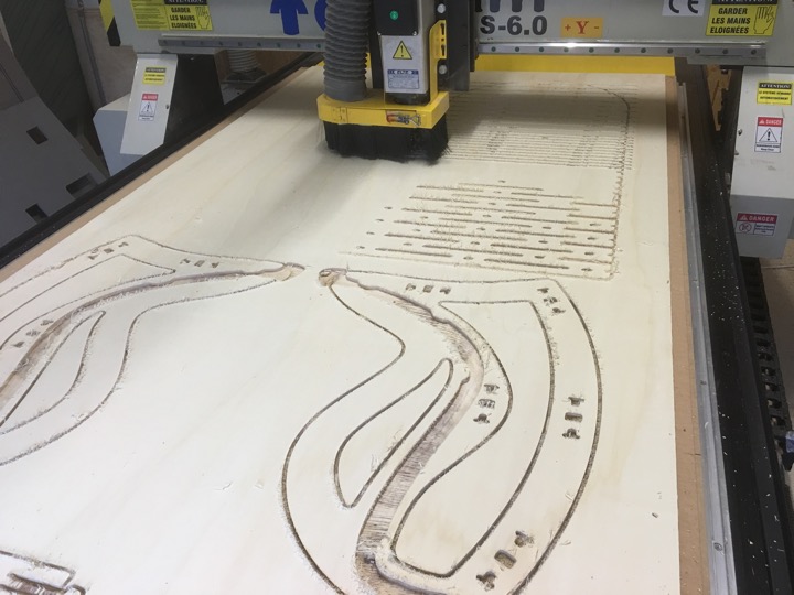
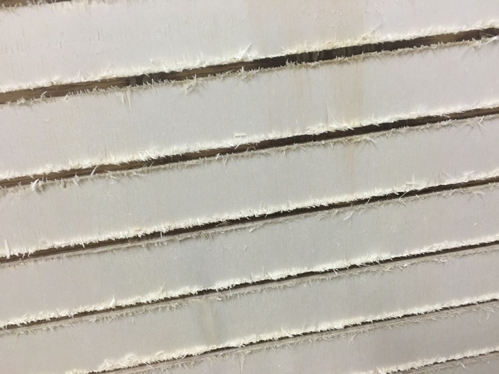
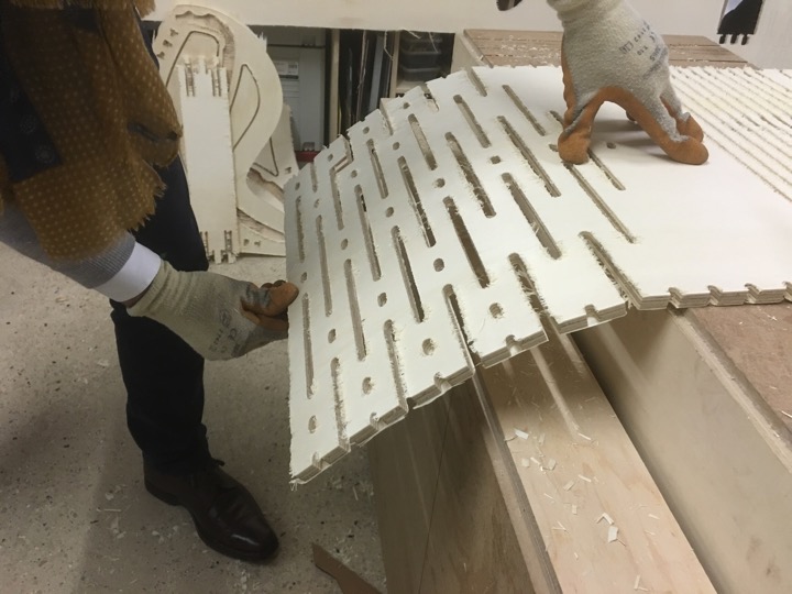
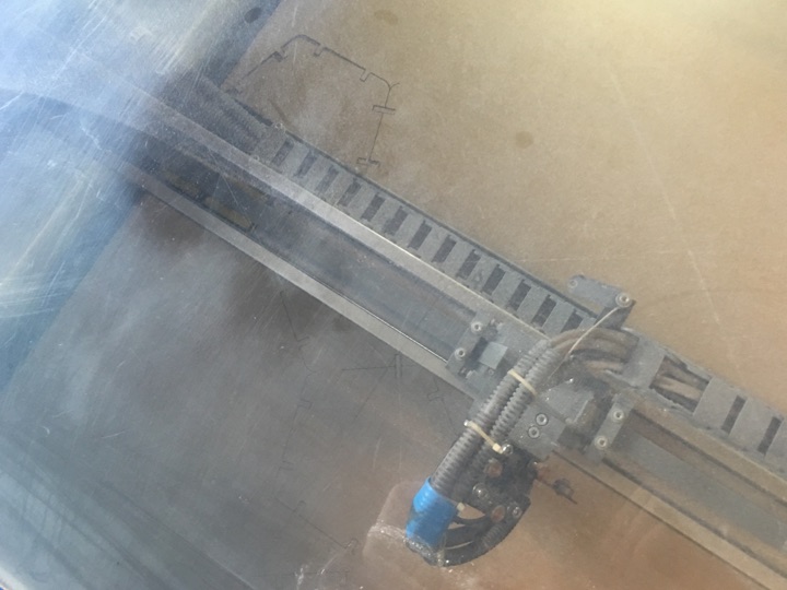
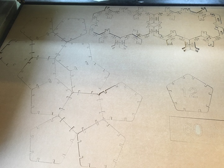
5) cuting with the laser machine
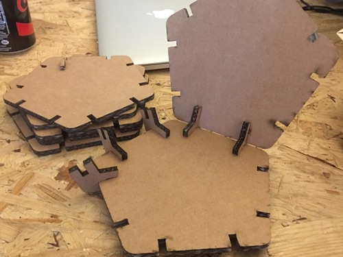
For a first try, i've used cartoon board. So the potential design errors are less expensive ;-)
Laser-cut machine in action
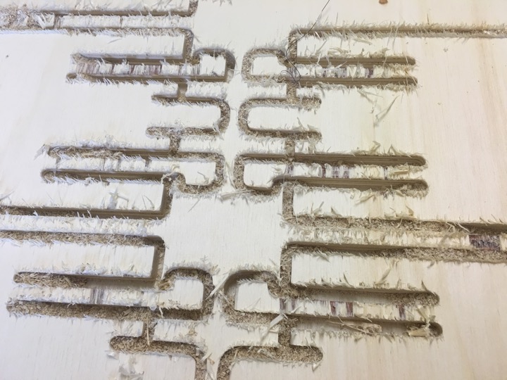
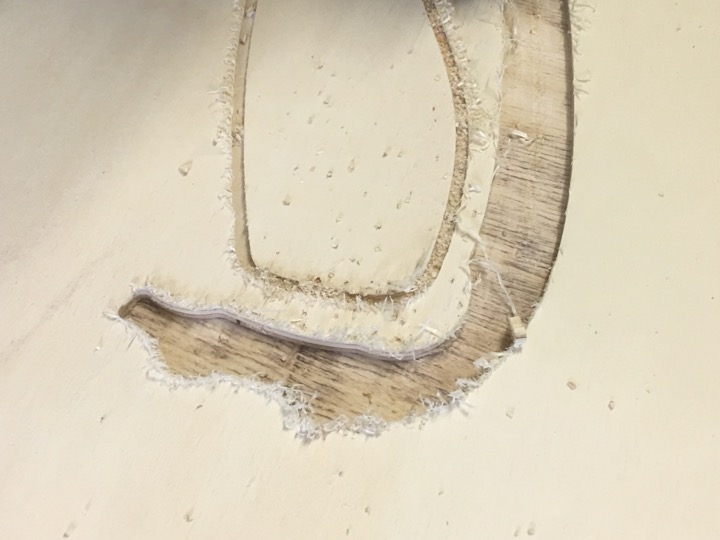
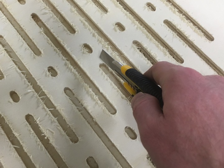
Result
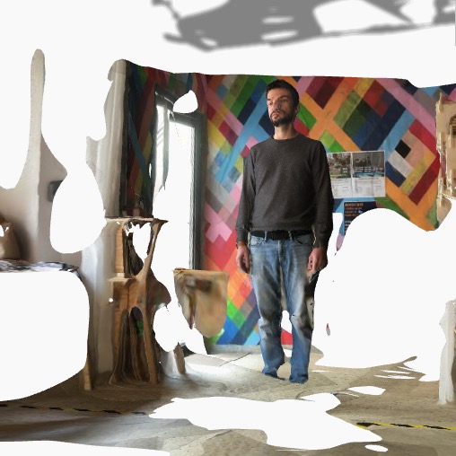
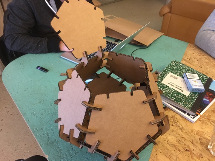
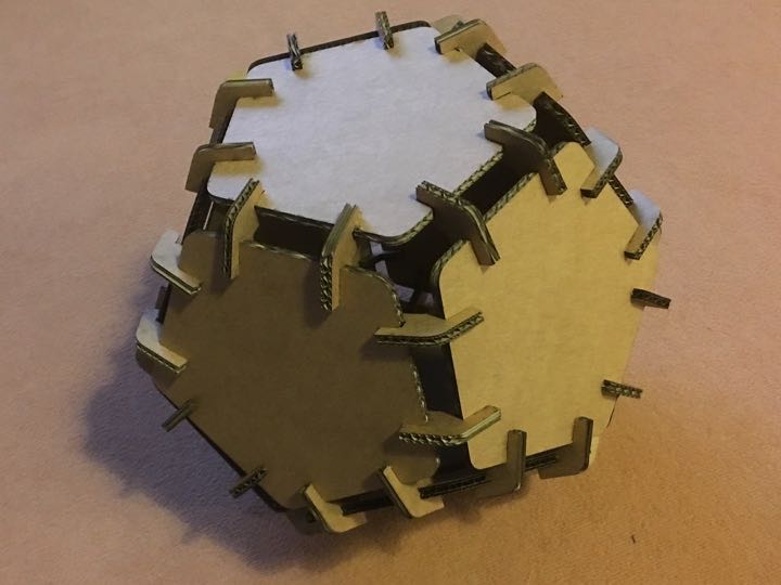
6) putting all the pieces together
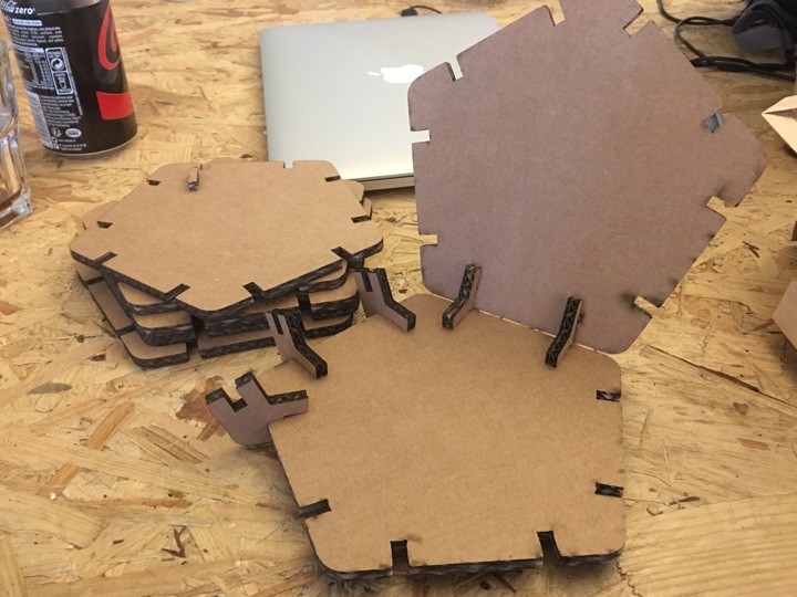
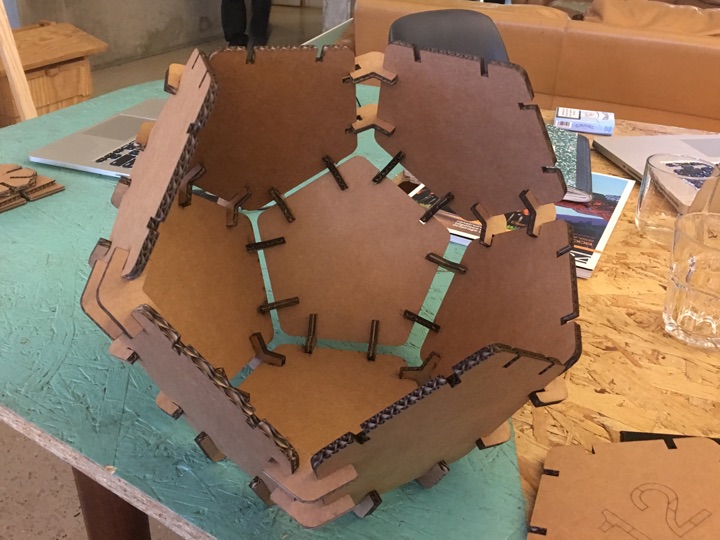
Result (cool!)
Dodecahedron from Ludovic on Vimeo.
All my files are available here;-)