MY FINAL PROJECT
A CONNECTED BIRDHOUSE
Material: - Plywood - PCB, and electronic components - input sensors Softwares: - Rhino3D, 3D design software
- Vcarve Pro, software to prepare files for CNC
- Eagle, for the PCB designing
- ArduinoIDE, for the programming
- Processing, for the programming
ABOUT MY FINAL PROJECT
INTRO
My project is a BirdHouse with several nests, and this BirdHouse is a connected object. The aim is to be able to follow the activity inside the BirdHouse with sensors. And to read this activity on a Interface.
MATERIAL
To do my final project I need following materials: - Some marine plywood for the structure - Some electronic components, * including sensors: . motion sensor for presence of birds . water level sensor for water tank . ultrasonic sensor for seeds tank) * including Wireless (Wifi, and/or Zwave)
PLANNING
Step 1 (June 2016): . build the infrastructure . build and test the electronics (at least with the motion sensors, and with wire connection - no wireless -) . build a V1 of interface Step 2 (End of 2016): . add sensors (water level sensor for water tank, ultrasonic sensor for seeds tank) . include Wireless (Wifi, and/or Zwave) . add autonomous powering system . update interface (V2)
STATUS ON TASKS
3D design for the infrastructure - 3D draft: DONE - 3D design on Rhino3D: DONE Big CNC to mill the infrastructure Milling plywood on CNC: DONE Mounting the infrastructure: DONE Protecting the infrastructure (resin, varnish): DONE PCB design, and production Design of PCB: DONE Milling of PCB: DONE Soldering: DONE Programming of microcontroller (V1) Programming: DONE Tests: DONE Validation: DONE Interface programming (V1) Programming: DONE Tests: DONE Validation: DONE Programming of microcontroller (V2) Programming: TO BE DONE Tests: TO BE DONE Validation: TO BE DONE Interface programming (V2) Programming: TO BE DONE Tests: TO BE DONE Validation: TO BE DONE
DETAILS
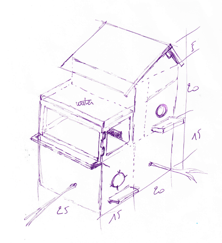
The idea
|
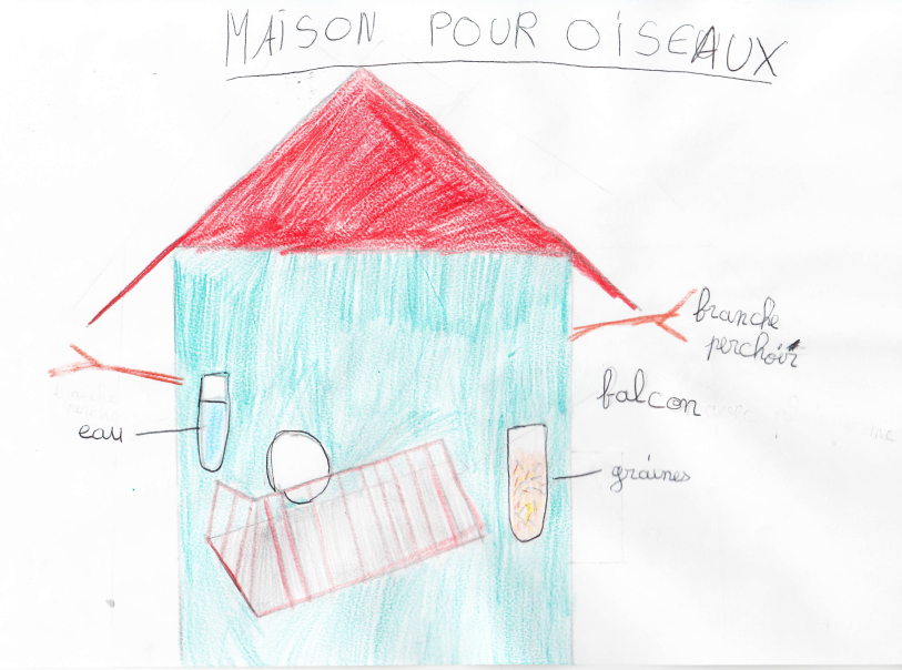
First idea from my youngest daughter
|
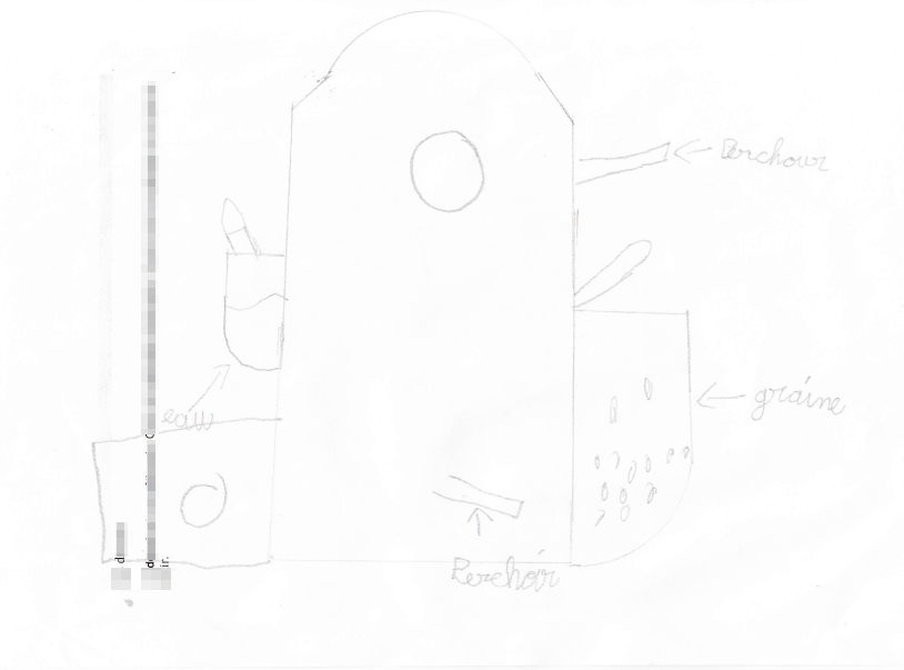
Second idea from my oldest daughter
|
|
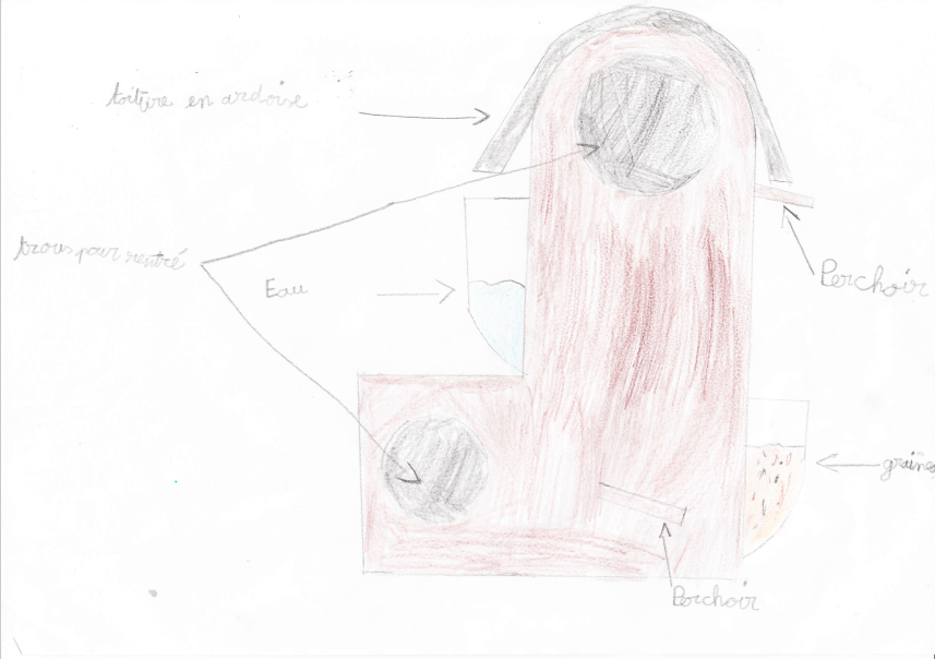
Third idea from my son
|
My compilation of the children's draws
|
|
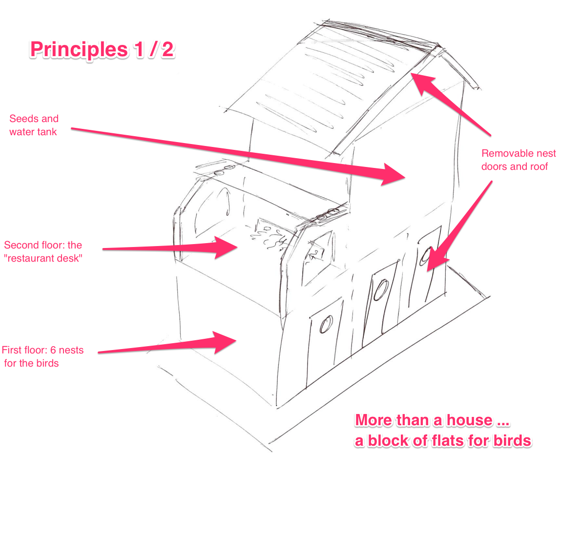
The final project - principles 1/2
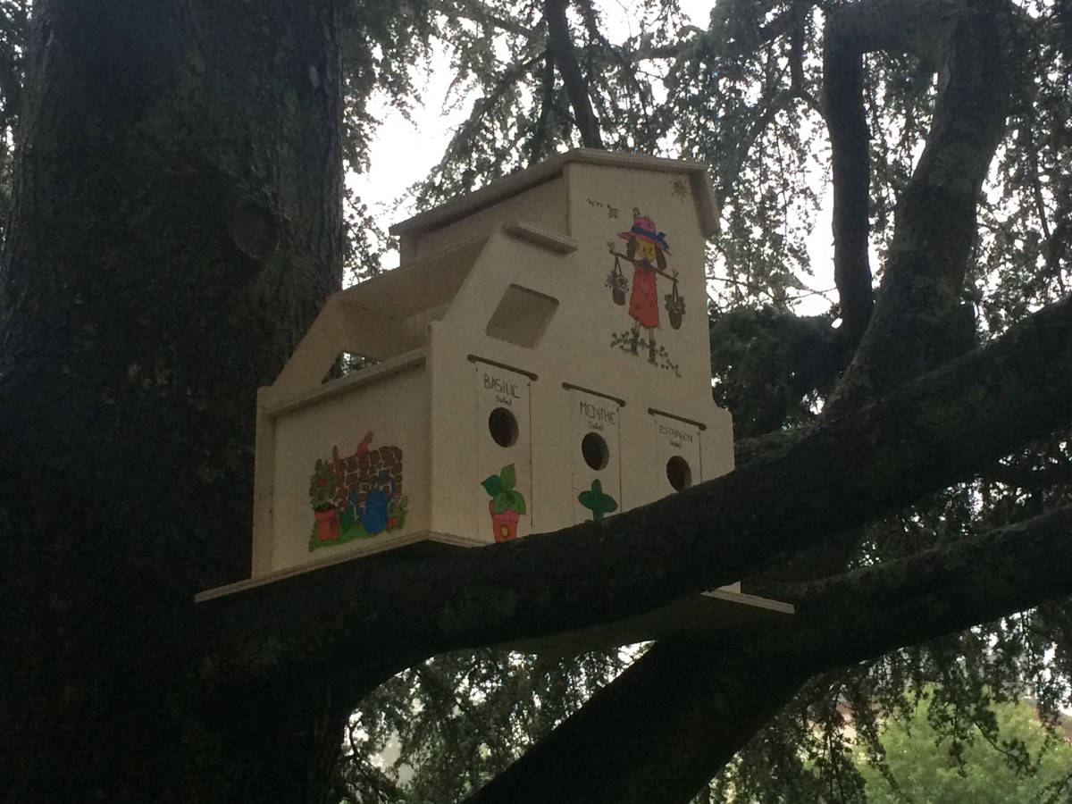
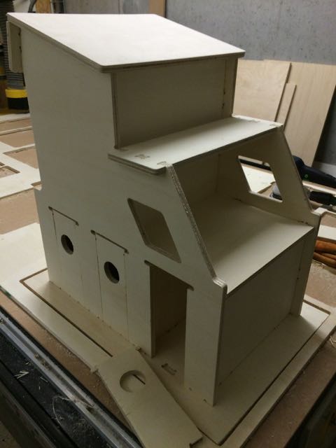
More than a simple birdhouse
A block of flats for birds
Structure 100% done in V1
|
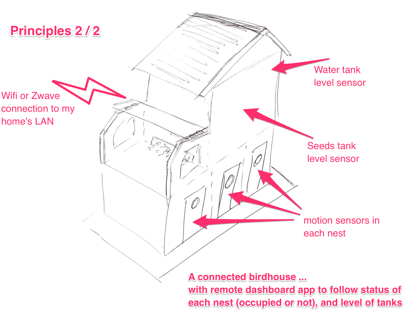
The final project - principles 2/2
A connected birdhouse
With a dashboard app (remote in V2, local in V1)
to follow activity in the nests (in V1)
And to know the level of tanks (water, feeds) (in V2)
|
Building the infrastructure
|
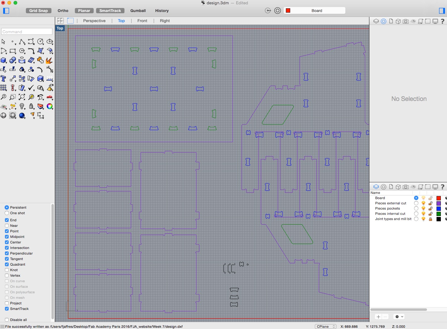
Designing the pieces in Rhino3D
All the design is done in 2D, using Rhino software
A lot of joints, so I have to take care of the joint "consistency"
Here are the rules I followed when I did my Rhino file:
- usage of layers: 1 layer in Rhino per Job with the CNC + 1 layer for the board + 1 layer for my joints models and the Mill Bit
- the mill bit I decided to use is a 6mm diameter
- the circular arcs of the mill bit on my schema are 6.05 mm (not 6.00)
|
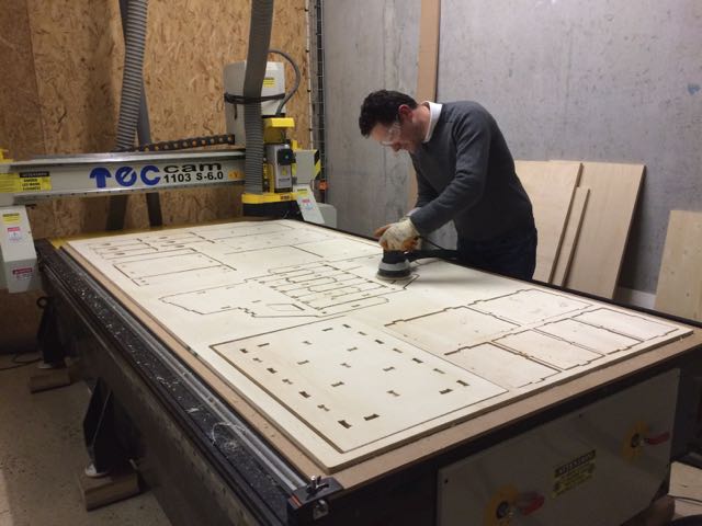
Milling with the Big CNC
A the pieces are on a single 240cm x 120cm plate
|
|
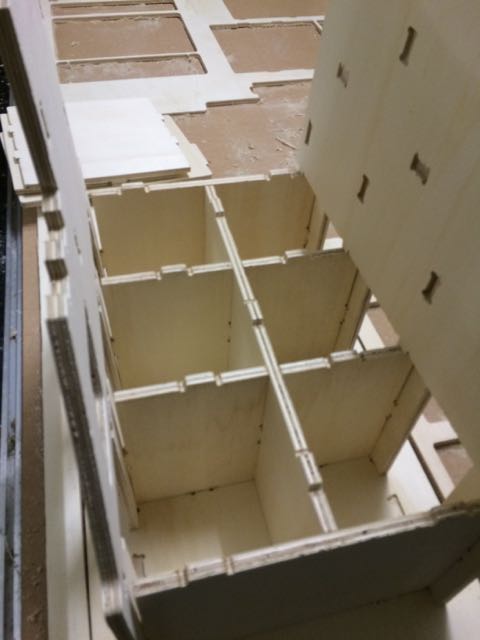
Starting the assembly
To check the joints
|
The birdhouse is mounted
All the joints were OK :-)
|
Doing the electronic
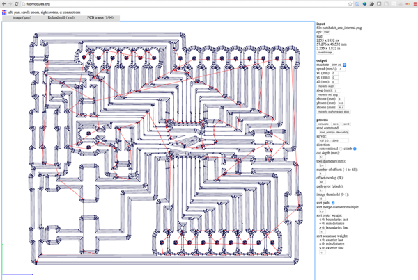
As I'm only able to program via Arduino IDE, the PCB I will use is a Satshakit. Here is the Satshakit documentation, and here is the Satshakit GitHub page.
|
Designing a Satshakit
|
Working with Fabmodule
|
|
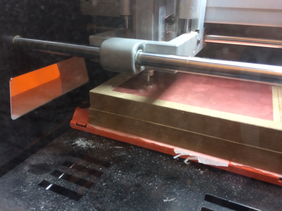
Milling with the Roland MonoFab SRM-20
|
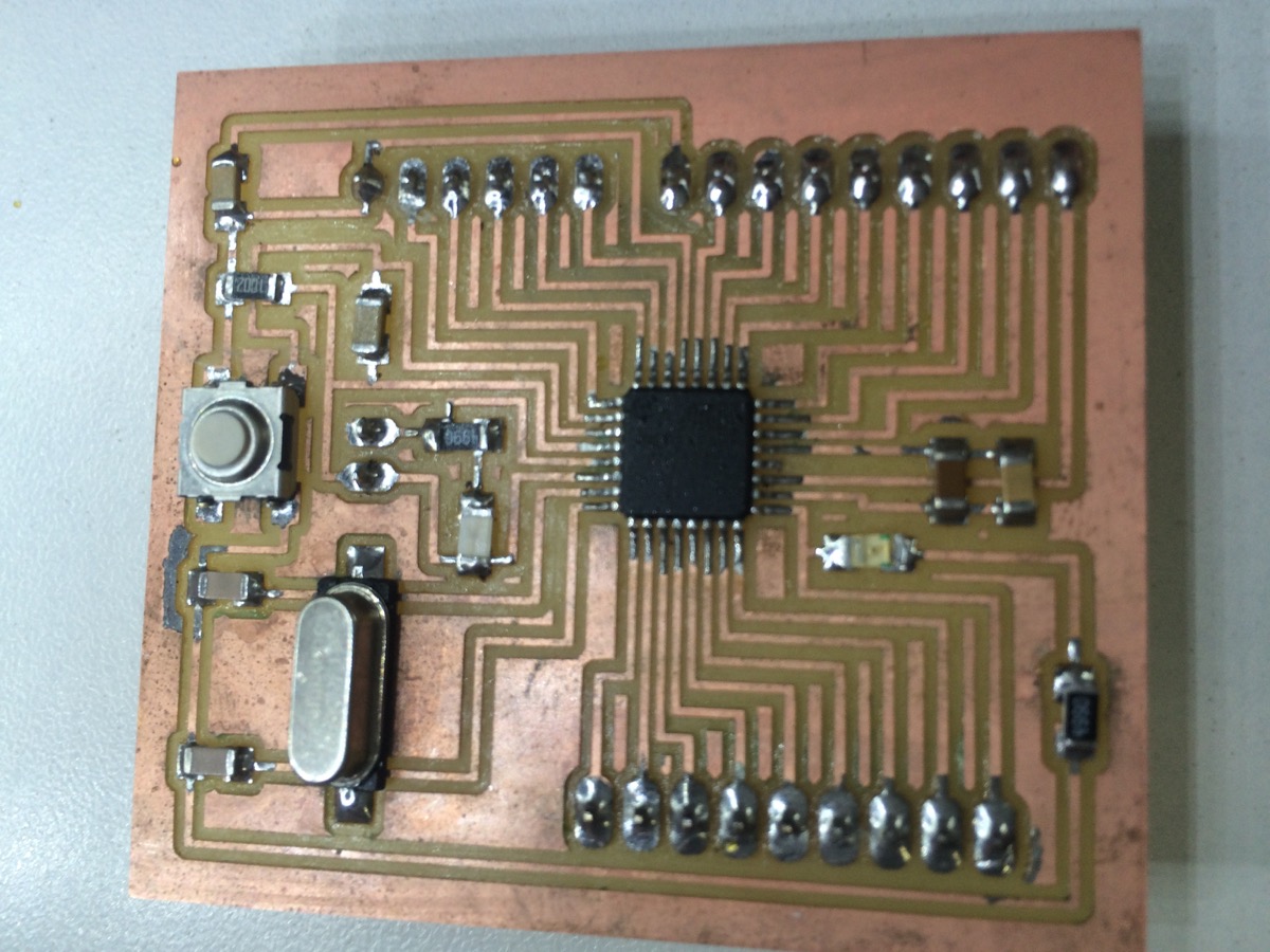
PCB Board achieved
|
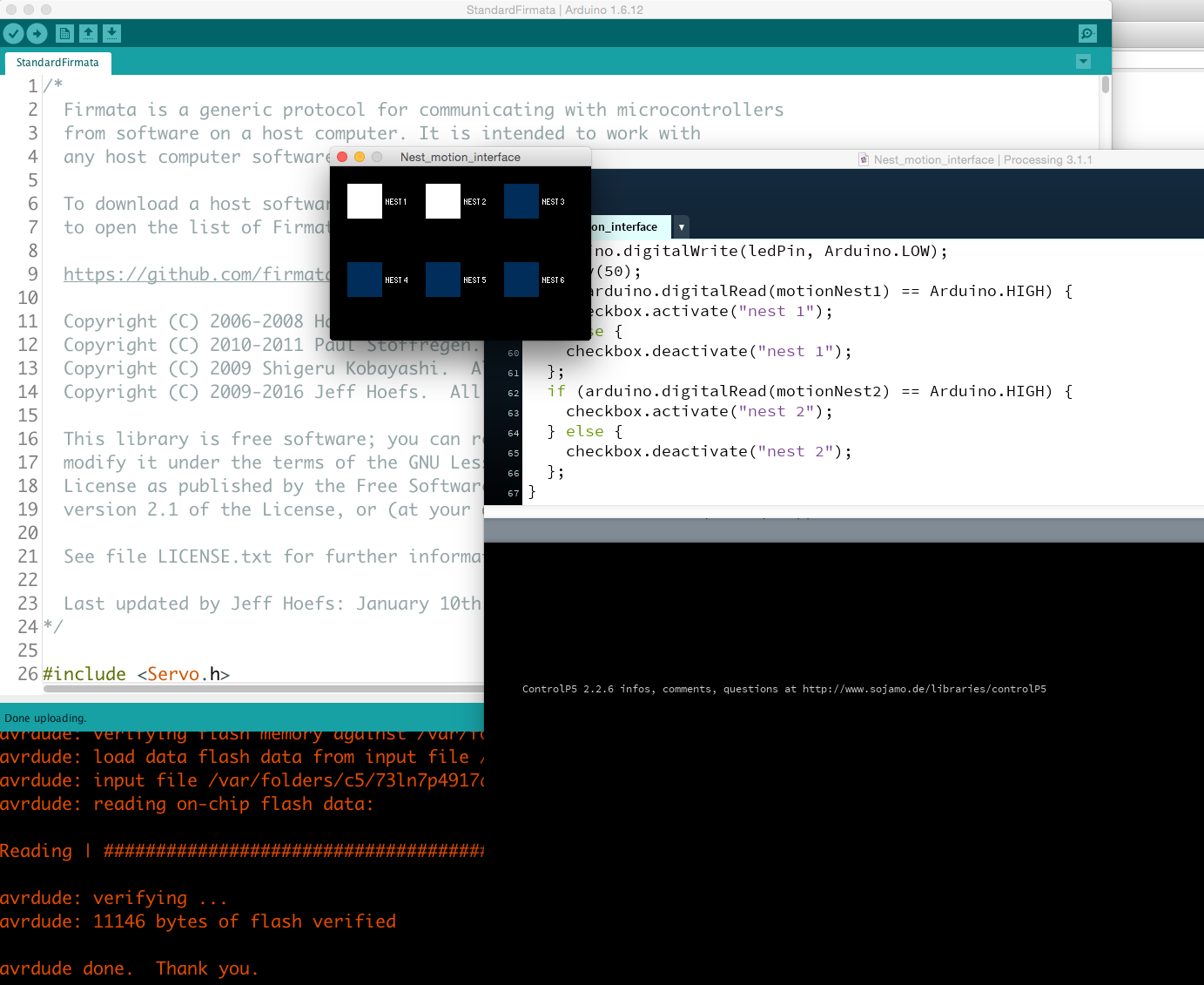
Doing the interface
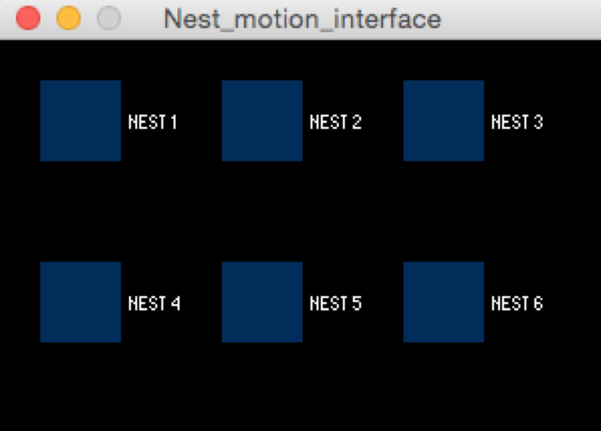
The interface is showing me if there is some motion inside the nests of my birdhouse. For this I have 1 motion sensor in each nest of my birdhouse. The display is a box showing the 6 nests of my birdhouse
|
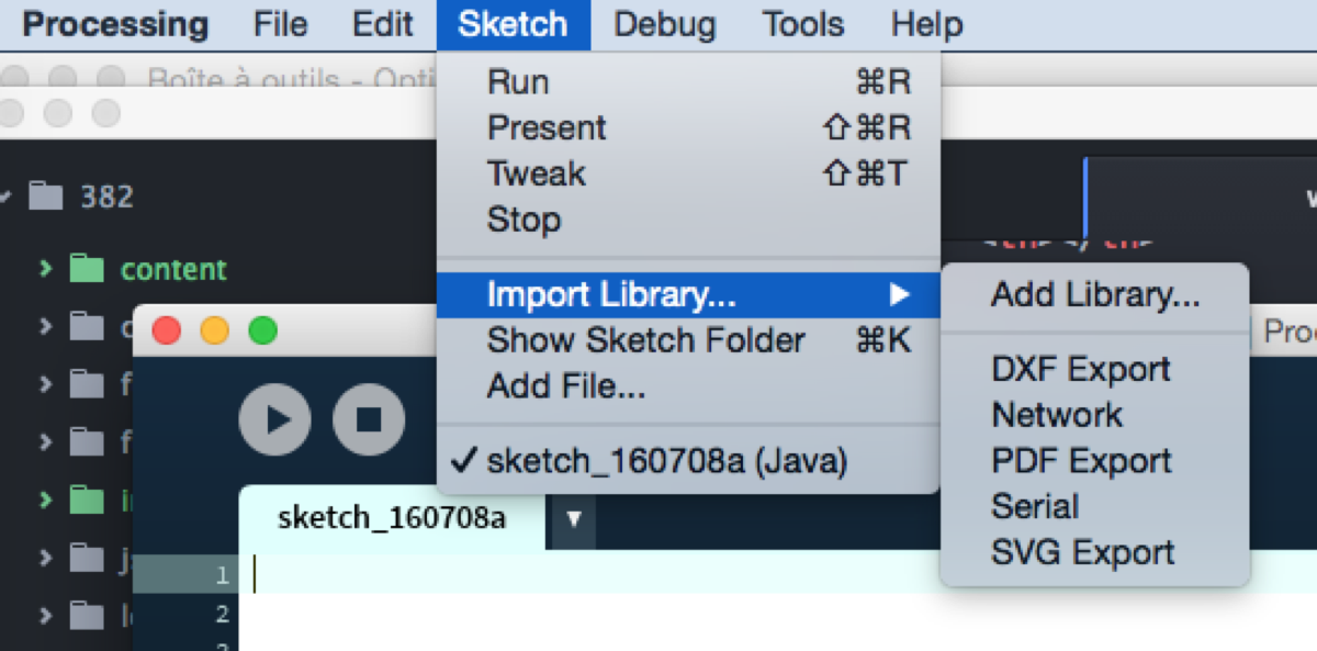
Programming interface with Processing
|
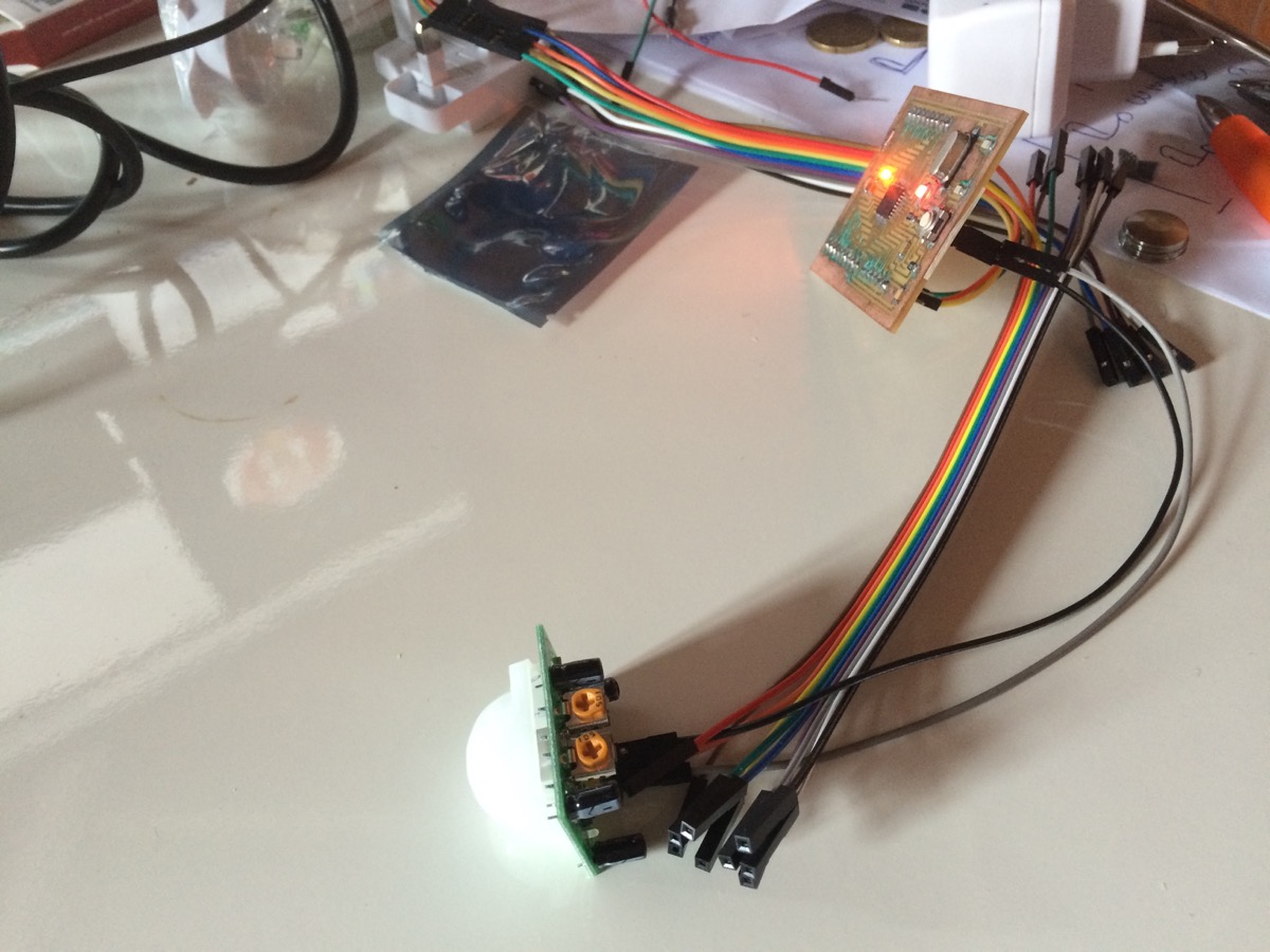
Testing Motion Sensor connected to Satshakit
|
|
My interface : no activity in my BirdHouse
|
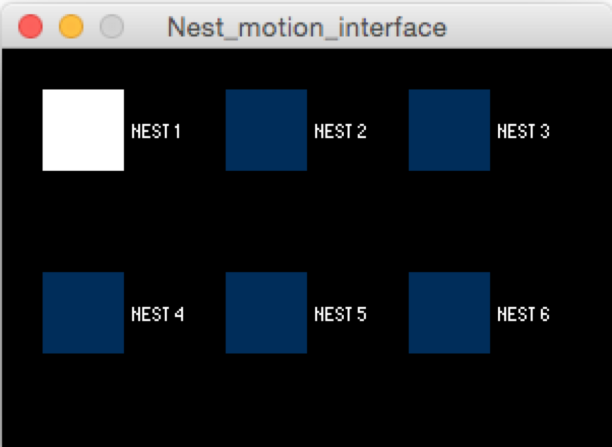
My interface : there is a bird in Nest 1 !
|
|
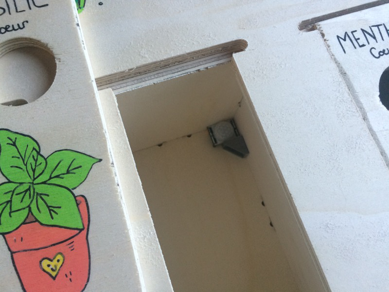
Physical integration of the motion sensor in the nest
|
With the door closed, still need some tests and tuning to find the good physical position for the sensor
|
2ND ROUND
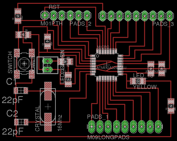
Doing a custom board
My custom Satshakit
For the 2nd round I did a custom satshakit that includes:
- a 3 pins connection (pin/gnd/vcc) for the 6 motion sensors
- a 6 PIN header for ISP to connect my FabISP to program the board, using standard cable
- a double LDO system (3.3V, and 5V)
- I keep all the other pins as it is to be able to use it as an arduino
- I added some text on it to reference GND/VCC or -/+ notably
|
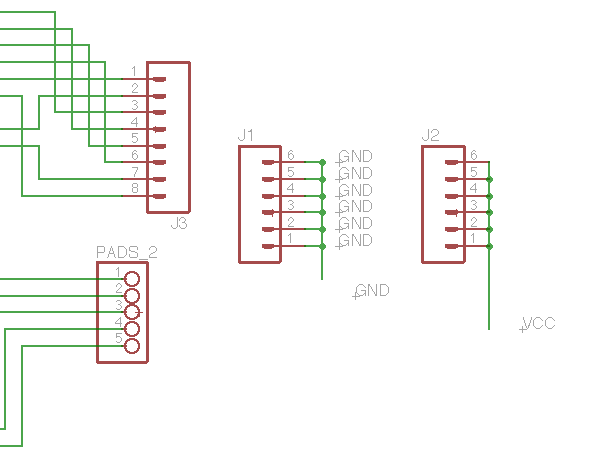
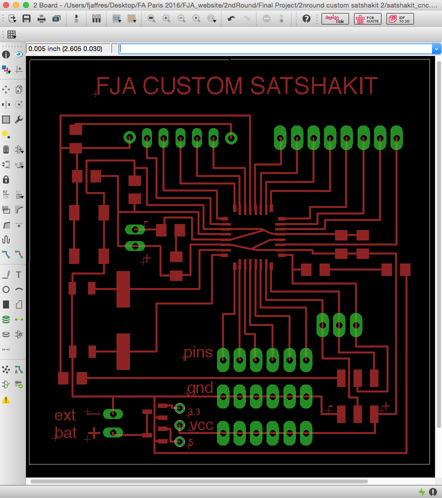
Working on Eagle: modifying all the pads, adding pads for GND/VCC for sensors
|
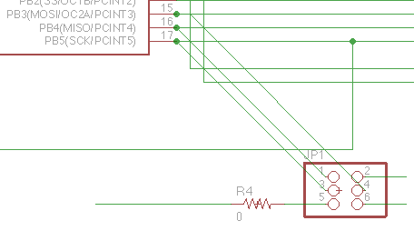
Working on adding the 6 PIN header for ISPnot easy to route the Reset, a 0 ohm resistor was necessary to pass upper the GND.
|
|
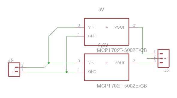
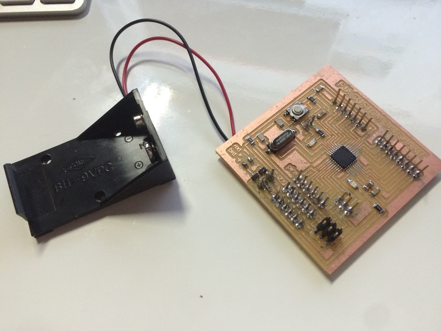
Working on adding connection for the external battery, like a 9V battery, with 2 LDO systems, 3.3V and 5V, in order to be able to select (with a simple jumper) the VCC_Out for the whole board.
The idea is notably to be able to use the card in 3.3V in case of some attached component cannot work with 5V (like ESP8266 for instance that I planned to add in the future to connect via WiFi to my house)
In eagle, I had to import a Library from a Script file (.scr) that I uploaded from Farnell website, indeed I ordered my components for this board on Farnell, and LDO was not the ones from the FabAcademy list
This specific library is also in the files in my outputs
|
Here is the board view of my Custom Card
|
|
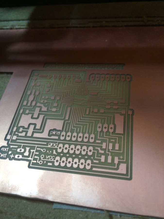
Milling the board on the Roland SRM20Result is great, except the route of the ground below LDO which was connected to VCC_In, a cutter was useful to correct the trace after production :-)
|
Now soldering the components on the PCBHere is the result
|
|
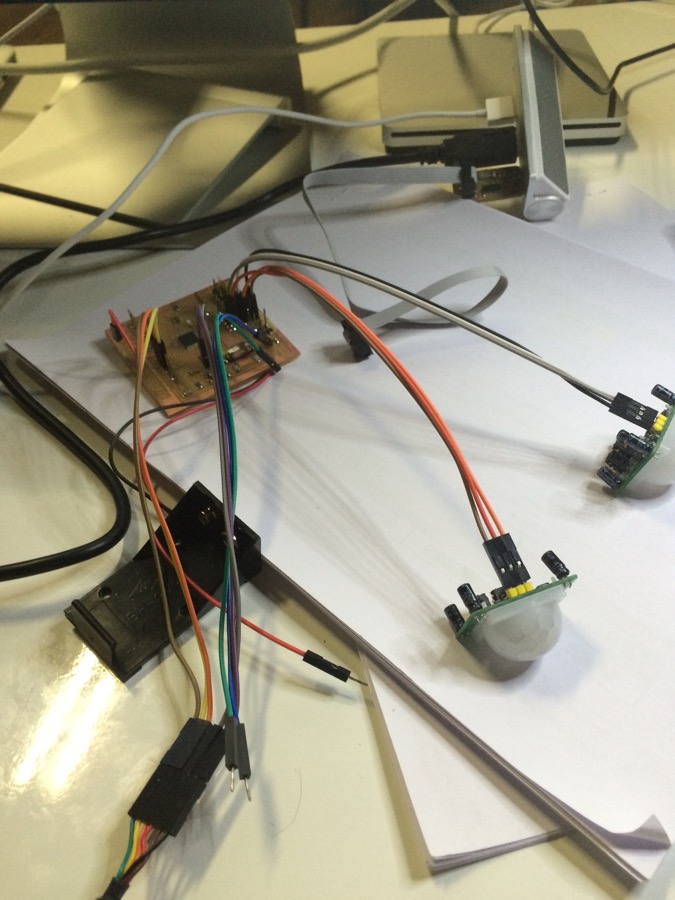
Connecting FabISP (to burn the board), FTDI (to program it and for the Processing => Firmata => Arduino flow),2 motion sensors for my tests
|
Burning card with FabISP, testing a simple Blink program on itThen pusching StandardFirmata program from Arduino IDEAnd then pushing my Processing programEverything is working!See following video...
|
Video
Burning and testing my Custom Board
Video
Running my program on my Custom Board