Designing the Hello Volt board in Eagle
0. Intro
I've never designed a circuit so I decided to keep my goal simple making the board with a button and a led. I choose to design my circuit with Eagle, because it seems one of the most popular software for this purpose and has a good freeware version. You can download it here. In Eagle the design of the circuit is made by two main file: the schematic and the board. The first one just describe the components and their connection, the second one is the actual design of your board that you will produce, with your pads for the components in position and the paths that connect them.
The main process is the following:
- Create a new project
- Insert the components in the schematic file
- Make the connections between your components
- Switch to the board file and get components in position
- Make the paths
- Hide all layers except for pads and paths
- Export your design for production
1. Create a new Project
Open Eagle, and the Control Panel will pop-up.
Right click > New > Project (you will see a new folder in the control panel)
Right click on the project folder > Open
Right click on the project folder > New > Schematic (a window will pop-up)
1.1 Add a Library
In order to use an external library of components (in my case the Fab library) you need to download the .lbr file and place it inside the "lbr" folder. In the mac you can find it in Applications > Eagle > lbr. Or you can just drag and drop the file in the control panel inside the Libraries voice.
2. Make the schematic
The schematic is just the logical diagram of your circuit. It is a representation of the elements of the circuit using abstract, graphic symbols rather than realistic pictures. A schematic omits all details about the actual position of your components, their size etc.
List of the components for the blinking led circuit:
- 1x Attiny 44A
- 1x Capacitor 1μF
- 1x Pin header 1x6
- 1x Pin header 2x3
- 1x 20 Mhz Ceramic resonator (We had a smaller one than the resonator inside the fab library so I made a custom package for this that you can download here)
- 1x LED
- 1x Button
- 2x Resistor 10kΩ
- 1x Resistor 499Ω
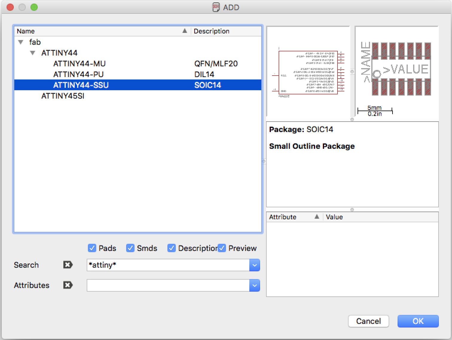
Having clear wich components we need is time to add those in the Eagle's schematic. To do this we just need to use this tool  on the left bar: a window that browse our libraries will pop-up.
The search field doesn't work very well, a trick that can help is to use asterics before and after the keywords
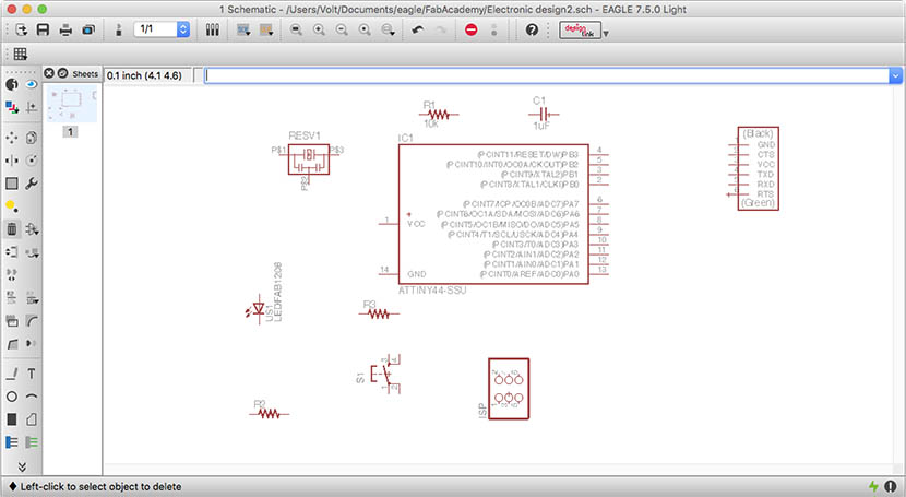
After you have placed all the components (take care that packages are of the right size for your components) you will have more or less this situation
Now it's time to make all the connections between the components, I used the Echo hello-world board as reference for my connections. For the button and led I used respectively the Pins B2 and A7 of the microcontroller, and I looked on google for making the input/output set up: like this.
In order to make connections in the Eagle schematic we have multiple ways to do that:
Using the wire tool  to trace the connection between components; but this will cause a kind of mess at the end.
Another way to do it is this one:
- Use wire tool to extend a little bit the extremity of the component connection
- Use Label tool
 to make the name of the connection visible
 - Use the Name tool
 to rename it with the same name of the other component connection
A window will pop-up asking you if you want to make the connection. After you have done everything you should come up to something like this:
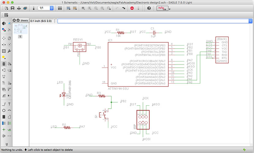
Schematic eagle prj file
After that we need to switch to the board using this tool  on the top bar menu
3. Make the board
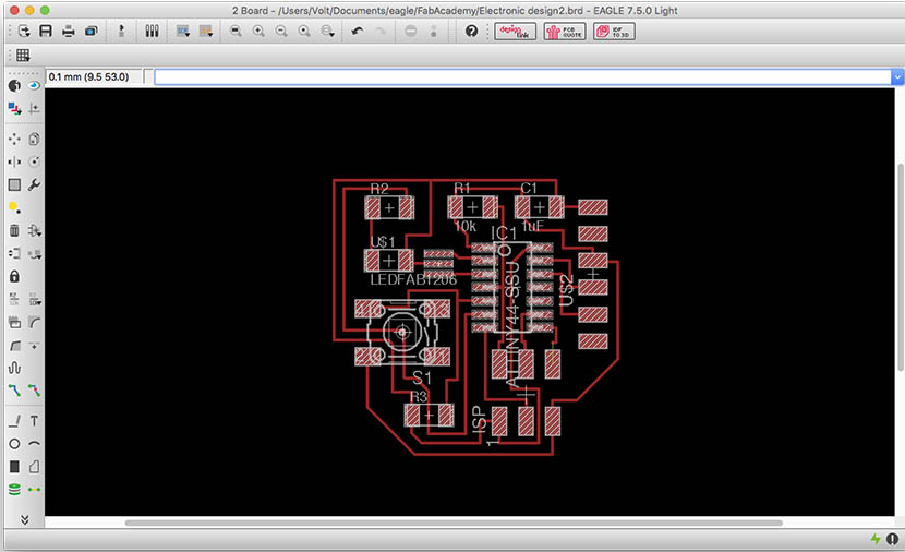
I've placed the components following more or less the Echo hello-world and just adding the led, button and resistors on the left, because on this side there are the two microcontroller's pins I need for those components. This is the result after i've placed all of the components:
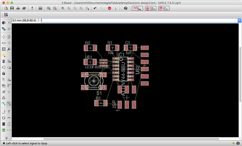
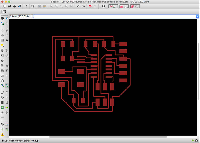
Then i've tried some attempts with the Autorouting  until I found a good setup. I needed some adjustments for traces, but at the end I've reached a good result.
Board eagle prj file
4. Export the DXF file
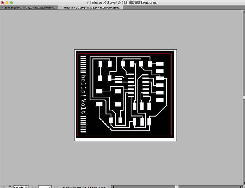
First of all I had to make visible just the pads and traces of my circuit, cause that's all we need for the production process with the fiber laser. Just a click on this button  on the left menu bar and a window pop-up: disable all and make visible just the "top" level. You should see just the pads and traces
Now we can export the file:
File (main top menu) > Export > DXF
5. Production and soldering
Using Adobe Illustrator i've prepared the file for the lasercut
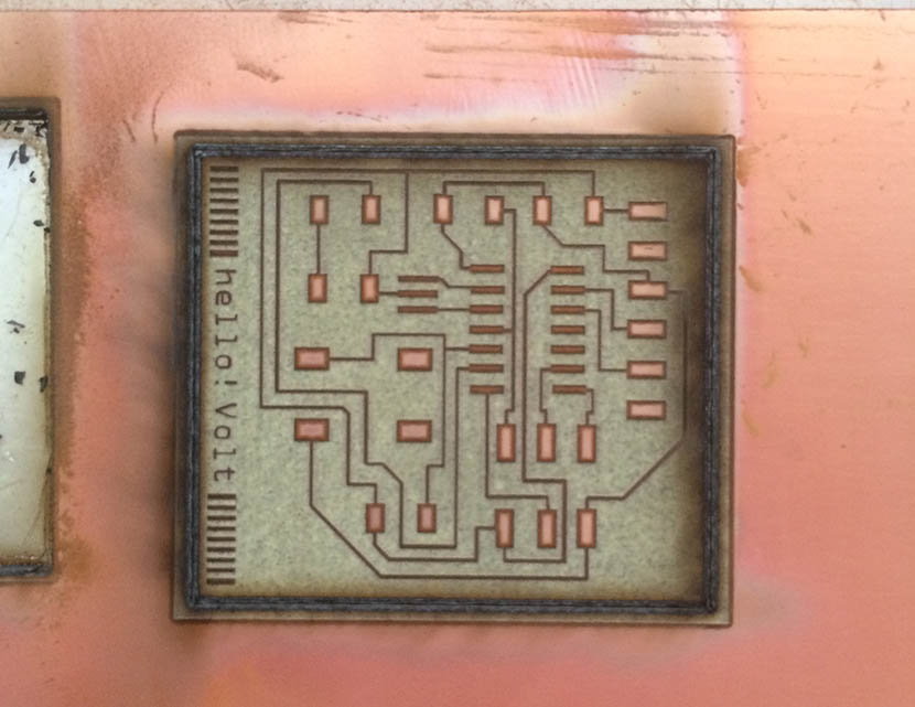
After that I've lasercutted it with the trotec (fiber)
After that I soldered all the components, and this is the result:
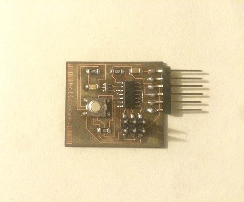 I ended to use the 16Mhz resonator, because i wasted the last 20Mhz one making a mistake soldering it, fortunately the pads were good for the 16Mhz one
6. The test
Go back in Home