As first step i burned the bootloader inside the main board using my Fab isp. After that I was able to use directly the Ftdi to plug the board and programming it with arduino IDE.
Inputs and outputs
The inputs of the board are:
- [A6 and A7] 2 x potentiometers for minutes and seconds setting
- [A1 and A2] 2 x push button for start the lamps and save/use timer setting (longpress/shortpress)
The outputs are:
- [pin 5 to 11] 7 segments leds
- [pin 2,3,4] 3 common anode of the displays
- [A13 and pin 13] 2 x pin relays
The code
I took advantage of some library in order to get the code working as I wanted. I used the EEPROM library and the wire library (for future implementation of the rf communication with the uv/pressure sensors board). The main resources I used:
EEPROM tutorial
Timer interrupts instructables
7 segments display tutorial
Included libraries

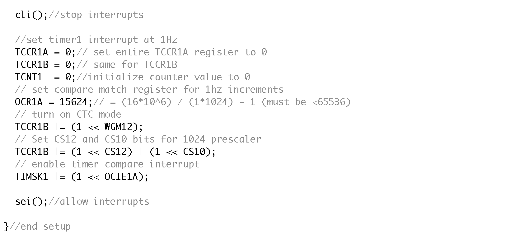
Timer interrupts (inside setup function). Setting the number on OCR1A you can set the frequency of the clock, in this case 1Hz (1 second):
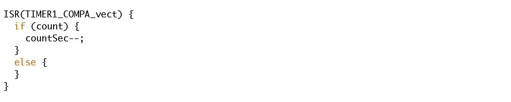
Timer interrupts function: this function starts once the start button is pressed, and run each seconds (cause of the 1Hz frequency we setted
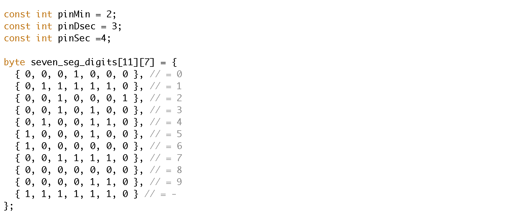
7 segments display: before the setup are defined the commone anode pins and inside an array the sequence of leds on and off to visualize each digit (0 = on | 1 = off).
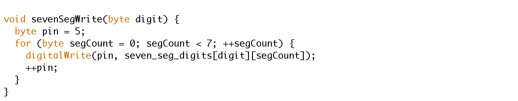
7 segments display function: a function is declared in order to visualize a digit passing the number as parameter of the function
3 displays multiplexer function: here using the function sevenSegWrite and turning on each common anode at once you get all the three digits displayed using just 7 pins for the leds

3 displays multiplexer function: this is how the function is used

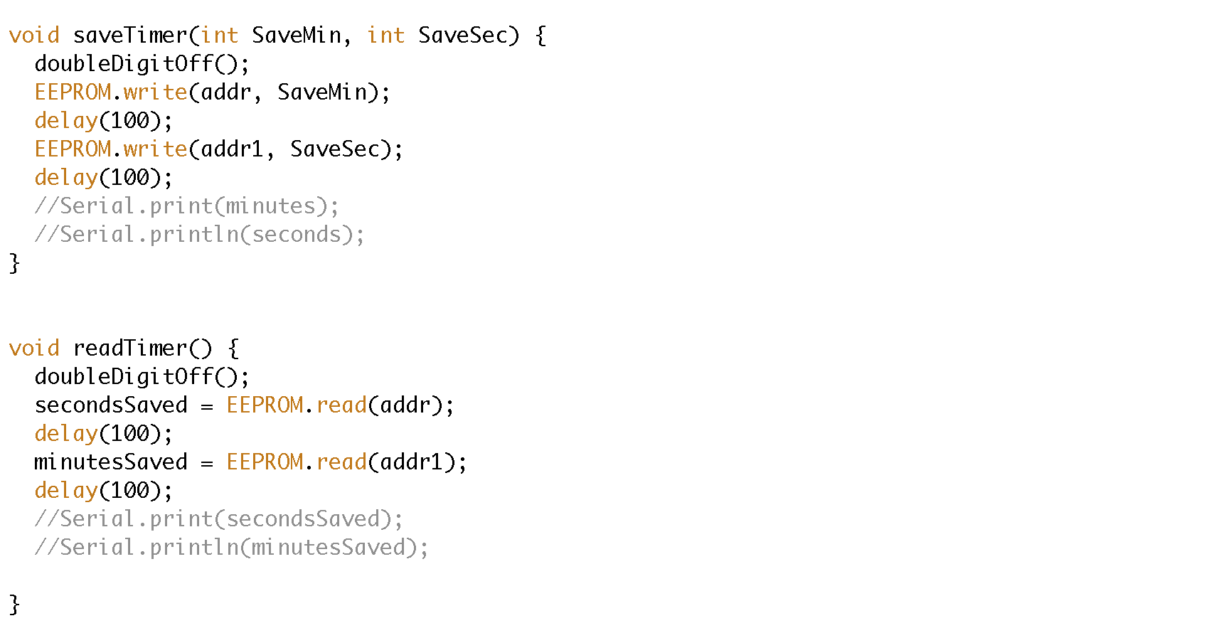
EEPROM save and read functions:
The result
Download the Arduino code
Go back in Home