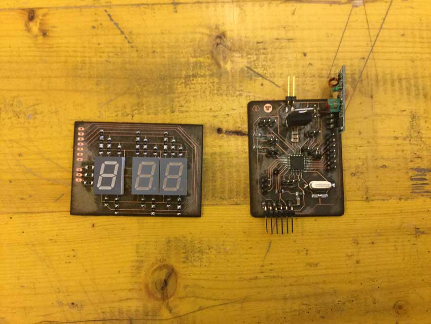
For the final prj I made two pcbs, one is the core of the project, it allows to set and start the timer and to save and reuse a timer set. As output it shows the timer through digits displays and control a relays module where uv lamps, safe lamps and vacuum pump are connected. The second board I made is a multiplexer board for 3 seven segments display, this allowed me to use just 10 digital pins (instead of 24) to control 3 x digits display.
The main board
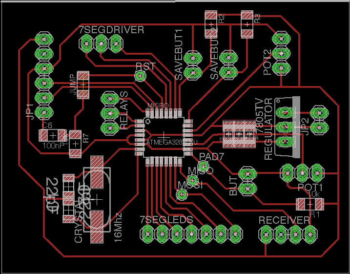
The main board has been designed starting from a satshakit micro. The main components are:
• Atmega 328P;
• 16Mhz Quartz clock;
• Voltage regulator to 5 volt;
• Rf receiver module (1 dig pin, gnd, vcc);
• FTDI compact headers;
• ISP single headers;
• 2x 1x3 headers for potentiometers (gnd, analog pin, vcc);
• 1x3 headers for relay controls (3x digital pins) This module;
• 2x 1x2 headers for 2 buttons (data and ground);
• 1x3 headers for common anode of the sev segs displays;
• 1x7 headers for sev segs display leds;
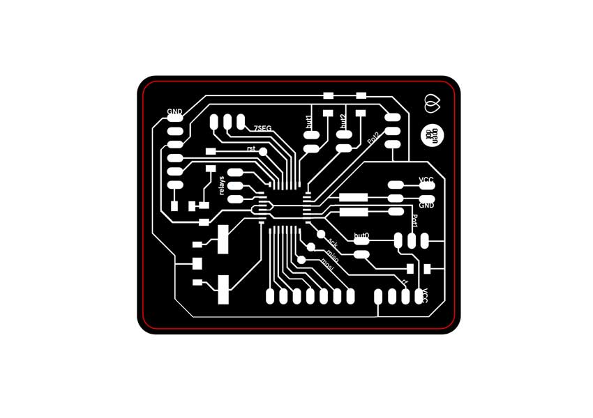
SVG file
Eagle files
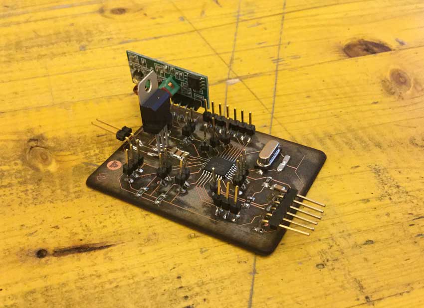
This is the result after i soldered the components:
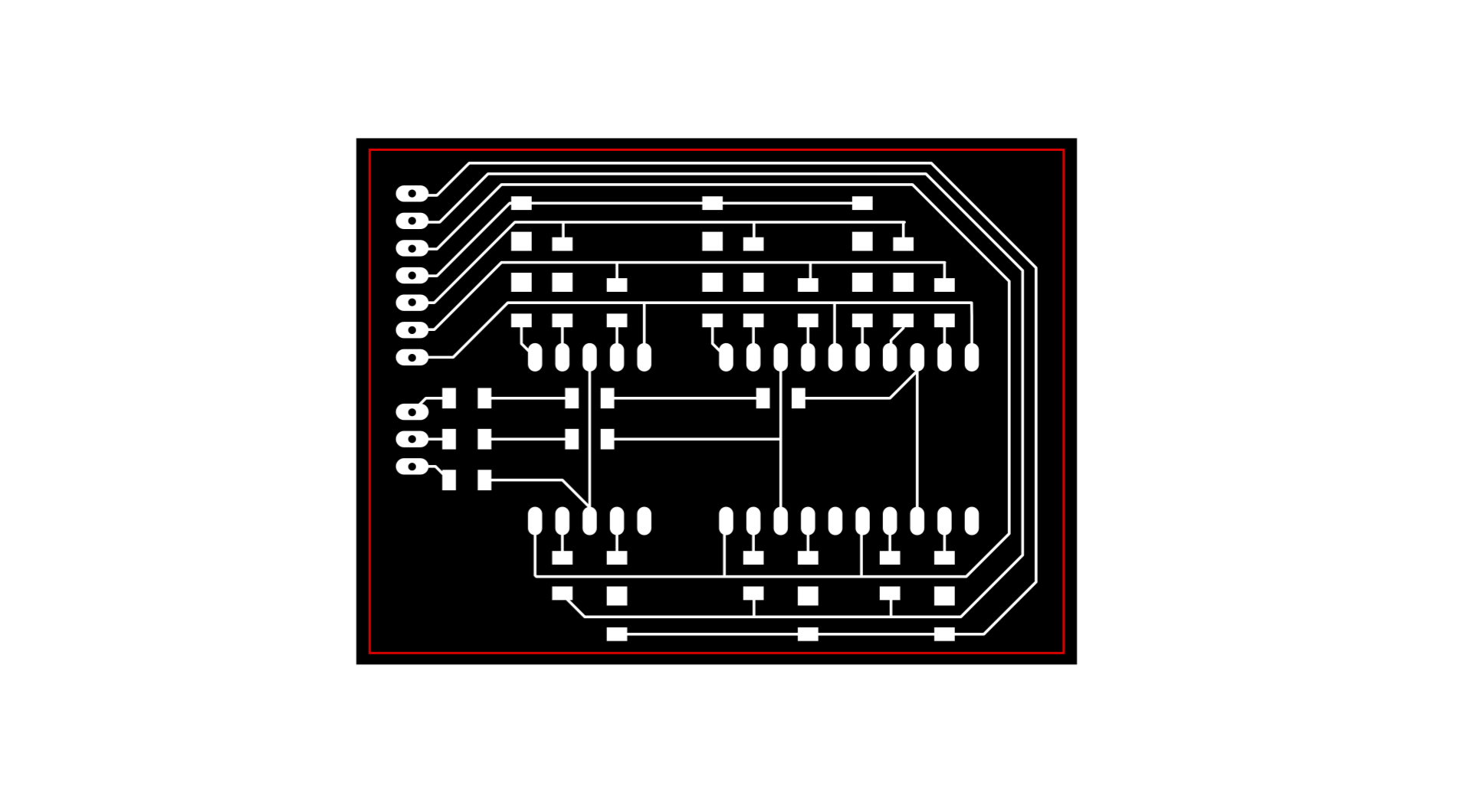
The 7segs display multiplexer board
In order to control 3 seven segments display with just 10 digital pins I had to make a pcb for it: the 3 common anodes of the displays are connected to three digital pins, and the 7 leds of each display are connected to the same 7 digital pins. Setting the pins connected to the common anodes on and off (HIGH and LOW) rapidly allows to see all the digits on the display thanks to the persistence of vision.
The components are:
• 3x 7segs displays (common anode)
• 3x 220ohm resistors
• 30x 0ohm resistors;
• 1x7 male header
• 1x3 male header
SVG file
Eagle files
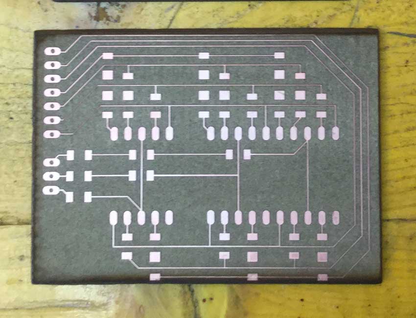
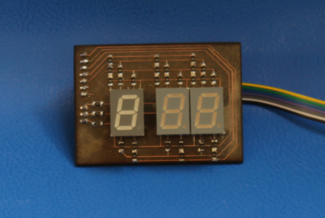
This is the result after i soldered the components:
 I milled the holes with a drill in order to have the headers on the other side of the board.
Go back in Home