
Week 13
Output Devices (Apr 27)
Assignment:
add an output device to a microcontroller board you've designed and program it to do something1. Sketches
For the Final project I want to use 2 servo motors to control ink tube movement. I plan to use Satsha kit for this
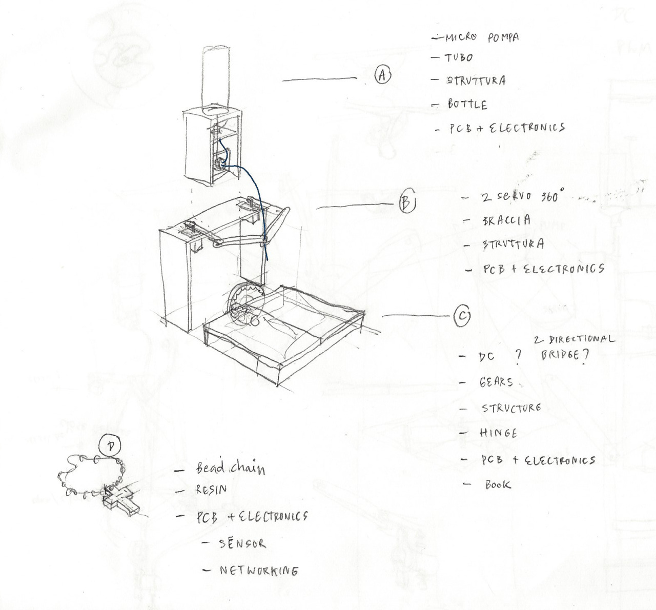
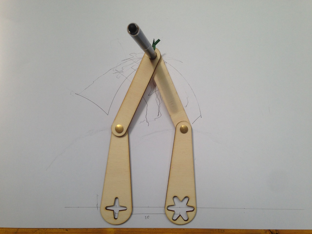
Right now 'll focus on the PART B. Manual test of arms movement. And the struture is ready for testing

2. Satsha kit
I've been struggling with Satsha Kit for some times.. my first 2 boards had short circuit and I have no idea why..
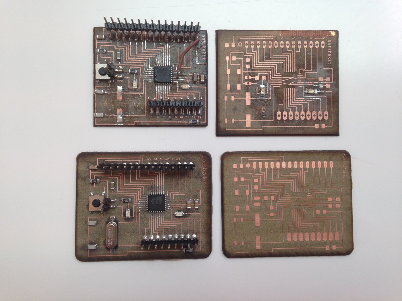
I wonder would it be that I soldered badly ? My board is lasered badly ?
Then with the 3rd Satsha, I discovered that when I finished solder it, there was no short circuit. But soon after I connect everything, the short circuit happens !
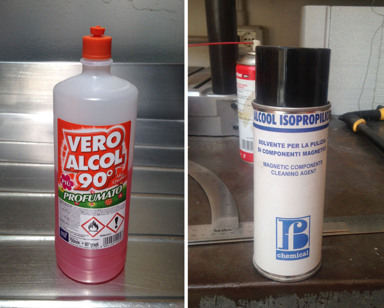
Since the connection seems correct, Enrico suggest that probably because solder problem.. One valid ipotesi is that I use the bad-quality solder flux !
I used the left most one which is quite old so it might have had created problems.
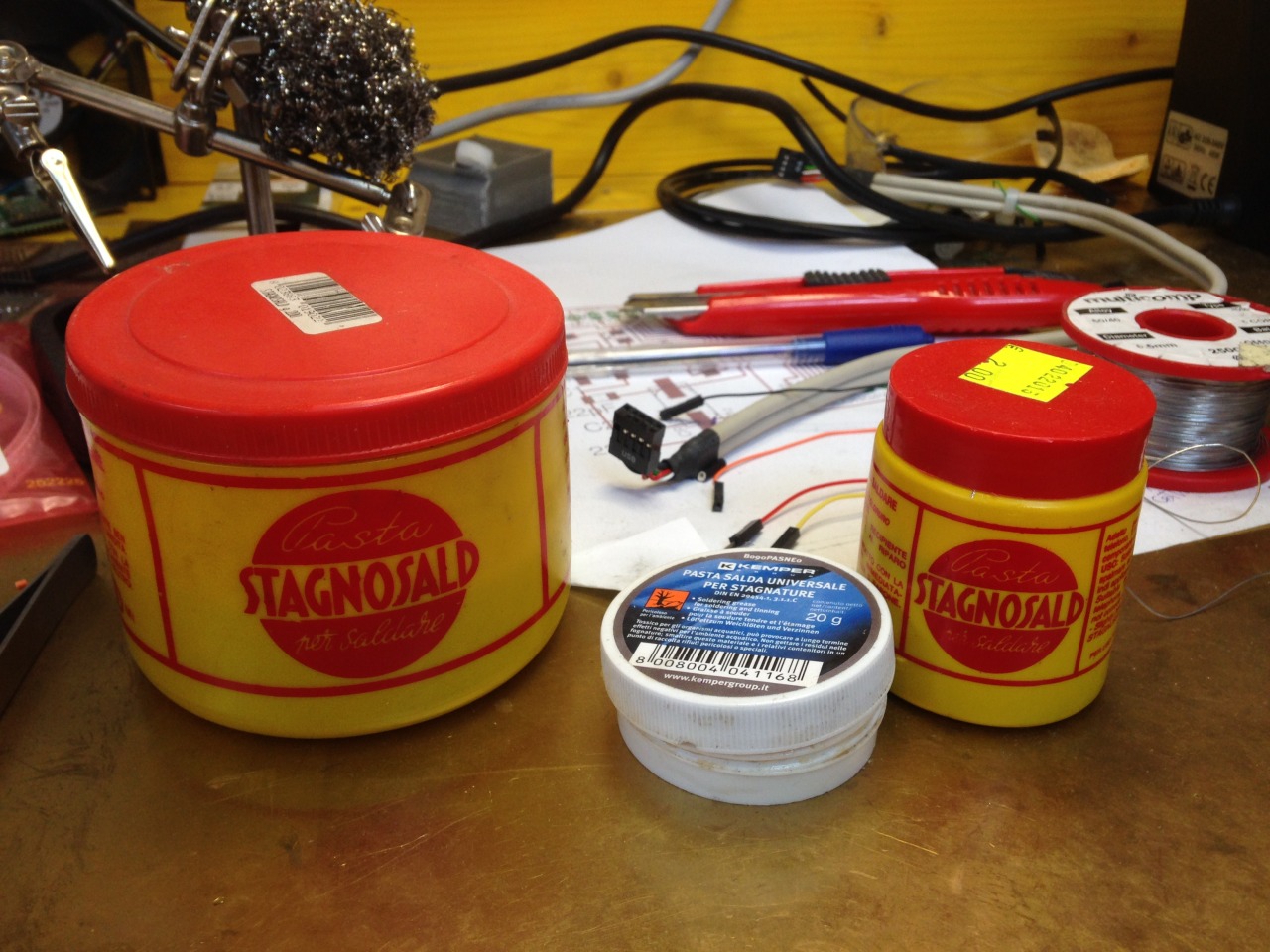

So Enrico helped me clean the PCB with alcol, cotton bud and cleaning spray.
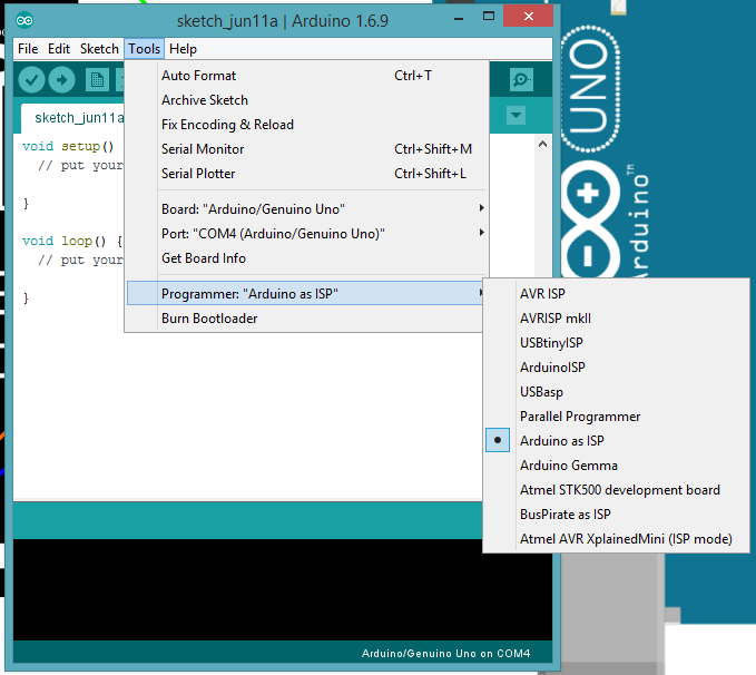
And there's no short circuit anymore. I use Arduino as programmer, following this connection scheme with Arduino
And.... it did program.

TestingI connect Satshakit with FTDI cable following this connection scheme
Up load blink sketch successfully !
3. Milling a connector board
Up until now at Opendot we had co2+fiber Laser to be used in electronic production but now we are left only with the milling machine Roland modela MDX-40A. So this is a new challange for me to mill a booard from zero.
- See detail and useful links here :
Since it is new we need to set up the Machine & software first. Manual (PDF) | generating gerber files from Eagle : tutorial 1 tutorial 2 | flatcam
I designed the board in Eagle and then use Fabmodules from browser to export gcode flies.


Export gcode file from Fabmodules


The bits : the right one for traces and the left for outlines miling

The first time I did z 0 badly and accidentally ruined the bit so the result came out pretty bad (the top-most one) so I changed the bit and make another board. Still the 0 z is too low (you can notice that the traces are more narraow than in the design ) but I think it is fine.

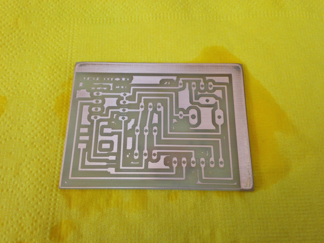
Stuff the board

4. Programming
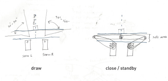
As one part of the final project, I want to test the movement of 2 servos which will be the arm structures for ink tube.The workflow is :
1. If Push button is pressed
arms starts moving randomly in the specific range.
2. if push button is relased
the arms close in order to give space for the movement of the book folding.
They must be limited the range in order to avoid the crashes.
In standby mode, the two arms have to be in safe erea to avoid crashing with the leg.
Successful test : push button -> servo motors
/*Connected with
   - push button as input
   - L, R servos with random
*/


#include <Servo.h>
Servo leftServo;
Servo rightServo;
Servo legServo;
int pos = 10;

const int switchPin = 2;
int switchState = 0;

long randNumber1;
long randNumber2;
long randNumber3;

int legState = HIGH;

void setup() {
  pinMode (13, OUTPUT);
  leftServo.attach(10);
  rightServo.attach(11);
  legServo.attach(6);
  leftServo.write(10);
  pinMode(switchPin, INPUT);
  Serial.begin(9600);
}

byte x = 0;

void loop() {
  Wire.beginTransmission(8); // transmit to device #8
  Wire.write(switchState);              // sends one byte

  Wire.endTransmission();    // stop transmitting

  switchState = digitalRead (switchPin);
  Serial.println (switchState);

  // start drawing

  if ( switchState == HIGH) {
    legState = LOW;
    Serial.print("draw_");
    leftServo.write(10);

    randNumber2 = random(30, 90);
    randNumber1 = random(90, 160);
    leftServo.write(randNumber1);
    Serial.println(randNumber1);
    rightServo.write(randNumber2);
    Serial.println(randNumber2);

    randNumber3 = random(200, 1500);
    delay(randNumber3);
    Serial.println(randNumber3);

  }

  else {
    leftServo.write(155);
    rightServo.write(25);

    if (legState == LOW) {
      for (pos = 10; pos <= 180; pos += 1) { // goes from 0 degrees to 180 degrees
        // in steps of 1 degree
        legServo.write(pos);              // tell servo to go to position in variable 'pos'
        delay(15);                       // waits 15ms for the servo to reach the position
      }
      delay (1000);
      for (pos = 180; pos >= 10; pos -= 1) { // goes from 180 degrees to 0 degrees
        legServo.write(pos);              // tell servo to go to position in variable 'pos'
        delay(15);                       // waits 15ms for the servo to reach the position
      }
      legState = HIGH;
    }
  }
}
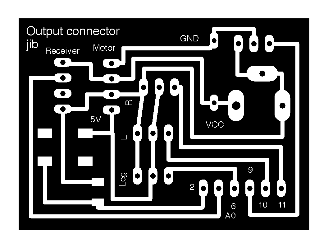
Download files : Connector board in Eagle : board (brd) | schematic (sch) | gcode for traces (nc) Connector board image : traces (png) | outlines (png) Program(ino)
<< previous | next >>