Download the boards files
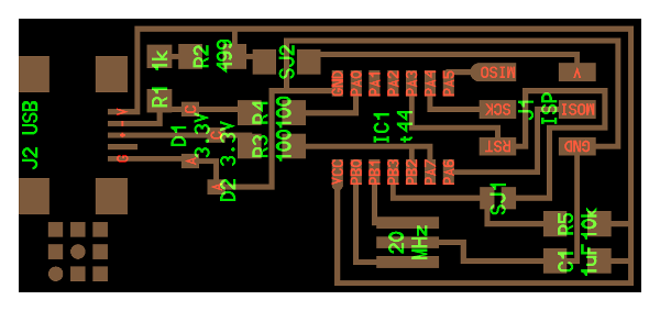
The programmer selected in Opendot is the hello ISP44 with 20 MHz resonator.
We were given the possibility to chose between the USB connector or a board edge USB connector. I decided for the USB connector which I find more practical and, in a way, more robust.
I downloaded the board traces but I couldn’t send it directly to the laser cutter since the size of the contacts of the 20 MHz Crystal had to made smaller to account for the size of the components that had been purchased.
Nicola, a team mate, had taken the time to document the right size of the traces and following his example I started modifying my design.
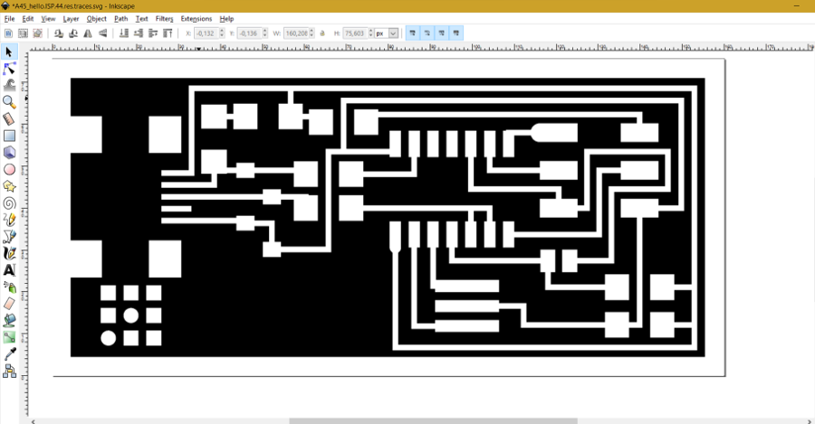
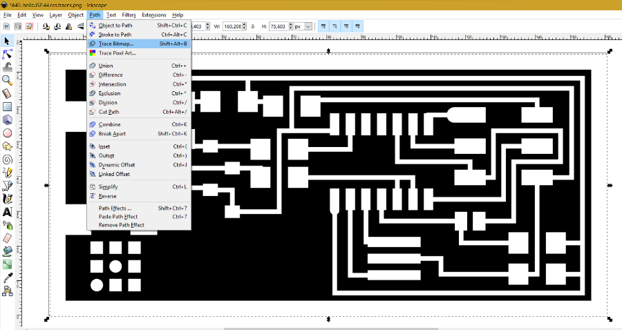
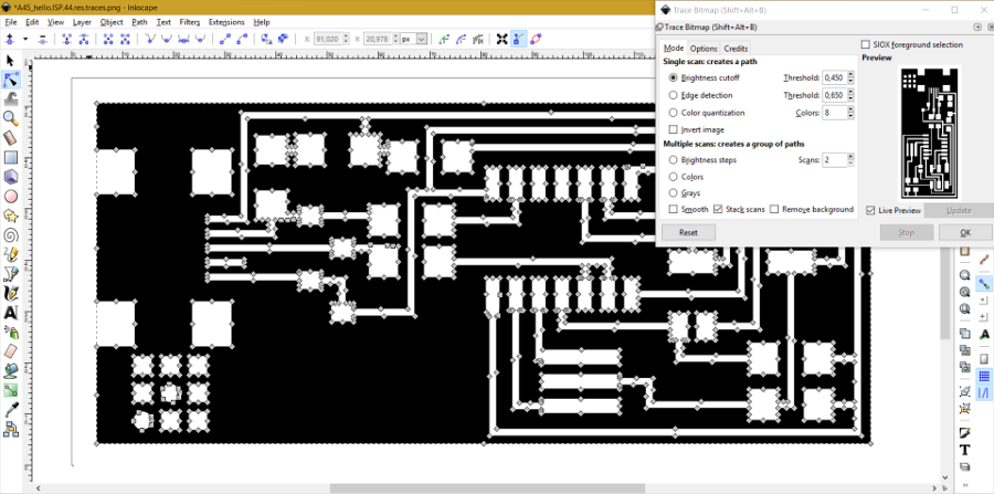
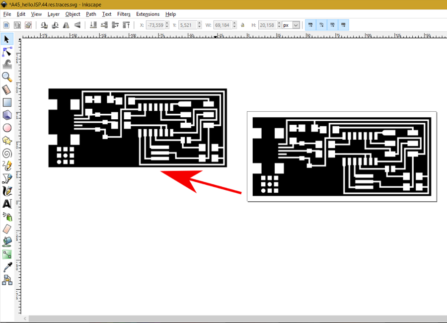
I opened my design in Inkscape to convert the PNG image in a vector image to be able to modify the size of the traces. To do this I took a quick Inkscape tutorial on YouTube
Inkscape Tutorial How to Convert Image to Vector Graphics (Trace Bitmap) by VscorpianC.
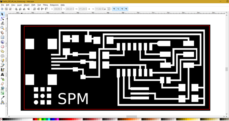
Here are the different steps I followed: import the PNG image, convert the PNG to vector image, move aside the vector image to delete the PNG, edit path by nodes, modify traces, final SVG file for cutting.
Laser cutting the PCB
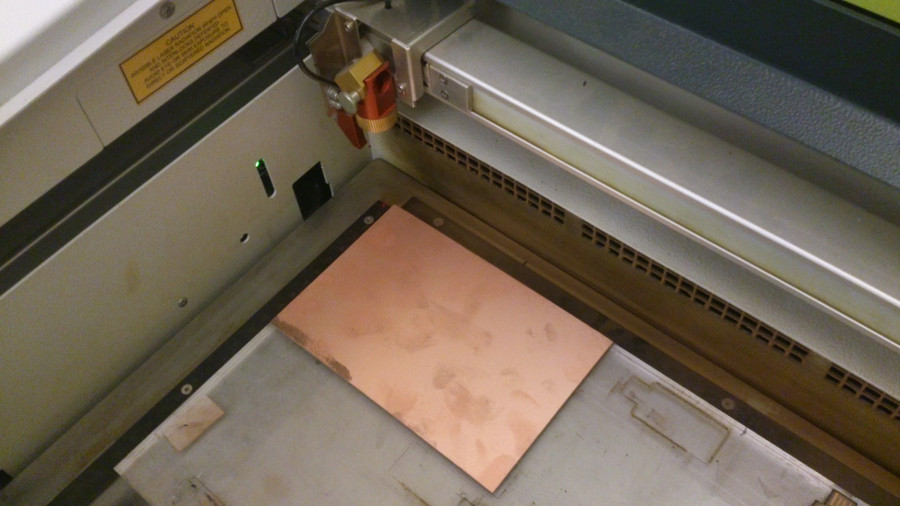
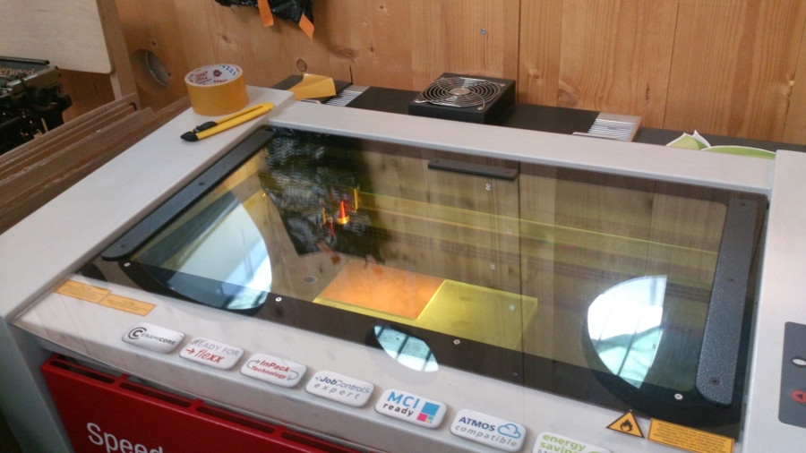
In opendot we have a CO2 / Fiber Trotec Speedy 100 flexx laser cutter. The machine is well described in the Electronics Production tutorial (
Laser Cutting a PCB with a CO2 / Fiber Trotec laser cutter).
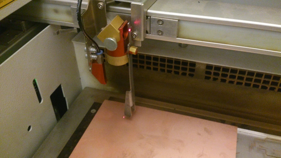
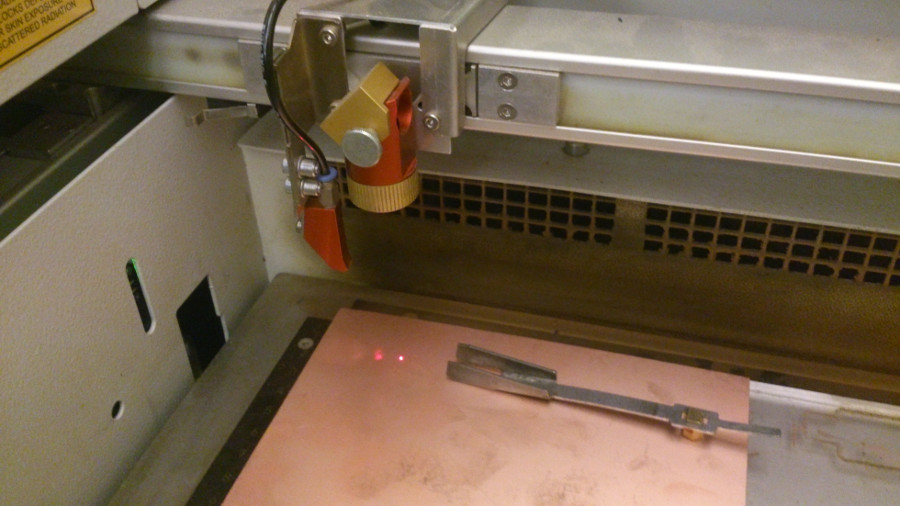
In order to use the machine it is necessary to set the correct distance between the laser head and the workpiece. I lowered the workpiece support and moved the head in the position where it will approximately start cutting. I then mounted the distance gauge.
I then raised the workpiece until it just got in touch with the gauge and made it fall.
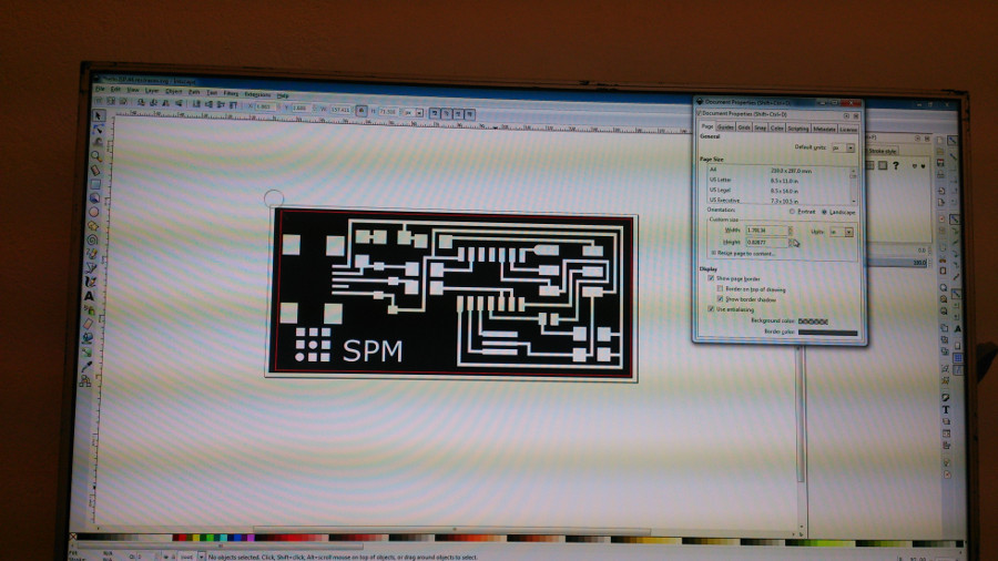
Now, having uploaded the SVG image in the computer connected to the laser cutter, I opened it in Inkscape and opened the document properties to show the board dimensions.
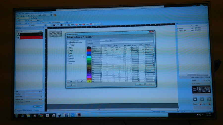
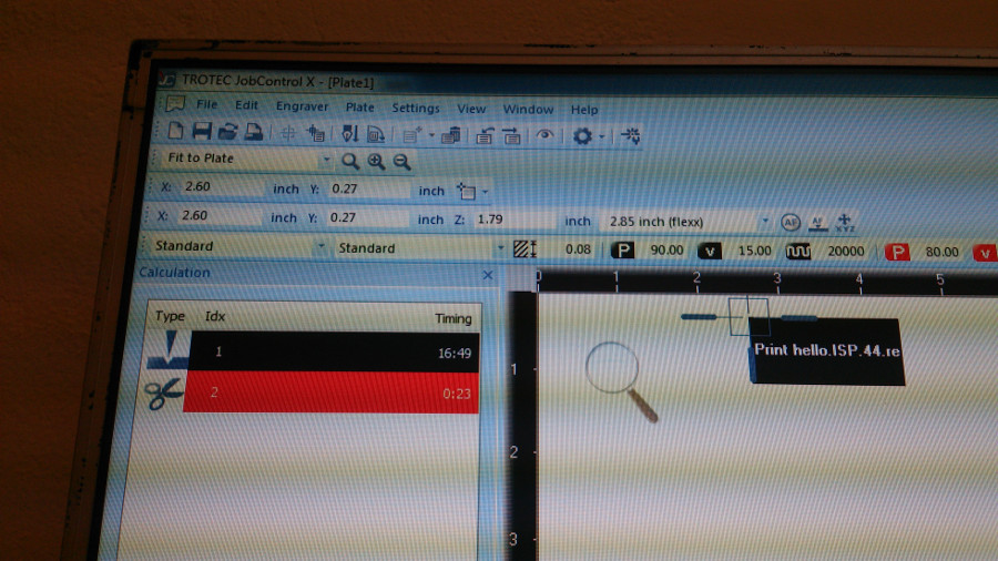
I then clicked on the print button. The file was transferred to the Trotec program. I checked the document properties and set dimensions to match the Inkscape image. I checked the cutting parameters for both Fiber (black images) and CO2 (red images). The settings were the same to the ones listed in the above tutorial.
The program displays the time it will take to cut the board, giving the duration for fiber and CO2 cutting. The time was approximately 17 minutes for the fiber and 25 seconds for the CO2.
Pressing the print button starts the machine.
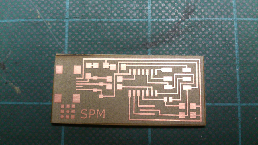
Here is the result. GREAT!
I then decided to print two more boards. Since I never soldered before I guess I may need more than one.
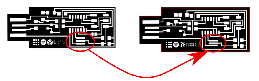
Printing the other boards turn out to a problem, Actually, they could not be cut with the CO2 laser. The engraving was excellent, though.
It took me a while, and the help of my teammates, to understand what was going on. Actually, I had redrawn the red contour to leave more material around the board. But the red line was now overlapping the copper and could not be cut. I took the red line back to the previous position and everything went beautifully.
Soldering
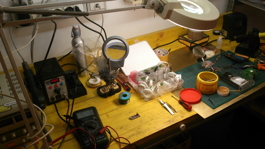
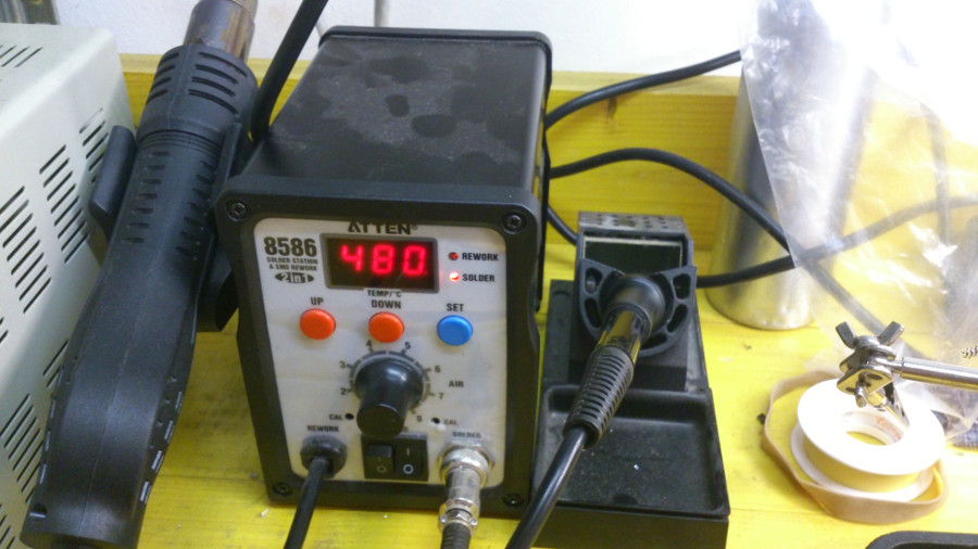
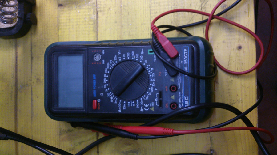
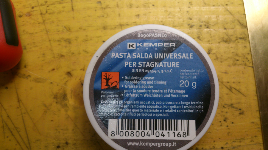
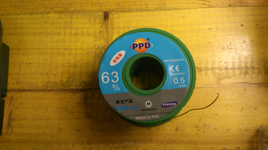
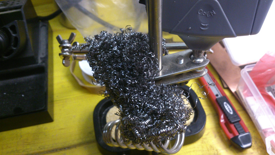
I set up the soldering space with everything I needed: soldering iron, multimeter, soldering paste flux, solder, soft coil tip cleaner.
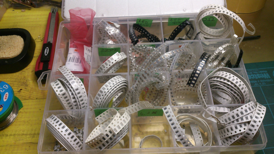
I then collected all the components:
- 1 ATTiny 44 microcontroller
- 1 Capacitor 1uF
- 2 Resistor 100 ohm
- 1 Resistor 499 ohm
- 1 Resistor 1K ohm
- 1 Resistor 10K
- 1 Resistor 10K
- 1 USB connector
- 2 jumpers - 0 ohm resistors
- 1 Resonator 20MHz
- two Zener Diode 3.3 V
- 6 male connectors
- one usb mini cable
- 6 wires with female connectors
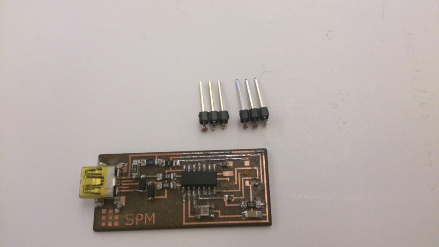
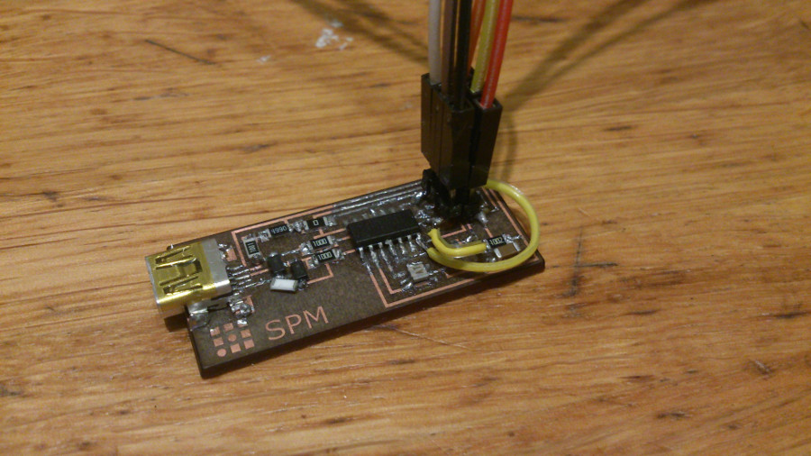
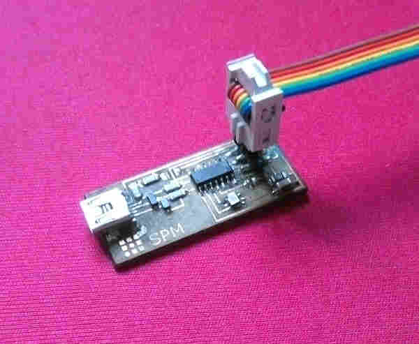
There we go! It wasn’t easy. Either I used too much solder or too little. Several times, the solder spread over nearby traces. Nevertheless, I started to enjoy it and after a couple of days finally I got my board completed and the smoke test right.
From zero to hero!
Programming the board
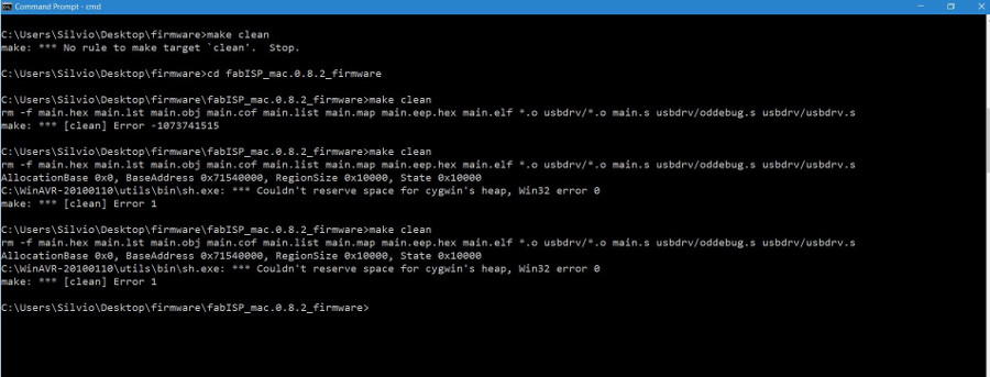
My computer runs Windows 10 and by following carefully the tutorial I had no problems until the “Program the FabISP” step. In fact, typing the “make clean” instruction I kept on receiving error messages I could not solve.
Moreover, plugging in and out the cables the connectors solder just broke, tearing away the copper from the board. I was really upset.
Nevertheless, this is sometimes the price you pay for learning and I fought back!
I decided to move to Ubuntu. Since I did not want to replace completely my current operating system, I tried to install Ubuntu alongside Windows 10. Unfortunately, the new operating system could not install. I investigated the solution in the Ask Ubuntu site. Here is the link: Installing Ubuntu on a Pre-Installed Windows with UEFI.
Since the issue looks complicated and I did not want to spend too much time, now, I chose to run Ubuntu directly from a DVD without installing it at all.
Happily, I could follow all the instructions without any problem.
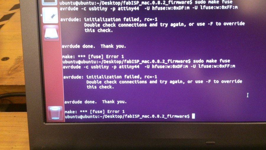
But programming was not over yet. Now I was forced to a halt at the “make fuse” instruction.
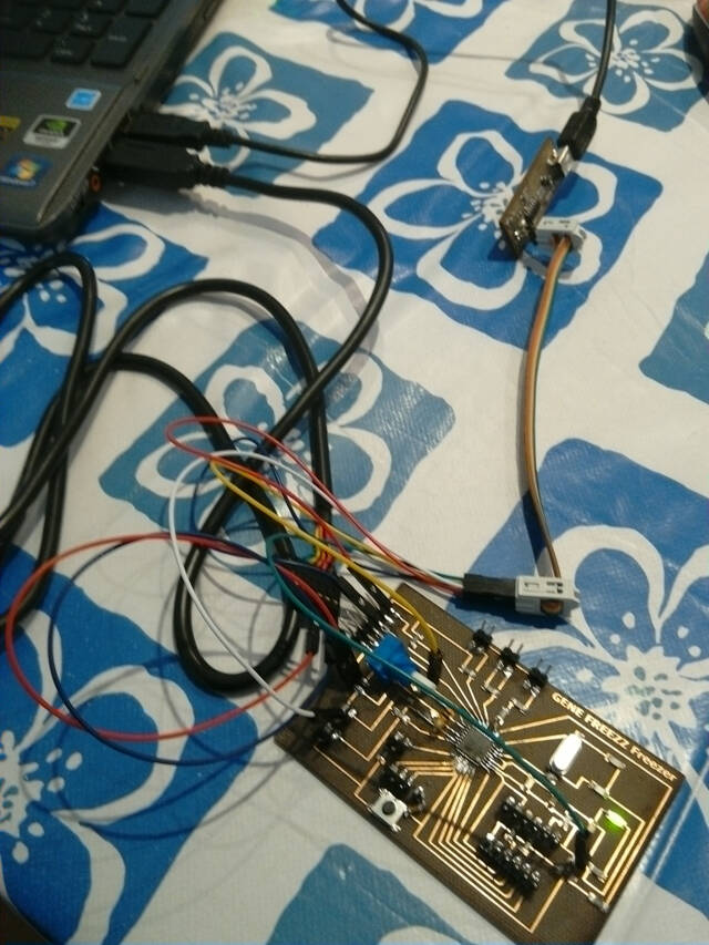
I started checking over and over the board circuits and, with the help of Andrea, a teammate who has a good experience in DIY electronics, we fixed a couple of short circuits, bridging with wires the damaged traces.
Unfortunately, we couldn’t manage to make the board recognized by the programmer (we used both our tutor Fab ISP and an ratavrisp2 programmer) so I resolved to build, in the next days, another board.
I did not finished yet the assignment but certainly, I learned a lot. And this is what I expected from the Academy.
Programming the board - 2nd tentative
In the previous assignment I had laser cut some spare boards and, this time, soldering became somewhat more natural. Nevertheless, when it came to programming, I kept receiving the alarming rc=-1 error.
Discussing the issue with my teammates, it seemed that those using Mac had far less troubles. And in fact, going through the different steps with Ernesto, another student, using hif Fab ISP and his Mac, solved all the issues. The board was now programmed though I could not get it recognized on my PC. I will need to take the time to check everything carefully once again, starting from the software installation.
During the assignment of week 8 - Embedded programming, I reviewed the toolchain and completely reset the software on my pc. I was then able to program the Fab ISP and all subsequent boards. In the first part of that assignment (lecture 8 - Toolchain) I give a detailed description of the steps I took.