Recap
The Electronics Production assignment had left an important open issue: I could not program the Fab ISP with my means. Moreover, not being able to get my Fab ISP recognized by my PC would not lead me much far on this new assignment.
I needed to to review in details the information acquired during the electronics lectures and go through all the steps once again.
Since I enjoy studying, I got myself some additional material to focus on, notably two very interesting books: “Make: AVR programming” by Elliot Williams and “C All-in-One Desk Reference for Dummies” by Dan Gookin.
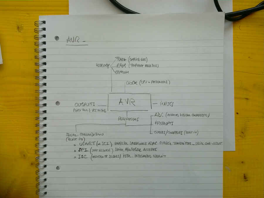
Recap AVR structure
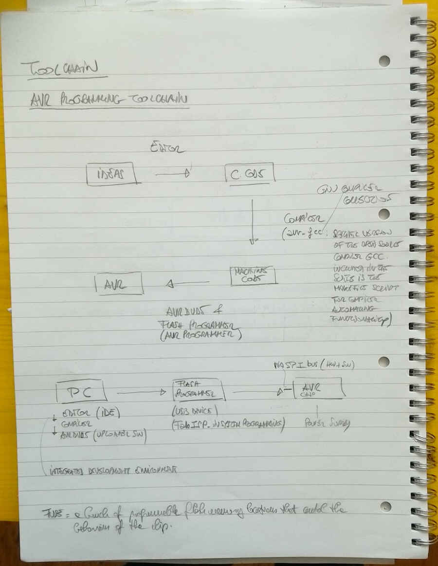
Recap the toolchain
These are the steps I followed:
- Uninstall WinAVR.
- Go back to a restore point prior to the previous software installation.
- Repeat the Windows Software/Drivers instal. When prompted to change PATH variable during WinAVR installation, so that make, avr-dude and avr-gcc are available without the need to type the full pathname, I confirmed.
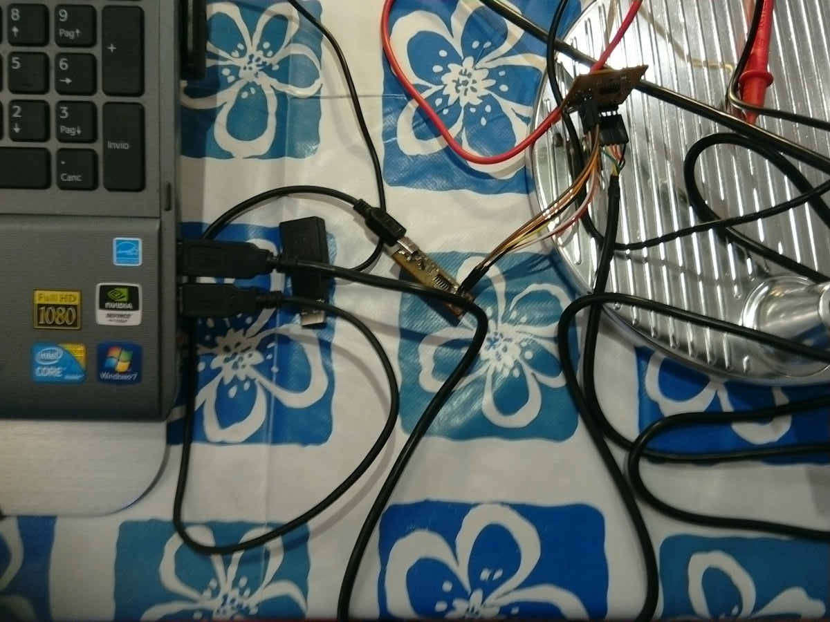
- Check the solder status of the FabISP and Hello Board (the 6 pin headers had become loose and the LED on the Hello Board had burn out).
- Hookup and check pin correspondence (VCC, GND, MOSI, MISO, SCK, RST).
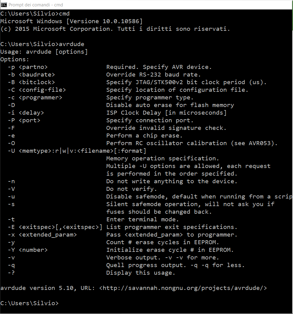
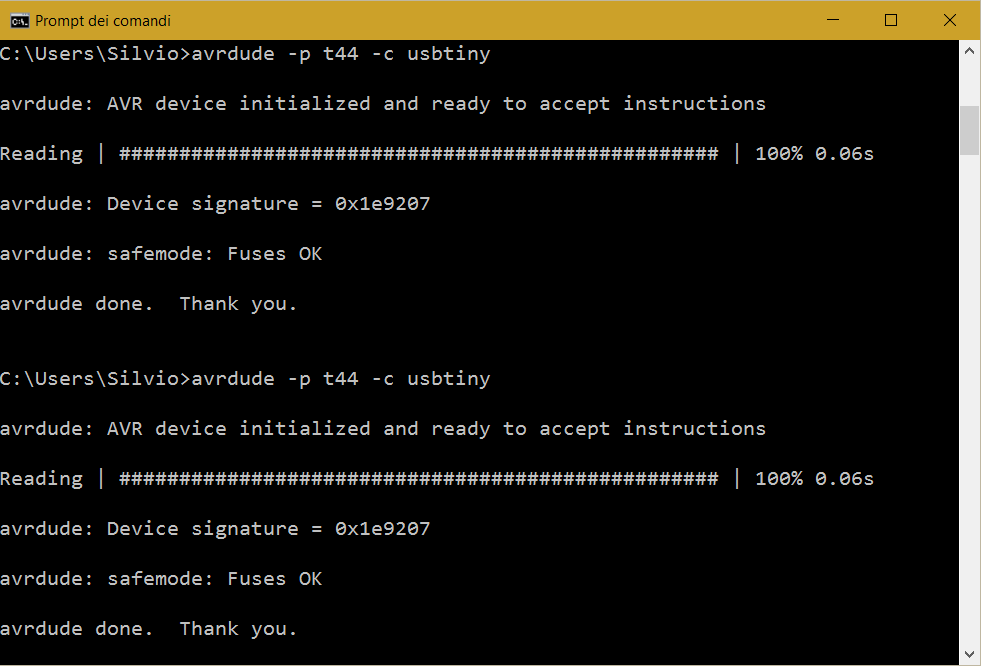
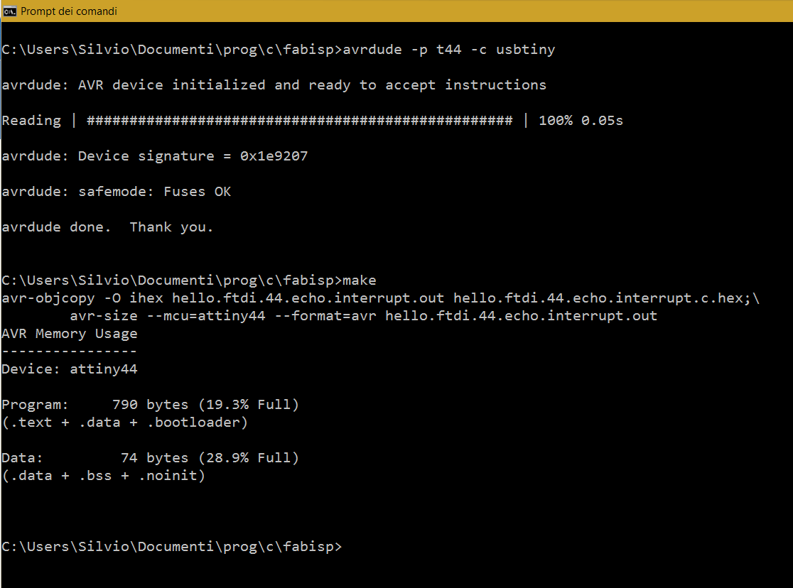
- Test AVR connection.
- Talk directly to the programmer.
- Launch a makefile (I tried with the echo.interrupt program).
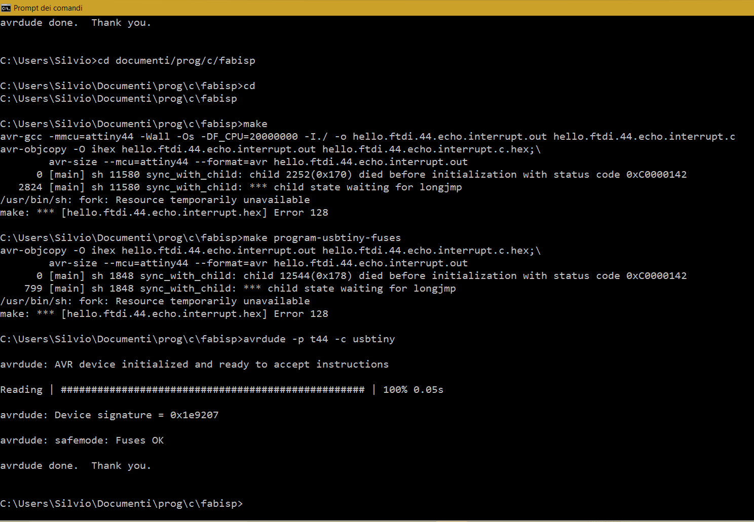
I run a Make instruction from the same folder where I had placed the C program and the Makefile.
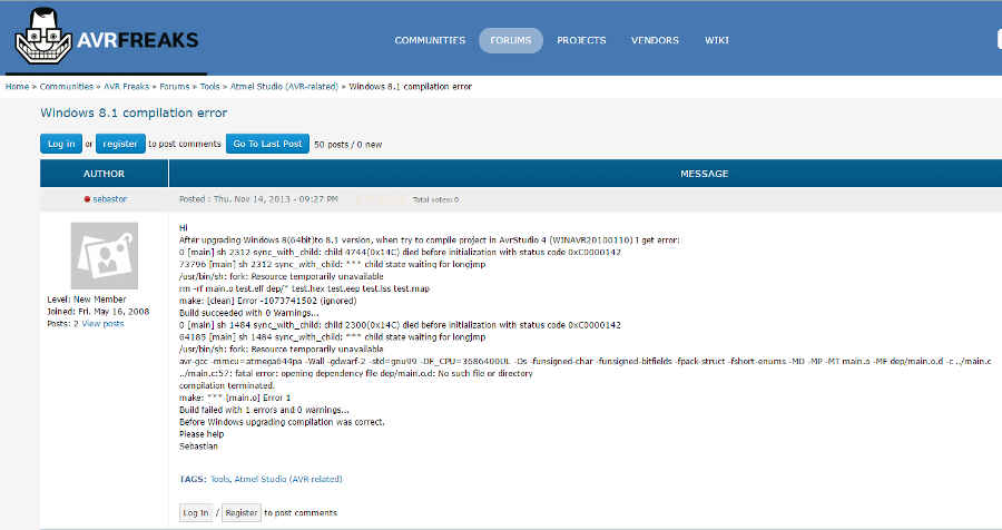
The result was an error: “... died without initialization with status code 0xC0000142”.
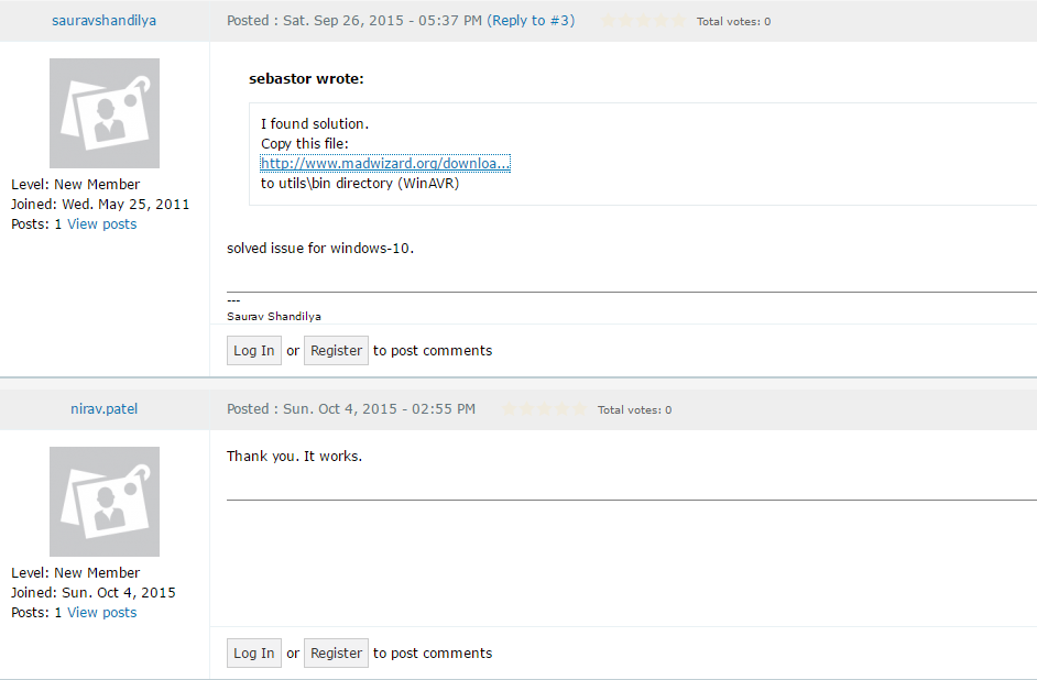
I searched the web and found the following solution in the AvrFreaks-Atmel Community:
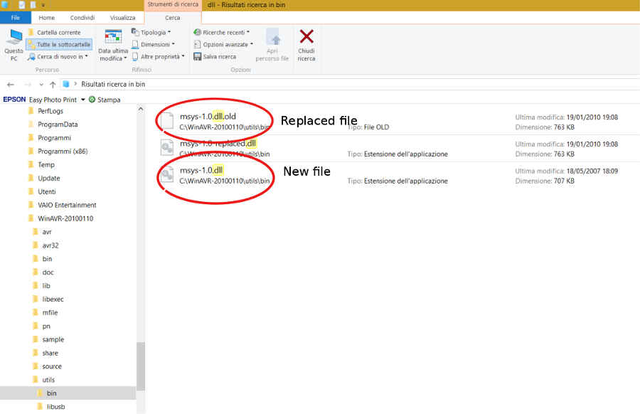
I replaced the msys-1.0.dll file in the WinAVR-20100110/bin directory.
Hopefully, when I run again the Make instruction, the error had disappeared!
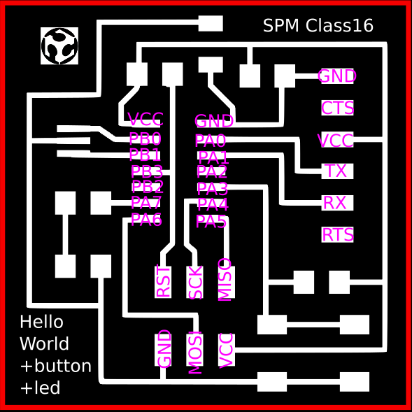
Now that the tool chain is working, I started programming my Hello World board.
Button and blinking lights
In order to program in "C" I found it extremely useful to well understand the following intriguing concepts:
- The way the register works (check the register summary on the AVR datasheet);
- How to enable any given pin for output by setting the data-direction registers (DDR) to one for the corresponding pin (by default all pin are set for input, ie. 0);
- How logical operators perform on register bits to set the output voltage on (1) or off (0) on a given pin:
- Set a bit (pin) “i” with OR: Byte |= (1 << i); note that the byte represents the PORTx register address;
- Clear a bit (pin) “i” with AND + NOT: Byte &= ~(1 << i);
- Toggle a bit (pin) “i” with XOR: Byte ^= (1 << i).
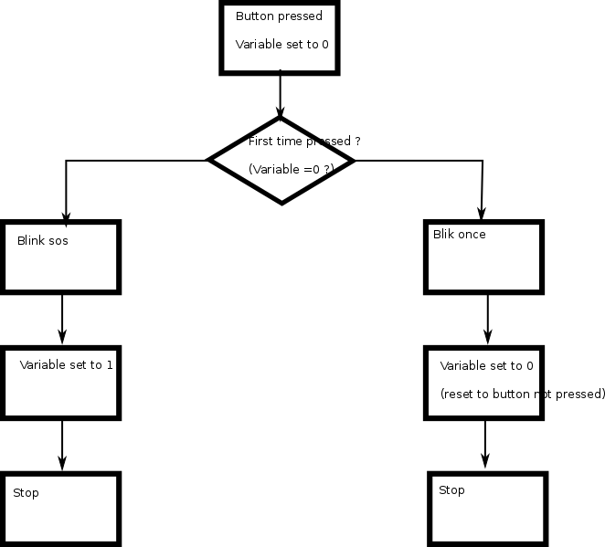
I decided to write a simple program in C that makes the LED blink in two different patterns: when I press the button the first time after powering the board and when I press the button a second time. The cycle then starts all over again. This is the program logical scheme:
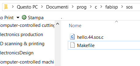
Check the toolchain files:
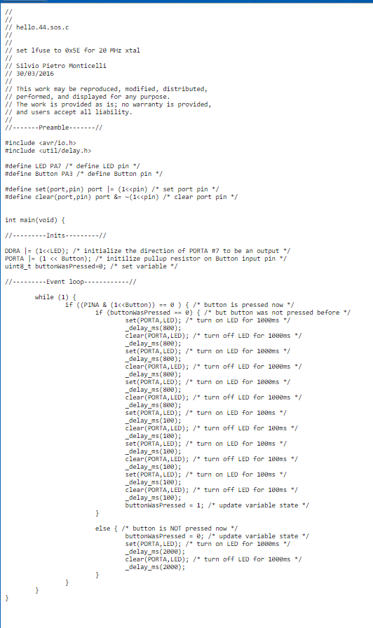
Certainly, there should be more elegant ways to display a repeating instruction like in the sos script. Anyway, at this stage, I kept it as simple as possible.
This is the program:
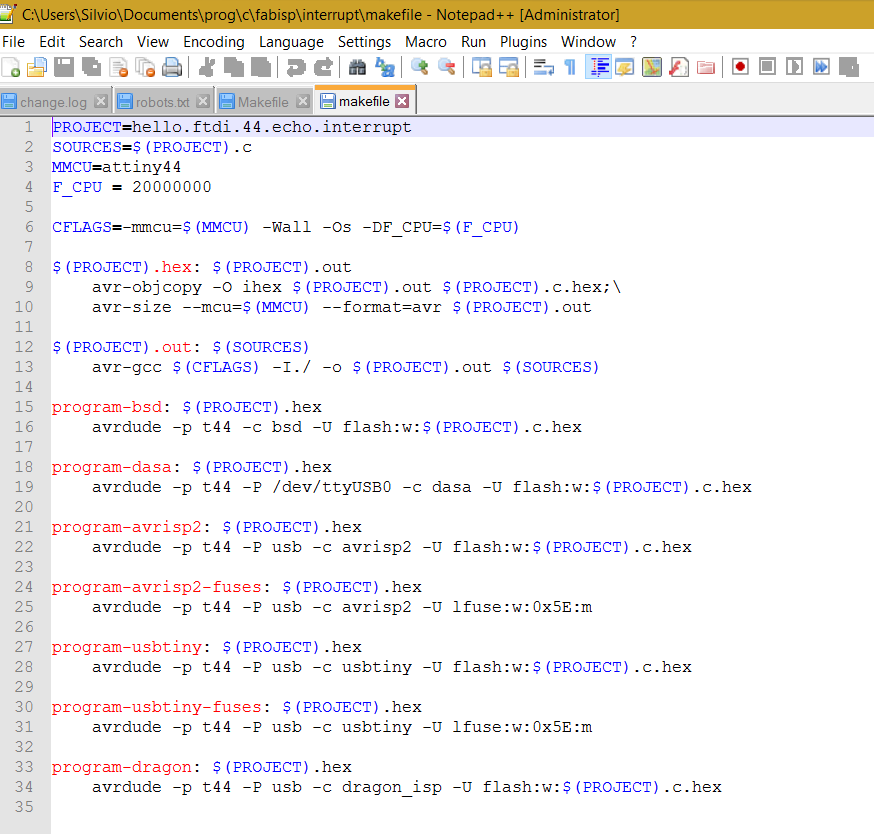
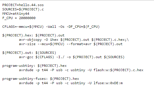
And this is the Makefile
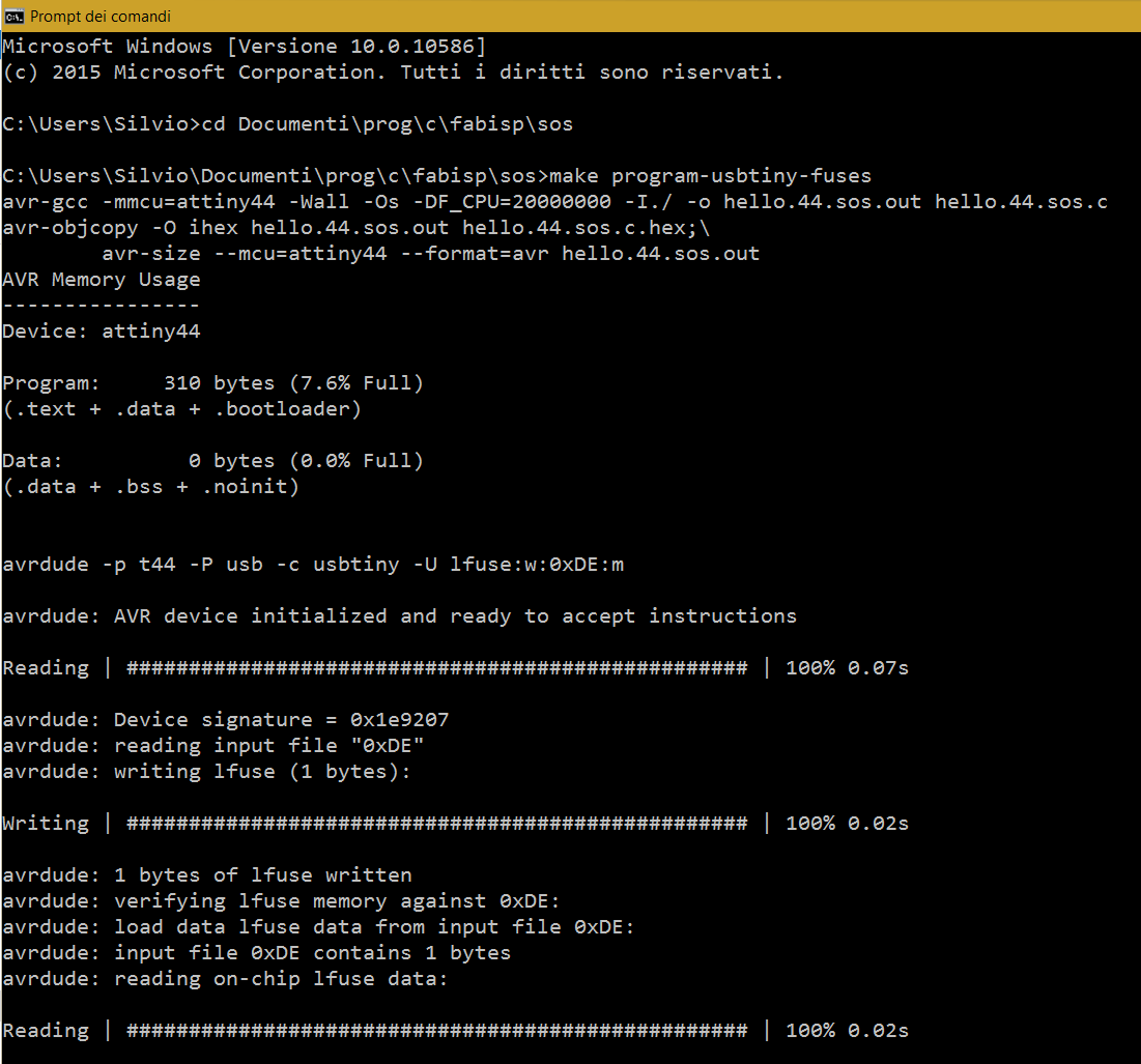
I then run the make instructions in the terminal, from the folder with the .c program and the makefile:
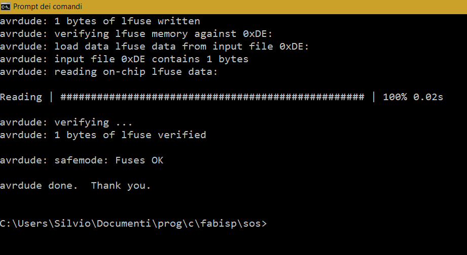
- Make program-usbtiny-fuses: to set the correct fuses configuration. The source code (C program) is compiled into machine code.
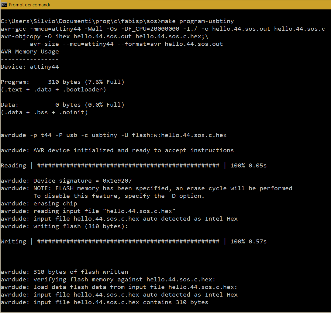
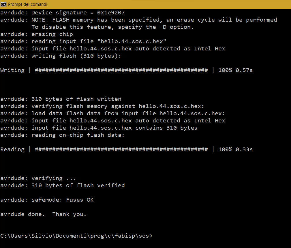
- Make program-usbtiny: the machine code is sent to the AVR.
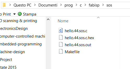
Here is what happened in the program folder:
Make fuse
Make program
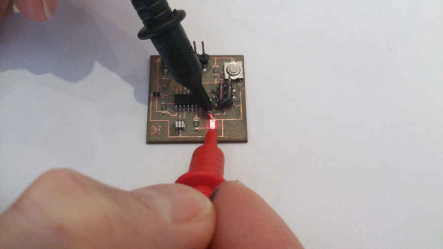
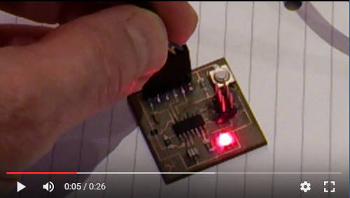
Here is the result on the board (click on the picture to see the video):