Week #16 NETWORK AND COMMUNICATION
Assignment
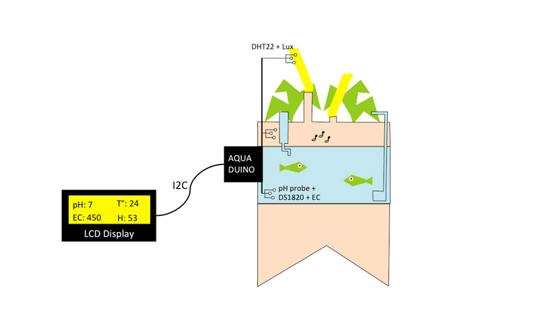
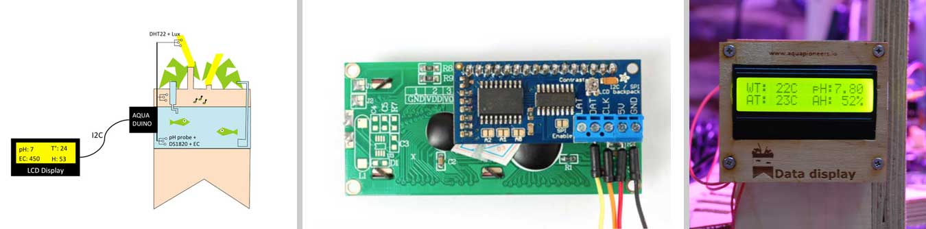
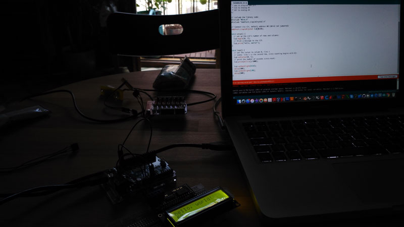
This week, I decided to play with a LCD panel to display the inputs data connected to the Aquaduino. This assignment will leverage:
- The Inputs week assignment where I was able to read each sensor value on the Arduino serial monitor and
- The Outputs week where I display "Hello world" to a LCD 16x02 display
Displaying Aquaponics inputs on 16 x 02 LCD display with the help of the I2C bus.
Why using I2C bus with a LCD display ?
Normally, to use a 16 x 02 LCD display with Arduino, you would need 6 pins: RS, EN, D7, D6, D5, and D4 to talk to the LCD. If you are doing more than a simple project, you may be out of pins using a normal LCD shield.
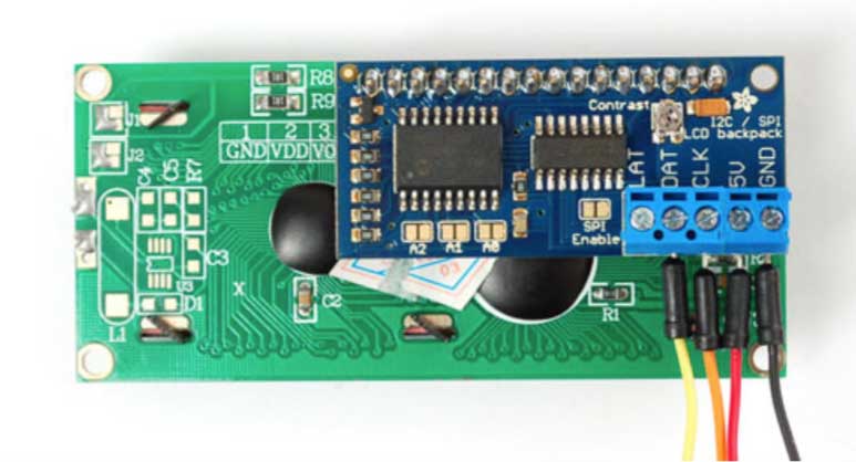
However, by using a I2C interface LCD module (i.e. also called I2C backpack), you only need 2 lines (I2C) to display information. If you already have I2C devices in your project, this LCD module actually uses no more pins at all. This unit connects with 4 wires including Vcc and Gnd.
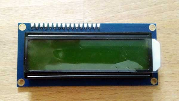
Which LCD to Use ?
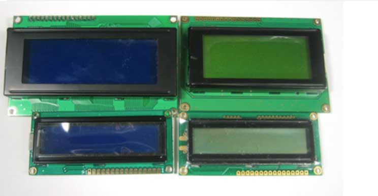
The backpack will work with any 'standard'/'classic' character LCD, however It does not work
with graphic LCDs. Character LCDs come in sizes ranging from 8x1 (8 characters, one line) to 40x4 (40 characters, four lines). The backpack will also only fit LCDs that have a single line of pins at the top, not the ones that have a 2x10 or 2x8 connector on the side. Those are much rarer these days but just keep a look out for that! The backpack will work with RGB LCDs (but wont control the RGB backlight, you can do that seperately from the LCD control) and it won't work with 40x4 LCDs because they have a second Enable pin.
In my case I decided to use a LCD 16X2 SPLC780D. See datasheet here.
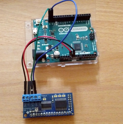
Schematic and library installation
Connect:
- DAT (SDA) to I2C Data: on the Leonardo could be digital 2 or SDA
- CLK (SCL) to I2C Clock on the Leonardo could be digital 3 or SCL
To begin reading sensor data, you will need to download Adafruit_LiquidCrystal library from github repository.
STEP 1: Get I2C address of my backpack module
Before we can use the I2C module, we need to find out it’s HEX address so we can communicate with it. We find the I2C module address by running this “I2C Scanner” sketch on our Arduino :
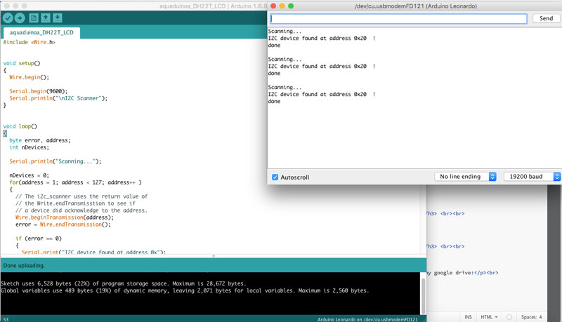
As you can see in the picture above, the address for our I2C module is 0X20, so I will use that value in the Sketch to communicate with it.
STEP 2: Load Demo "Hello World I2C" to test I2C bus
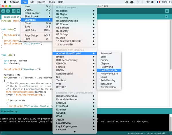
Upload the sketch. You should see the backlight turn on when the Arduino resets. If you don't see any characters, adjust the Contrast trim potentiometer with a mini-screwdriver until you see the text clearly The default HelloWorld sketch blinks the backlight as well as updating the text. If you see the backlight blinking that means your connection to the i2c port is OK but the contrast is too low or too high, or the LCD data pins are not solidly connected.
STEP 3.1: Merge 2 sketches: "LIQUIDCRYSTAL HELLO WORLD" + "DS18B20"
During the Inputs week I read the DS18B20 water temperature sensor (in celsius) to the serial monitor with the following skecth
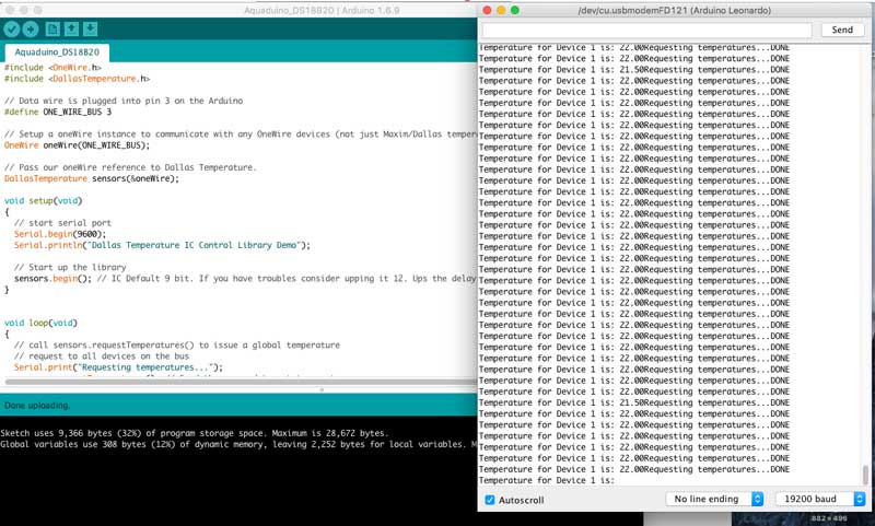
The next step will be to merge this code with the code for the I2C LCD.
#include "Adafruit_LiquidCrystal.h"
#include "OneWire.h"
#include "DallasTemperature.h"

// Data wire is plugged into pin 10 on the Arduino
#define ONE_WIRE_BUS 10

// Setup a oneWire instance to communicate with any OneWire devices (not just Maxim/Dallas temperature ICs)
OneWire oneWire(ONE_WIRE_BUS);

// Pass our oneWire reference to Dallas Temperature.
DallasTemperature sensors(&oneWire);

// Connect via i2c, default address #0 (A0-A2 not jumpered)
Adafruit_LiquidCrystal lcd(0x20);


void setup(void) {

  // Start up the Dallas library
  sensors.begin(); // IC Default 9 bit. If you have troubles consider upping it 12. Ups the delay giving the IC more time to process the temperature measurement

  // set up the LCD's number of rows and columns:
  lcd.begin(16, 2);
  lcd.setBacklight(HIGH);

  }

void loop(void) {

  /* DS1820 */

  // call sensors.requestTemperatures() to issue a global temperature
  sensors.requestTemperatures();
  int wt = sensors.getTempCByIndex(0);

  // display values
  lcd.setCursor(0, 0);
  lcd.print("WT:");
  lcd.setCursor(4, 0);
  lcd.print(wt);
  lcd.setCursor(6, 0);
  lcd.print("C");

}
The output of that sketch is the video that you can see below.
STEP 3.2: Merge 2 sketches: "LIQUIDCRYSTAL HELLO WORLD" + "DHT22"
// include the library code:
#include "Wire.h"
#include "Adafruit_LiquidCrystal.h"
#include "OneWire.h"
#include "DHT.h"
#define DHTPIN A0
#define DHTTYPE DHT22


// Connect via i2c, default address #0 (A0-A2 not jumpered)
Adafruit_LiquidCrystal lcd(0x20);


DHT dht(DHTPIN, DHTTYPE);


void setup(void) {
   // set up the LCD's number of rows and columns:
  lcd.begin(16, 2);
  lcd.setBacklight(HIGH);


 }
void loop(void) {

  /* DHT22 */

  int h = dht.readHumidity();
  int t = dht.readTemperature();
  lcd.setCursor(0, 1);
  lcd.print("T:");
  lcd.setCursor(3, 1);
  lcd.print(t);
  lcd.setCursor(5, 1);
  lcd.print("C");
  lcd.setCursor(9, 1);
  lcd.print("H:");
  lcd.setCursor(12, 1);
  lcd.print(h);
  lcd.setCursor(15, 1);
  lcd.print("%");

}
STEP 3.3: Merge 2 sketches: "LIQUIDCRYSTAL HELLO WORLD" + "PH"
STEP 4: Reading multiple sensors inputs
Now it's time to get things serious! As initially planned for my final project, I wanted to display several inputs value at the same time such as
- Water temperature
- pH
- Air humidity and Temperature
- Light intensity
- Electro-conductivity
/*
 # Aquiduino v0.1 code used to display using I2C bus analog pH meter + DHT22 + DS1820
 # Editor : Guillaume Teyssie // Fab Academy 2016 @ GreenFabLab
 # Ver    : 1.0
 # Date: 17/06/2016
*/


// Importing libraries
#include "Adafruit_LiquidCrystal.h"
#include "OneWire.h"
#include "DallasTemperature.h"
#include "Wire.h"
#include "DHT.h"

// Sensors pin allocation o the Arduino
#define ONE_WIRE_BUS 10         // DS1820 is plugged into pin 10 on the Arduino
#define DHTPIN 11               // DHT22 is plugged into pin A0 on the Arduino
#define DHTTYPE DHT22
#define pHProbe A0            //pH meter Analog output to Arduino Analog Input 0
#define Offset 0.14             //pH deviation compensate
#define LED 13                  //pH
#define samplingInterval 40     //pH
#define printInterval 800       //pH
#define ArrayLenth  40          //times of collection


// DS1820: Setup a oneWire instance to communicate with any OneWire devices (not just Maxim/Dallas temperature ICs)
OneWire oneWire(ONE_WIRE_BUS);

// DS1820: Pass our oneWire reference to Dallas Temperature.
DallasTemperature sensors(&oneWire);

// DHT22: Setup a DHT instance to communicate with any DHT devices
DHT dht(DHTPIN, DHTTYPE);

// Connect via i2c, default address #0 (A0-A2 not jumpered)
Adafruit_LiquidCrystal lcd(0x20);

//pH: Store the average value of the sensor feedback
unsigned long int avgValue;

//time variable for screen refresh
unsigned long tiempo=millis()+5000;

void setup(void) {

  // DHT22: Start up the Dallas library
  sensors.begin(); // Initialize DHT22 sensor

  // LCD I2C: set up the LCD's number of rows and columns:
  lcd.begin(16, 2);
  lcd.setBacklight(HIGH);

  // pH:
  pinMode(LED,OUTPUT);


  }

void loop(void) {

  /* DS1820 */

  // call sensors.requestTemperatures() to issue a global temperature
  sensors.requestTemperatures();
  int wt = sensors.getTempCByIndex(0);


  /* DHT22 */

  // call sensors.requestTemperatures() to issue a global temperature

  int h = dht.readHumidity();
  int t = dht.readTemperature();


  /* pH probe */

  // call buf[10] to issue a global pH

  int buf[10],temp;

  //pH probe algorithm

  for(int i=0;i 10;i++)       //Get 10 sample value from the sensor for smooth the value
  {
    buf[i]=analogRead(pHProbe);
    delay(10);
  }
  for(int i=0;i 9;i++)        //sort the analog from small to large
  {
    for(int j=i+1;j 10;j++)
    {
      if(buf[i]>buf[j])
      {
        temp=buf[i];
        buf[i]=buf[j];
        buf[j]=temp;
      }
    }
  }
  avgValue=0;
  for(int i=2;i 8;i++)                      //take the average value of 6 center sample
    avgValue+=buf[i];
  float phValue=(float)avgValue*5.0/1024/6; //convert the analog into millivolt
  phValue=3.5*phValue;                      //convert the millivolt into pH value
//  Serial.print("pH:");
//  Serial.println(phValue,2);


  /*DISPLAY THE DATA*/

  if (tiempo millis())
  {
    lcd.clear();
    // DS1820
    lcd.setCursor(0, 0);
    lcd.print("WT:");
    lcd.setCursor(4, 0);
    lcd.print(wt);
    lcd.setCursor(6, 0);
    lcd.print("C");
    // DHT22
    lcd.setCursor(0, 1);
    lcd.print("AT:");
    lcd.setCursor(4, 1);
    lcd.print(t);
    lcd.setCursor(6, 1);
    lcd.print("C");
    lcd.setCursor(9, 1);
    lcd.print("AH:");
    lcd.setCursor(13, 1);
    lcd.print(h);
    lcd.setCursor(15, 1);
    lcd.print("%");
    //pH
    lcd.setCursor(9, 0);
    lcd.print("pH:");
    lcd.setCursor(12, 0);
    lcd.print(phValue);
    lcd.setCursor(14, 0);
    tiempo = millis() +5000;
  }

  }
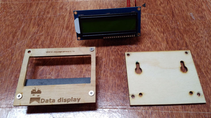
Hardware assembly
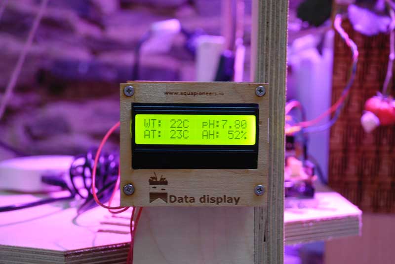
Let's have a look in live !
The output of that sketch is the video that you can see below.
Download
You access and download all the files generated during this week from my google drive:
- Libraries
- Adafruit_LiquidCrystal library.
- OneWire library
- DallasTemperature library
- DHT library
- Code
- “I2C Scanner” sketch
- I2C + DS1820 Arduino sketch
- I2C + DHT22 Arduino sketch
- I2C + pH Arduino sketch
- Main program for I2C + DS1820 + DHT22 + pH Arduino sketch