Final Project
Development
At this stage of the end of the fabacademy, I wasn't able to proof the concept of this pump. I need more time to investigate the feasability and design a making process that's simple enough for anybody to do it.
Though, I will explain on this page all the work I did so far.
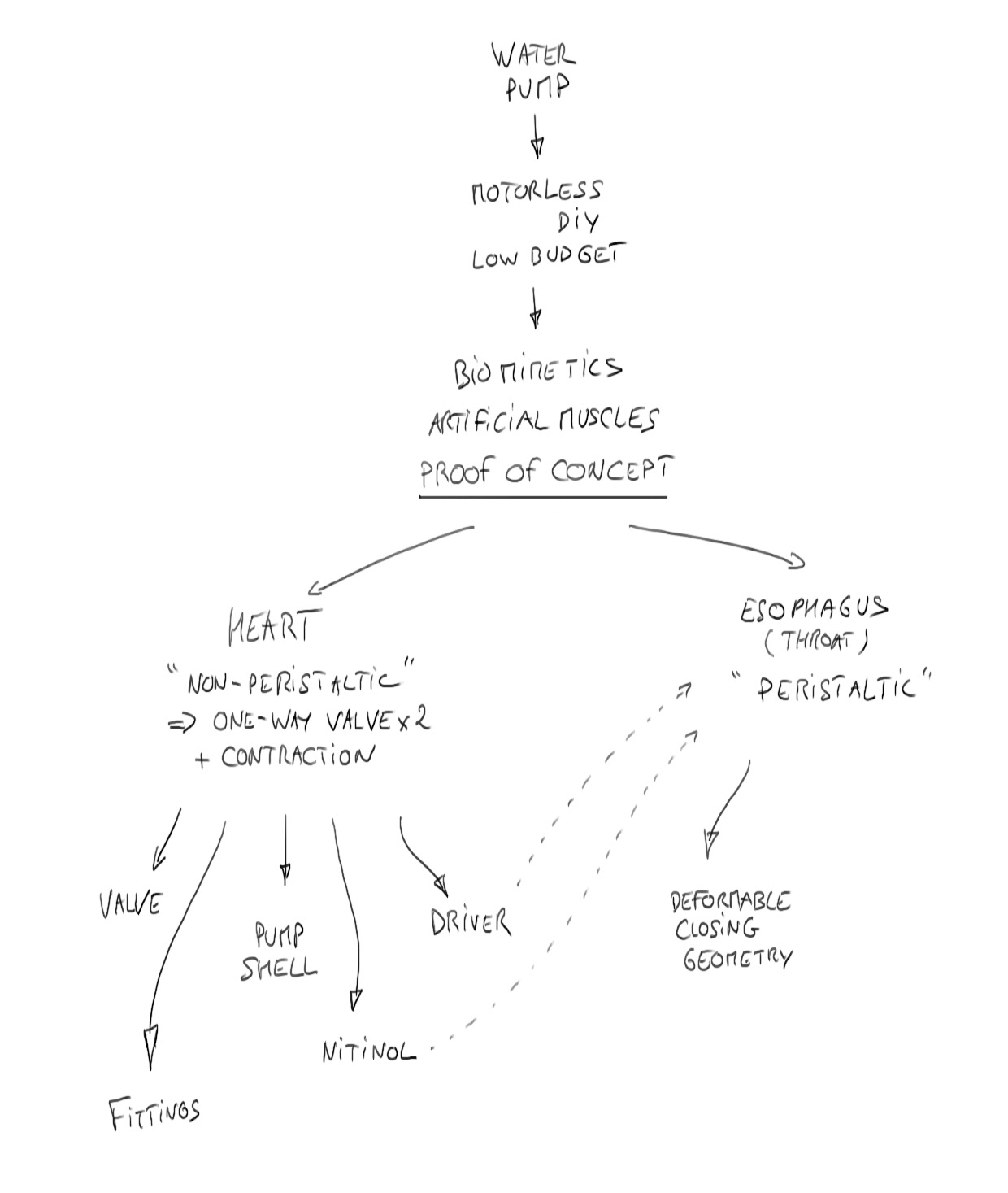
Here is the global development process I have in mind :
I see two main categories : "Heart" type and "Esophagus" type.
I will start to focus on the Heart type as I think it could be an interesting step towards the peristaltic type.
General Process
As shown above, I see my project having 5 different axis of development :
The 5 sub-projects
Hence, this Table Of Content :
The many parts produced along the way :
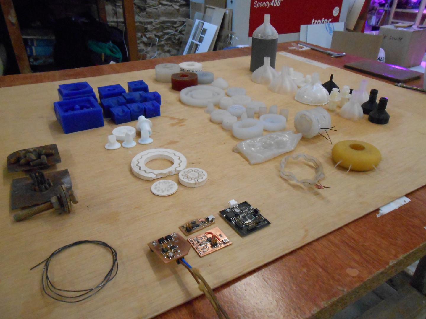
Some of the parts produced during the development
Here is the set up that I will use to evaluate how my system works :
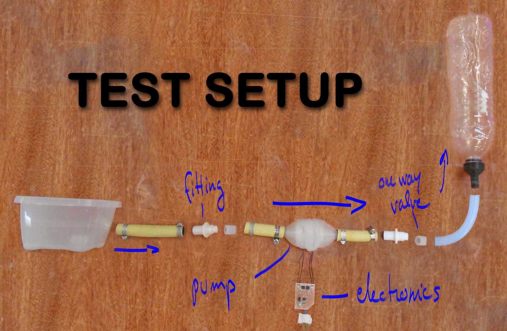
Evaluation set up
Rubber Shell
Here is the process of development for the Pump's shell :
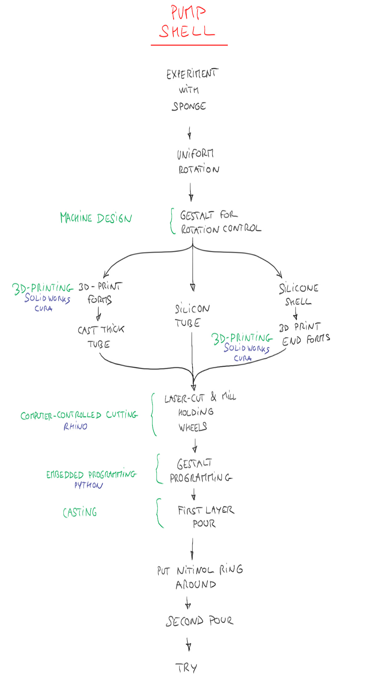
Pump Shell structure development process
the goal here is to experiment and prototype with shapes and materials for the pump shell that will embody the Nitinol.
I first want to have a "feel" of the different hardness of the rubbers and silicon that we have in the lab, so I make some basic test in the shape of a tube with different "shores" (basic parameter for rubber hardness) using pipes pieces for forming :
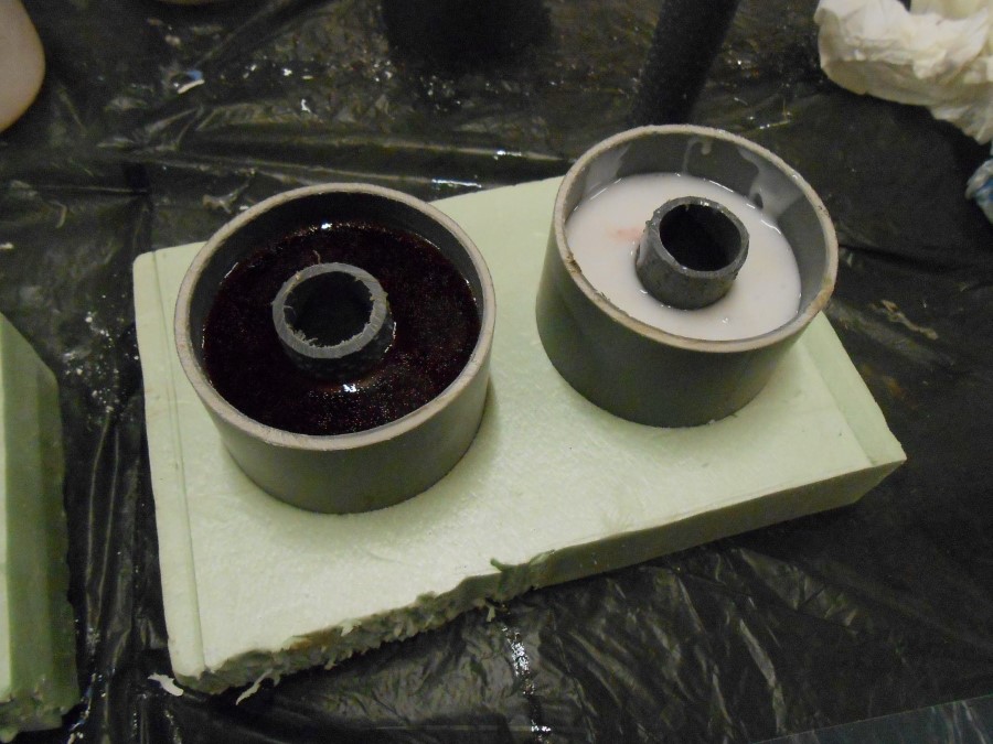
rubber casting tests
Different casts, gradient of hardness from left to right :
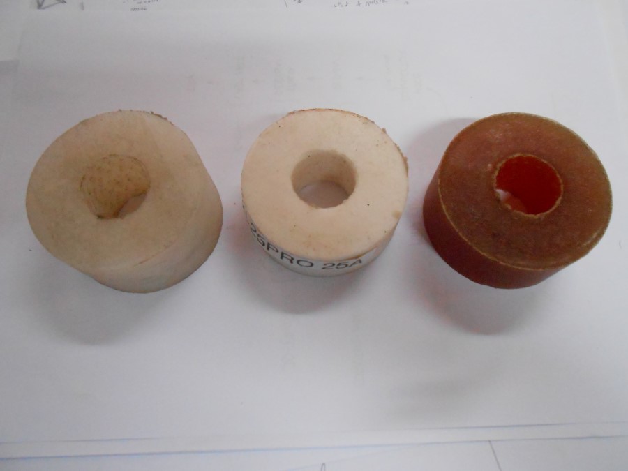
Here, Ecoflex OO50, formsil25 pro and PMC 121/30
Now that I get a better feel of the different kinds of rubber available in the lab, I choose the EcoFlex OO50, to me it matches the softness and solidity I'm looking for. It also cures in 4 hours, better than most of the others (16 hours)
I first try a method that involves 3D printing the forms to cast a slim silicon tube :
I print 2 parts and laser cut a cap :
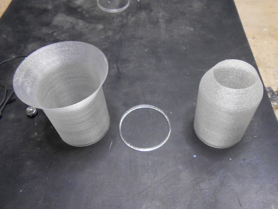
3d printed forms with the laser cut cap bottom
I place the cap at the bottom of the inside form :
assembling
Here is the form ready for pouring the rubber :
assembly ready for pouring
I pour the formsil25 (running many things in parallel, this happen to be poured before the choice of using ecoflex 0050.
pouring the silicone
Here is the result without the outside form :
Shell with outter form removed
I decide to abandon this way of making the shell because it's difficult to embbed the nitinol wire. It would imply having sealed holes in the forms to let the Nitinol out.
I decide to try pouring the silicon on a rotating form instead.
I first try on a sponge fixed on a drill. I have the idea that sealing the outside of the sponge could be a way to create a "heart"-type pump with check valves.
Using a drill to uniformly coat and seal the sponge with silicone
Interesting result after curing, I'm sure it could be useful for something :

Unexpected but interesting result, centrifugal force too high
The sealing works. But I clearly need to have a better control on the rotation.
Plus, before I go ahead and pour a second layer with the nitinol wires in between I want first to run many tests of Nitinol contracting rings of rubber.
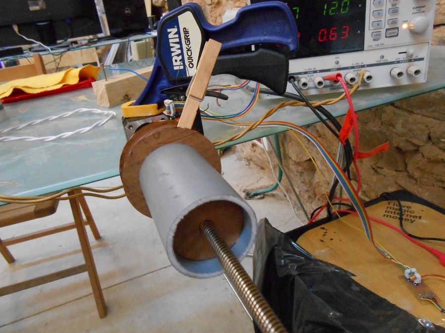
I then decide to pour not on a sponge (to save the amount of sponges I would use) but on a cylinder form, using a gestal node with its stepper motor for rotation :
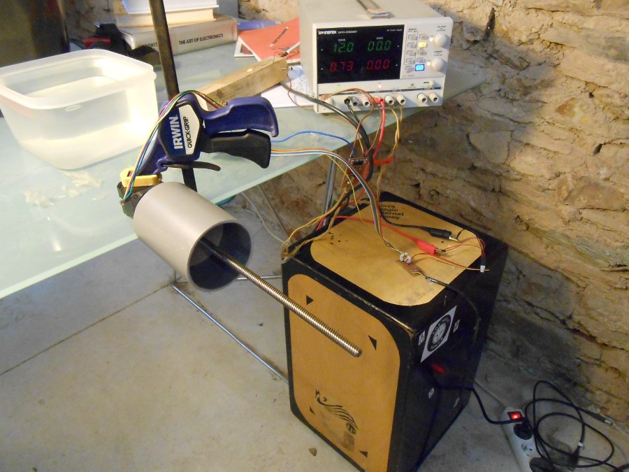
Gestalt set up for coating cylindrical shapes
Here, the part of the python program that runs the stepper motor forever at a chosen rotation speed :
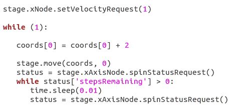
Part of the Python program
I laser cut cardboard holders for inside and outside :
using carboard hub
I use this method to produce several nitinol rings for testing.
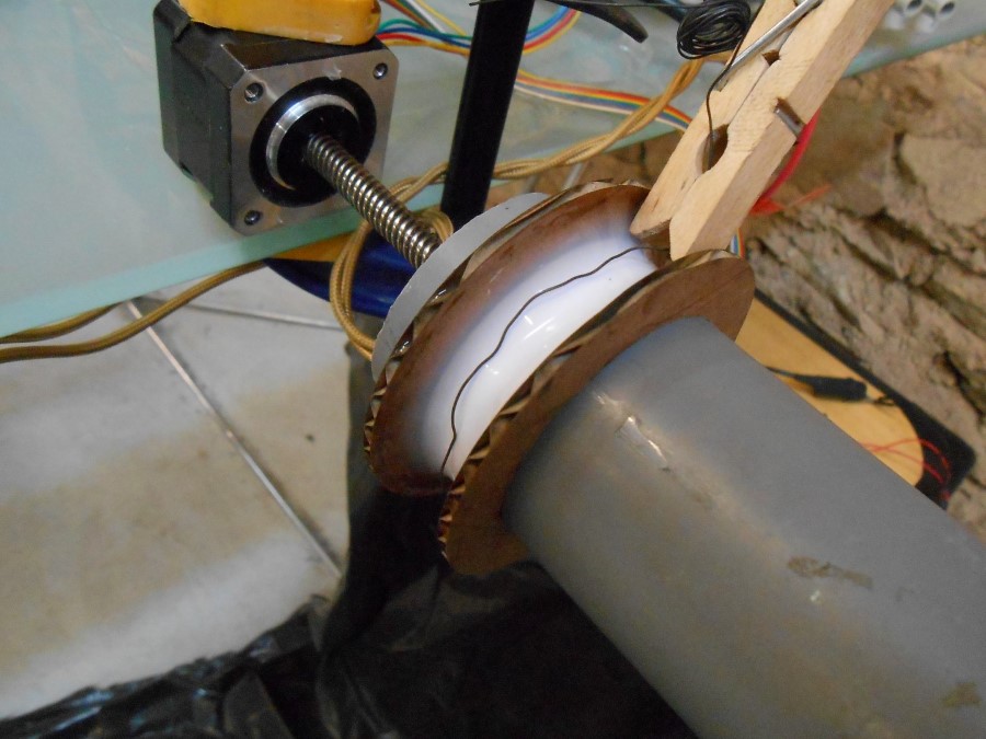
Nitinol wire on top of first silicone coating
Here, the second layer poured that embeds the Nitinol wire :
Nitinol wire sandwiched in between two layers of silicone
To make quickly several rings of Nitinol, I separate them with tape and pour at once :
creating several rings
Then, in parallel, I try a way of creating the pump sides.
My idea is to have the check valves directly in the ends, so I need some sort of a reducer on each side.
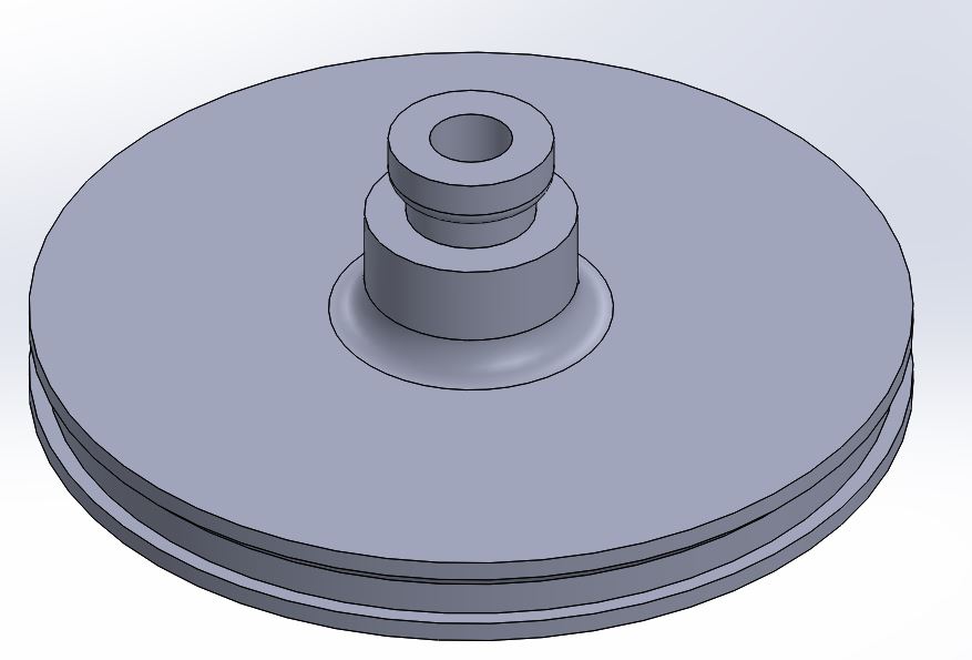
I design one in Solidworks :
section view of the shell end reducer
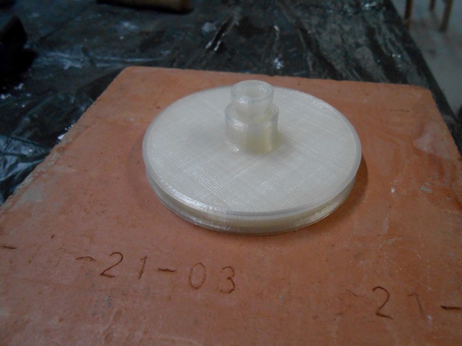
And 3d print it :
printing the end reducer
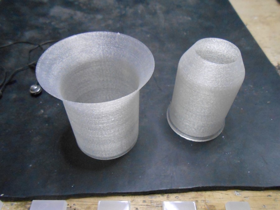
I used the "spiral" function in Cura to print quickly only the shell. I'm happy with the result :
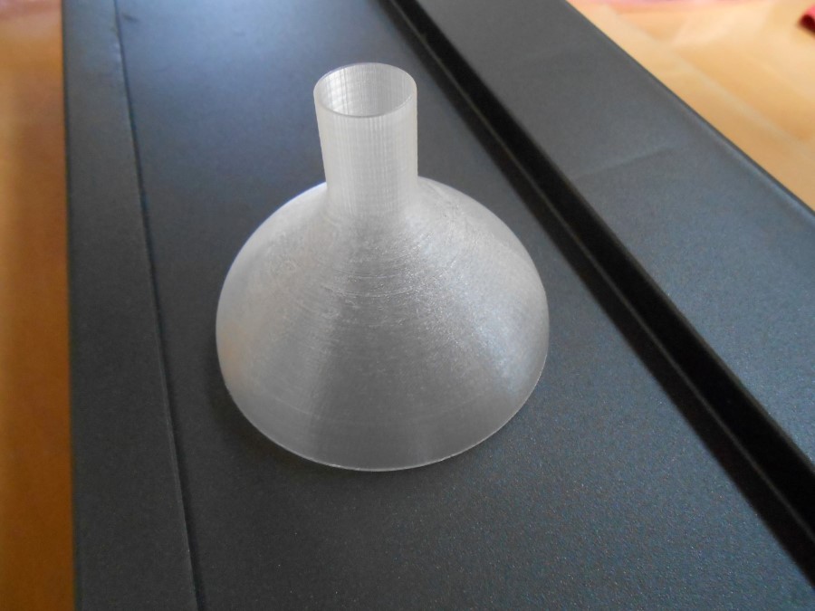
The end reducer form printed with spiral option
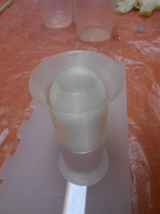
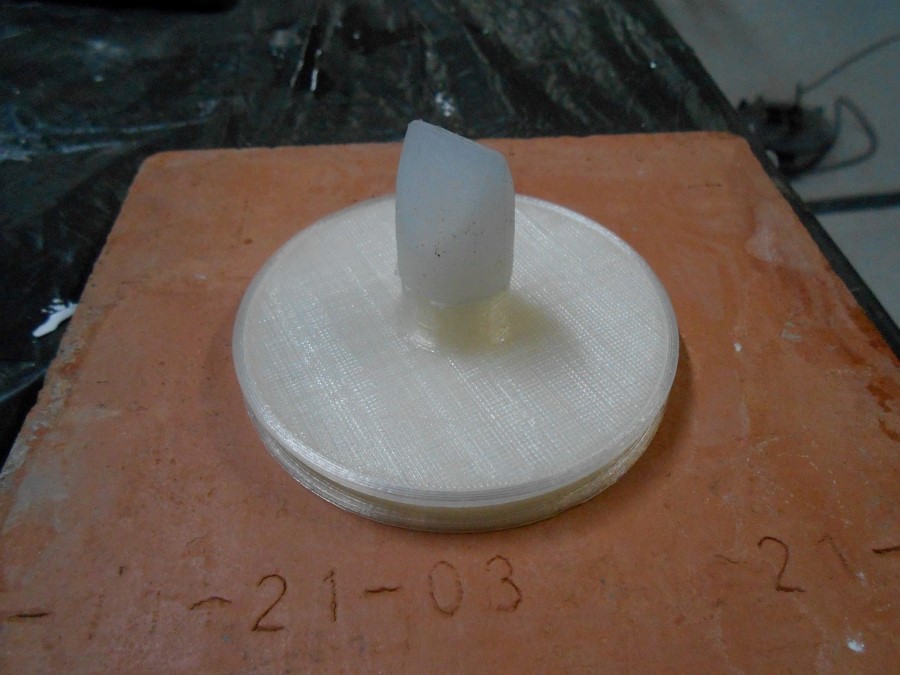
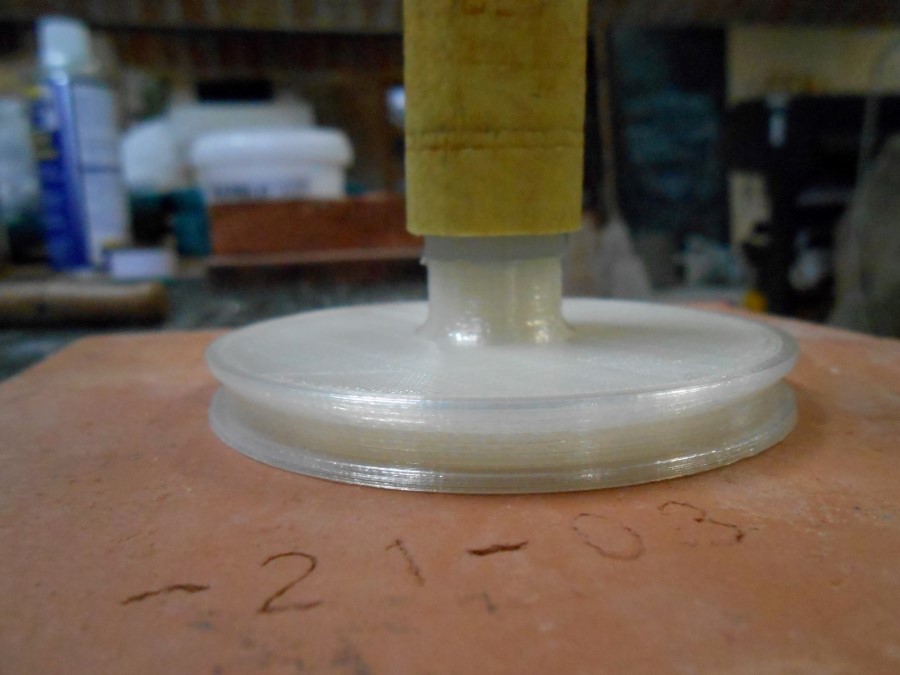
Here is my pump form ready to be coated with Silicon :
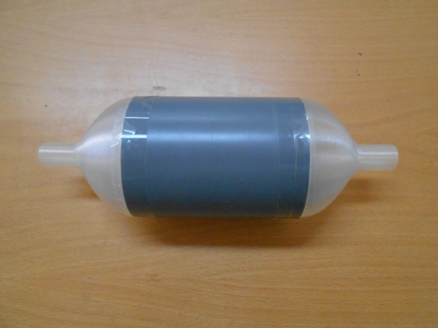
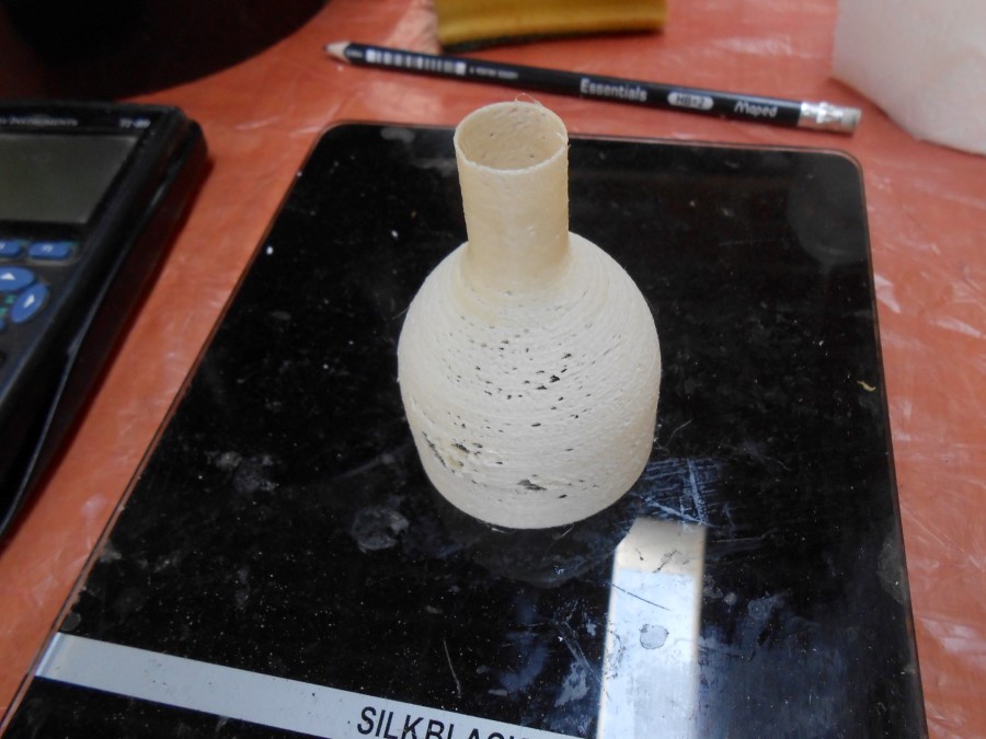
The complete shell
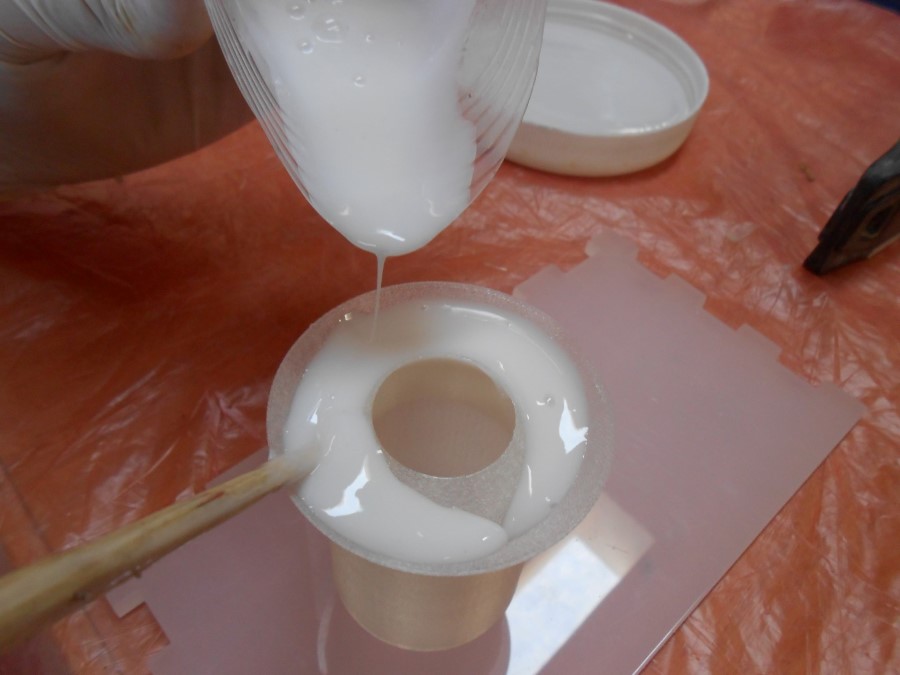
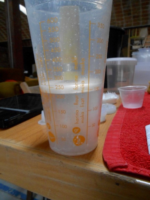
I make a coating test without Nitinol because I just want to check if the Silicone is enough stretchable to take the form out after curing.
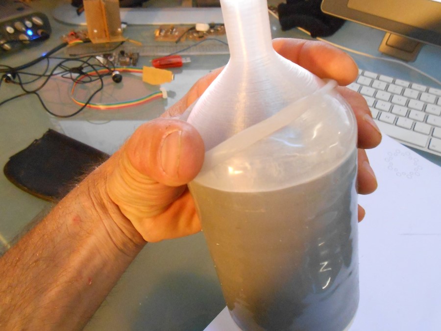
taking the form out of the first coating
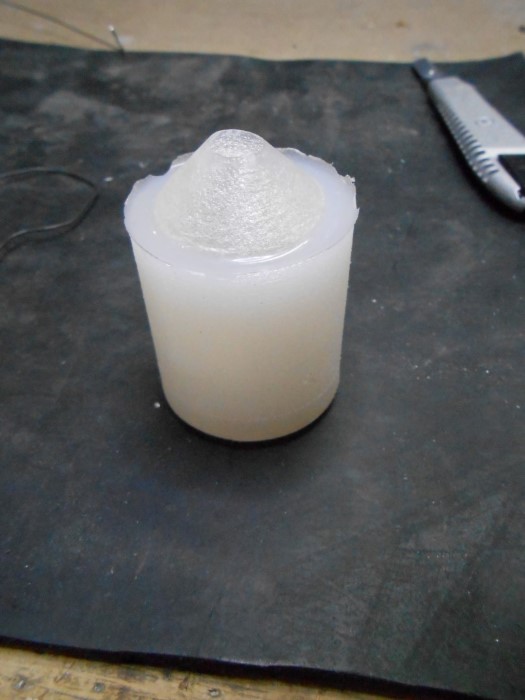
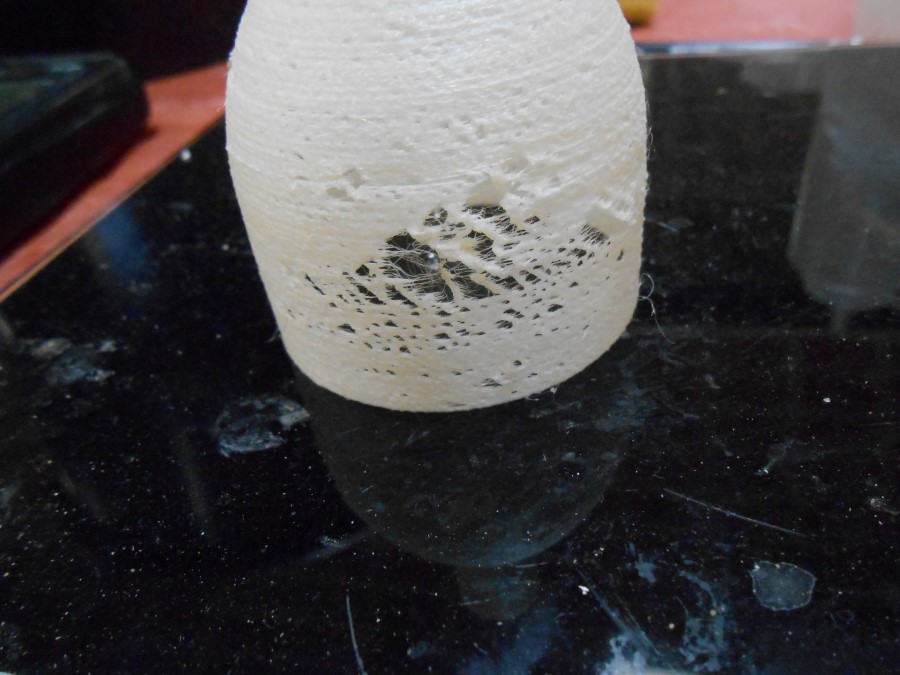
Unfortunately, it broke :
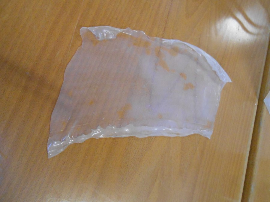
Broken coating = sheet of Silicone
We have some filament in the lab that dissolves in water, so I had the idea to make a dissovable form :
Dissolvable 3d print
But I wasn't able to tame this filament and it was starting to use up too much time..
Unwanted holes in the print
Here a video of different stages of these experiments :
Compilation of shell making processes
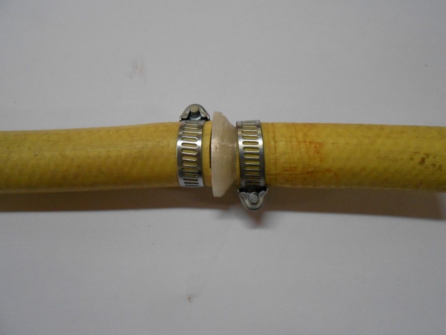
I decided then to take an intermediate step in the general process and have just a deformable cylinder closed by plastic parts with grooves where tie wraps pressure seals the system :
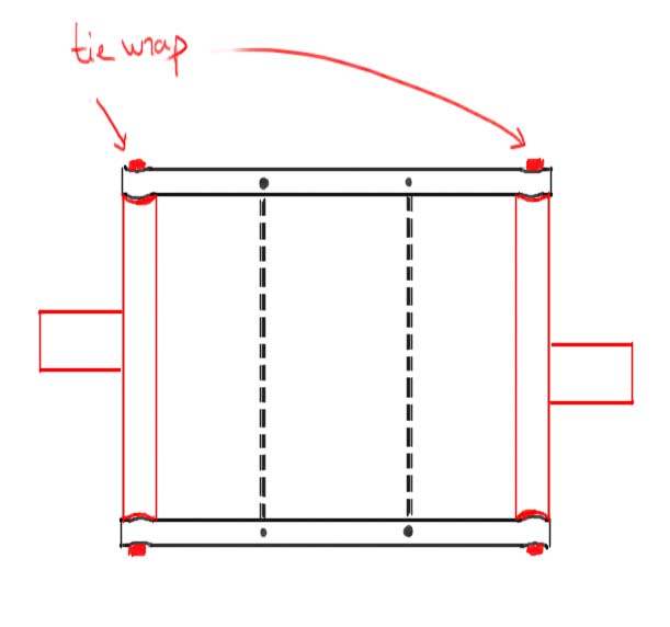
Simpler design to start with
Souce Files
Here are the sources files of the projects I talked about in this section :
Pump end reducer to 3d print for Solidworks
Valves
Here is the process of development for the Valves :
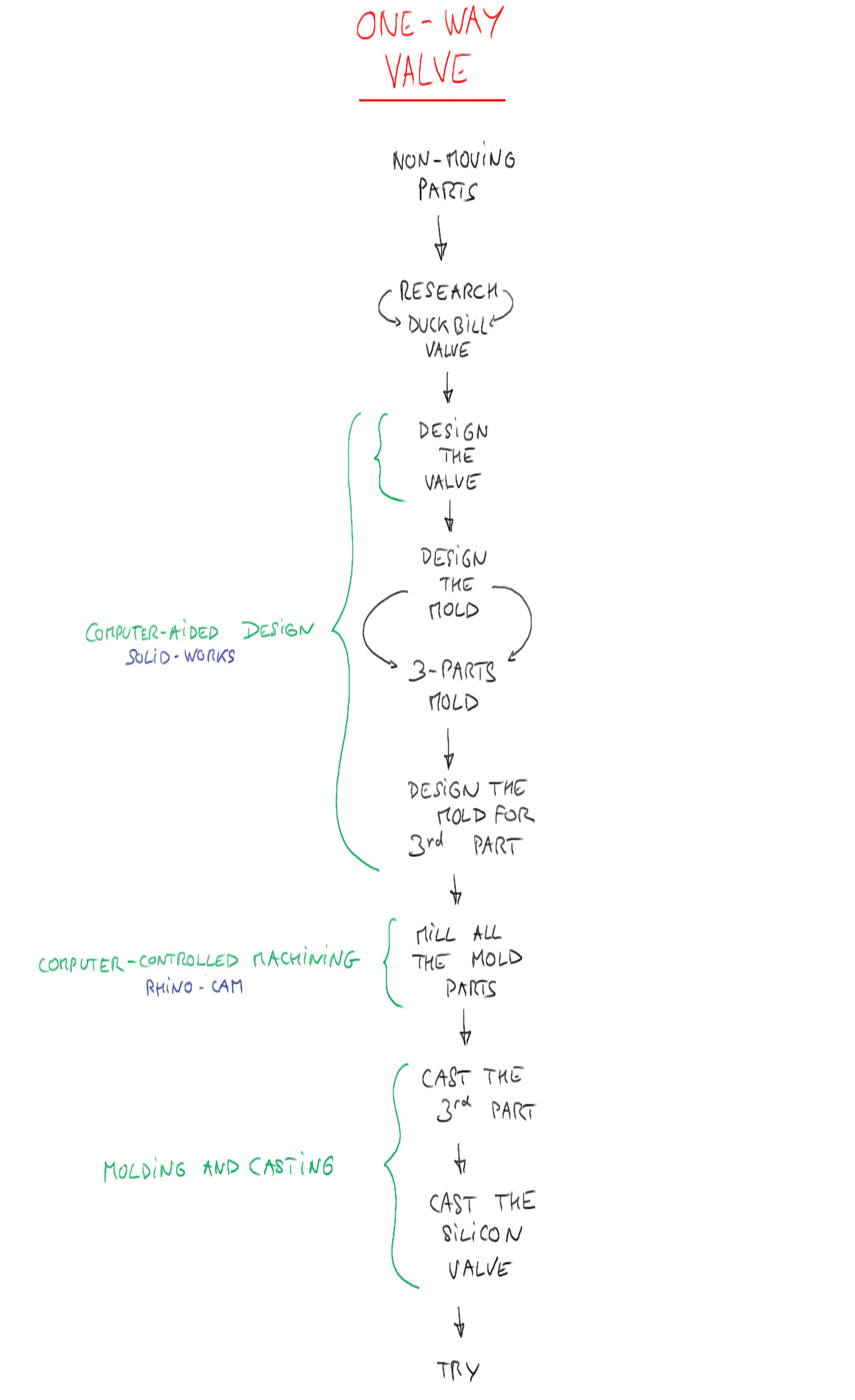
Valve development process
The idea here is to do duck-bill valves, which are one-way or check valves. they look like this commercially :
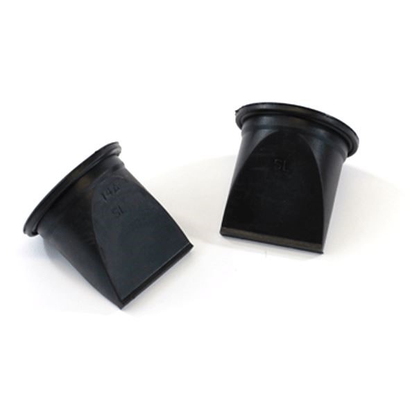
Commercial duckbill valve
Here is how it works :
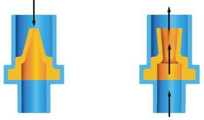
working of a duckbill valve
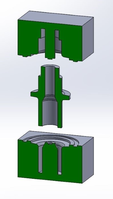
I design a three part mold :
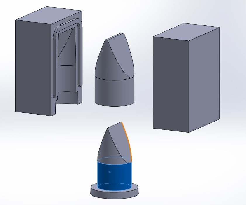
3 parts mold
I design a two part mold for the third part (the inside) of the previous molding strategy :
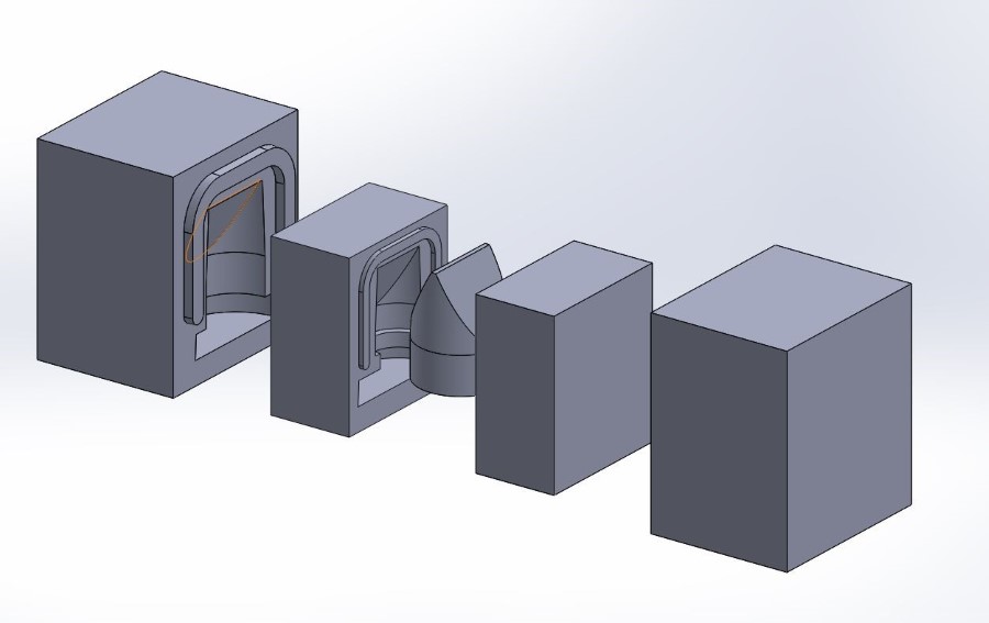
in the middle - the 2 parts mold for the third part
I mill the mold in wax :
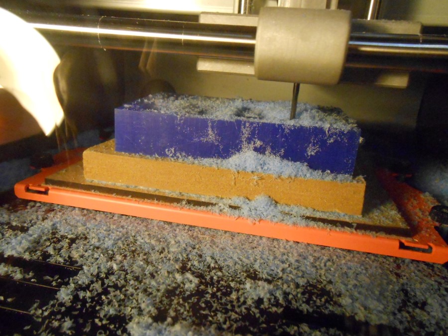
Milling with SRM-20
I'm running out of wax, so I start recycling by melting the wax chips :
I first use a pot.
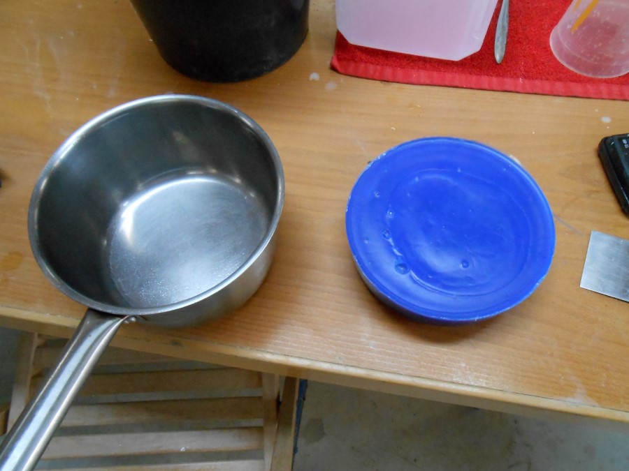
Remelting the wax chip
But that's not really efficient because I'm milling cubes in a big cylinder
I then decide to make a mold for wax recycling.
I first design and laser cut acrylic to make two box forms
It always starts by finding the right kerf by doing small fitting tests :

Joint tests
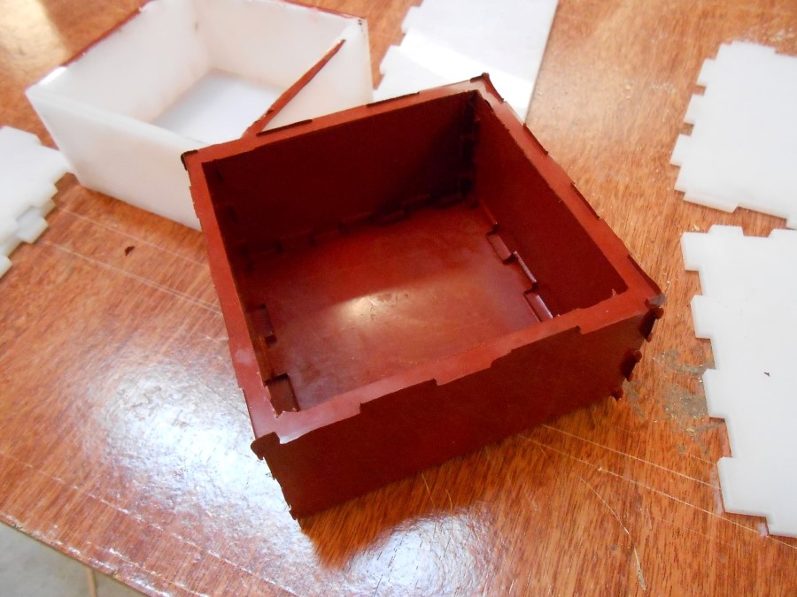
I then asemble the boxes
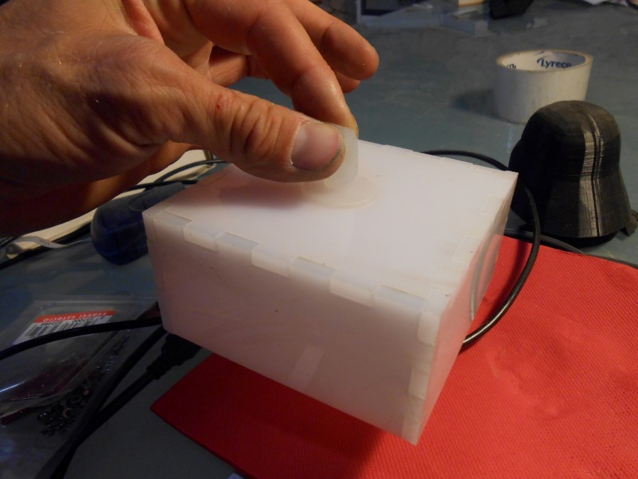
Box assembled
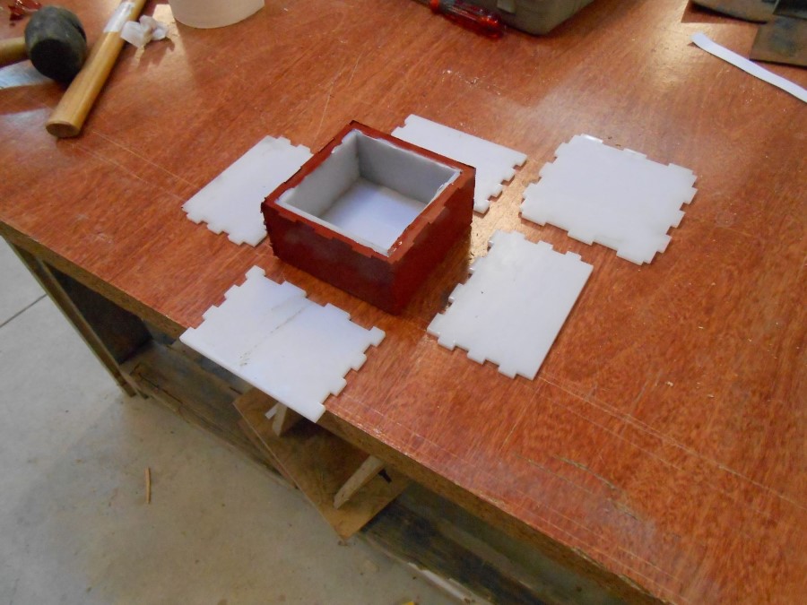
And place the little one in the big one :
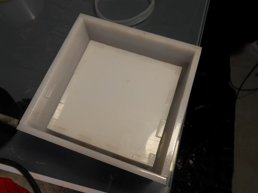
cubic forms ready for pouring the Moldmax silicone mold
I pour Mold Max 60 (Silicon that resist higher heats than wax melting ones) :
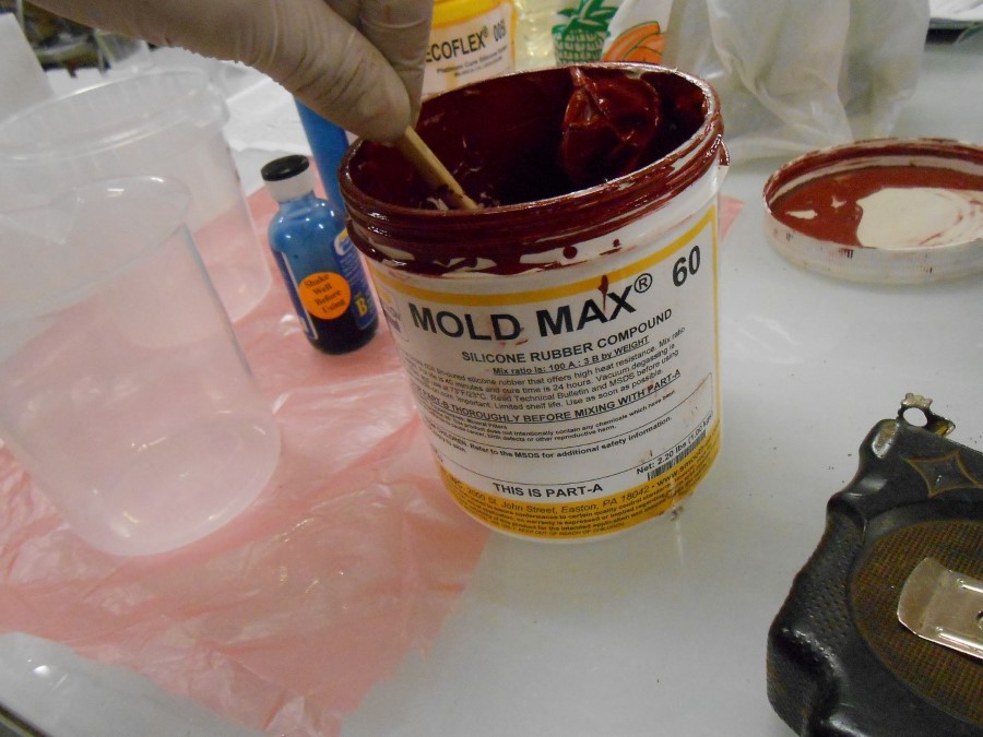
Moldmax60 comes from company smooth-on
And I get a nice mold :
unmolding the silicone mold after 16 hours curing
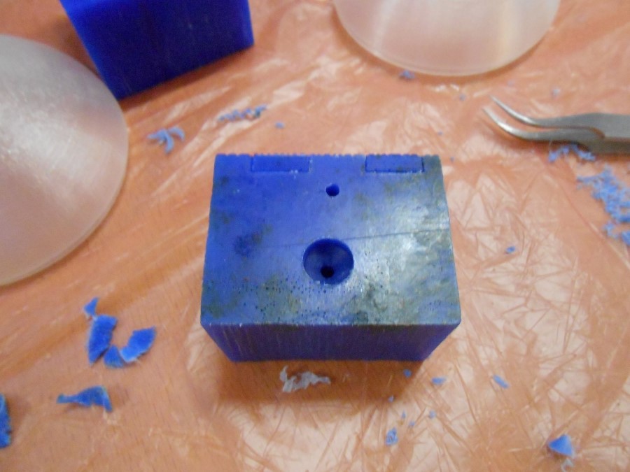
There is some very thin tongues due to the joints but it doesn't matter since the milling mainly occurs in the middle of the wax bloc :
Our wax chip recycling mold
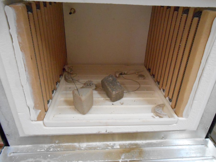
I can then melt wax chips in the oven :
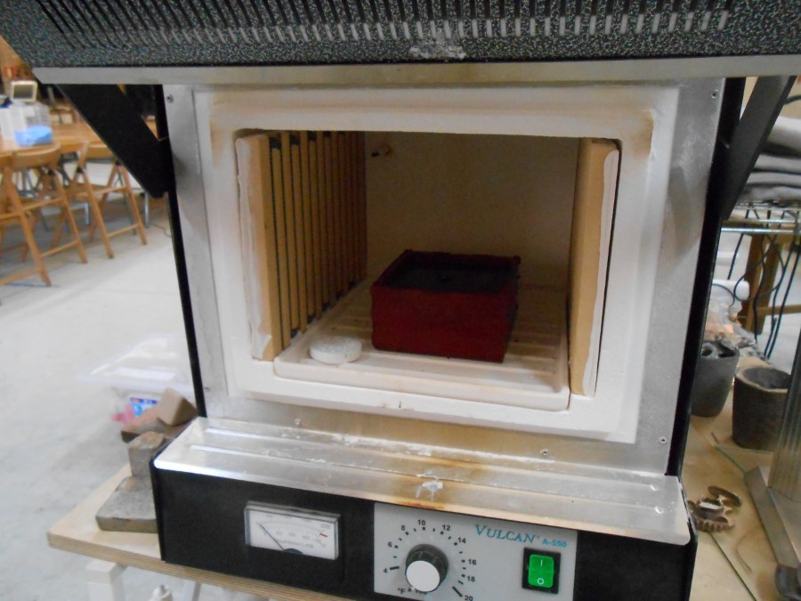
Oven at 200°C
And recycle wax blocs :
wax block after melting
Then I surface them :
Surfacing the wax block
And mill my molds :
Wax molds for the valve
Here I cast the internal negative of the valve :
liquid plastic poured in wax
Here it is after curing :
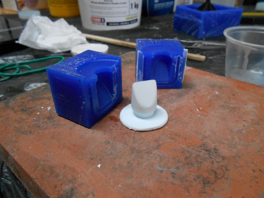
The internat valve negative just cast
Then I assemble the valve three part mold and cast the silicon.
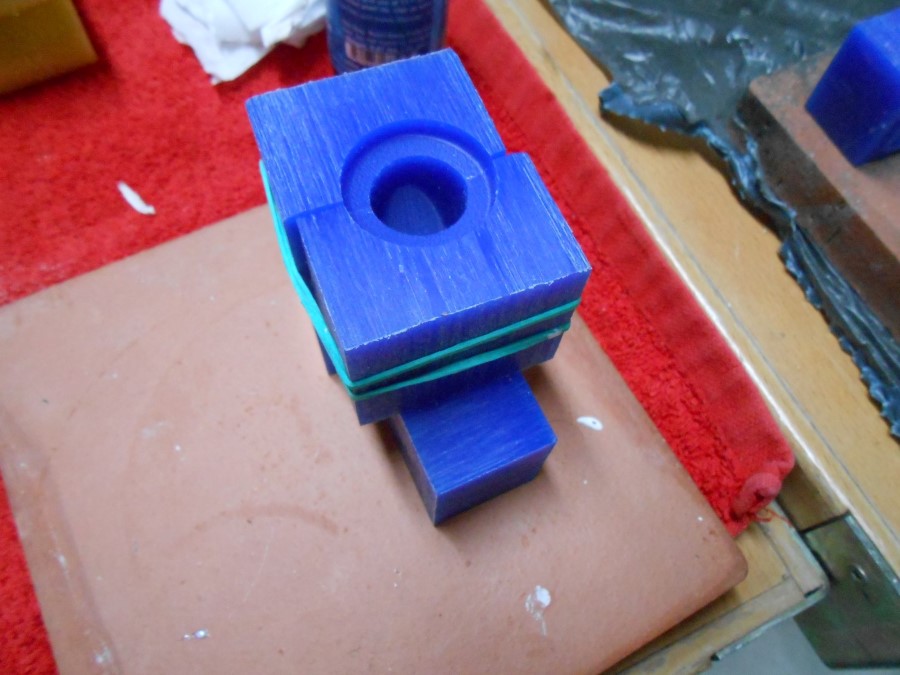
wax mold for the valve
Pour the silicon :
pouring the ecoflex 0050
And place the third part (internal negative)
Placing the third part - the internal valve negative
I let it cure for 4 hours...
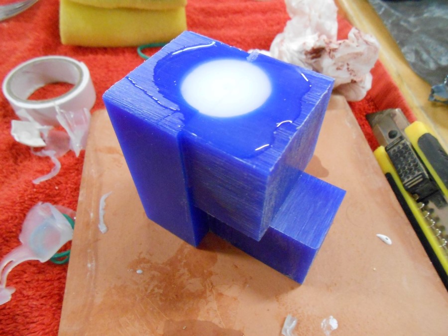
Valve curing
And demold :
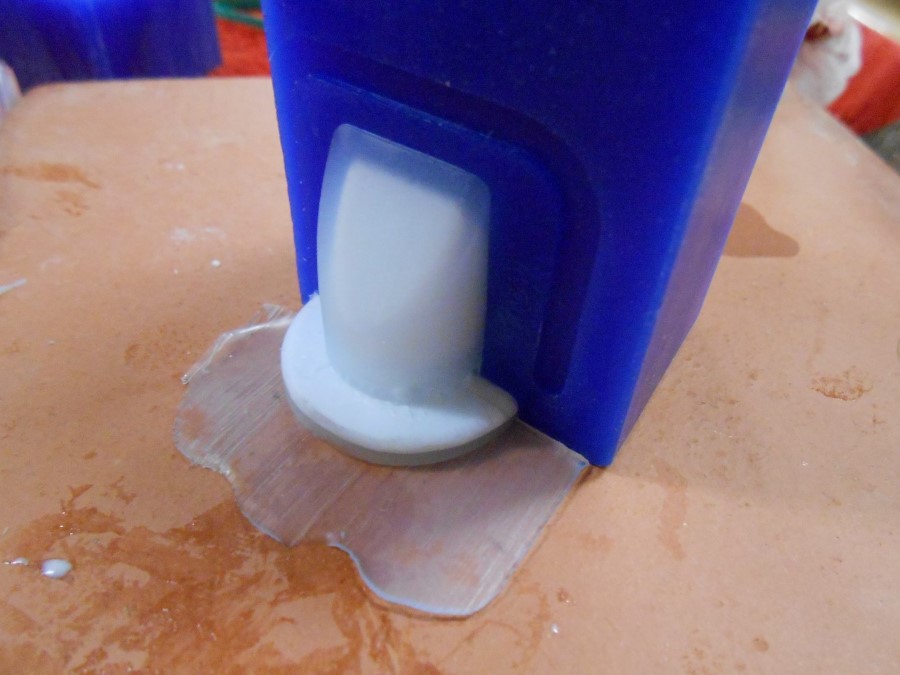
see through valve shows the internal part
And here is the Valve :
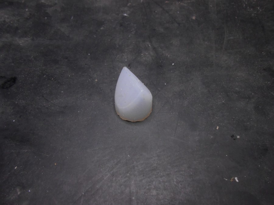
only the valve
I just need to slice cut the top with a very sharp knife :
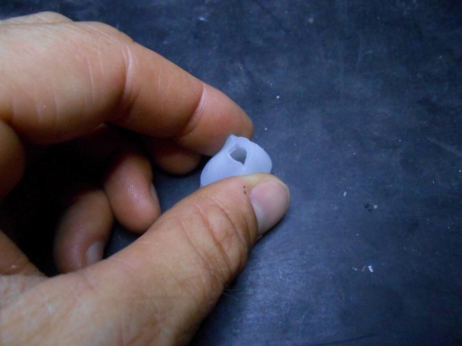
Valve in opened position
Family picture of all the mold parts :
All the components to make the valve
Souce Files
Here are the sources files of the projects I talked about in this section :
Valve CAD files for Solidworks
Kerf test for Rhino/grasshopper
Box for Mold Max Silicon Mold CAD files for Solidworks
Fittings
Here is the process of development for the fittings :
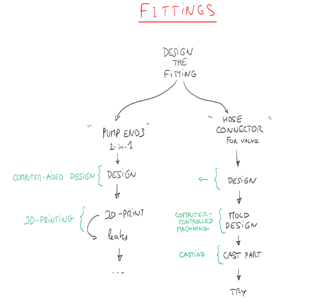
Fittings development process
I start designing the parts in Solidwork :
CAD design of the shell cap end
Then I 3d print them :
3D printed shell end cap
I put the duckbill valve I designed and made on it :
Valve on end cap
I insert it in a hose pipe :
insertion in the hose
I use a collar to tighten it and I run a test. The hose pipe is filled with water : Absolutely no water goes through the Valve, nice!
Test for checking water leakage
I also want, for conveniency, to have a simple hose-to-hose on way connector (with the valve), so I design it :
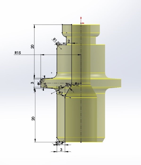
CAD design of the one-way connector
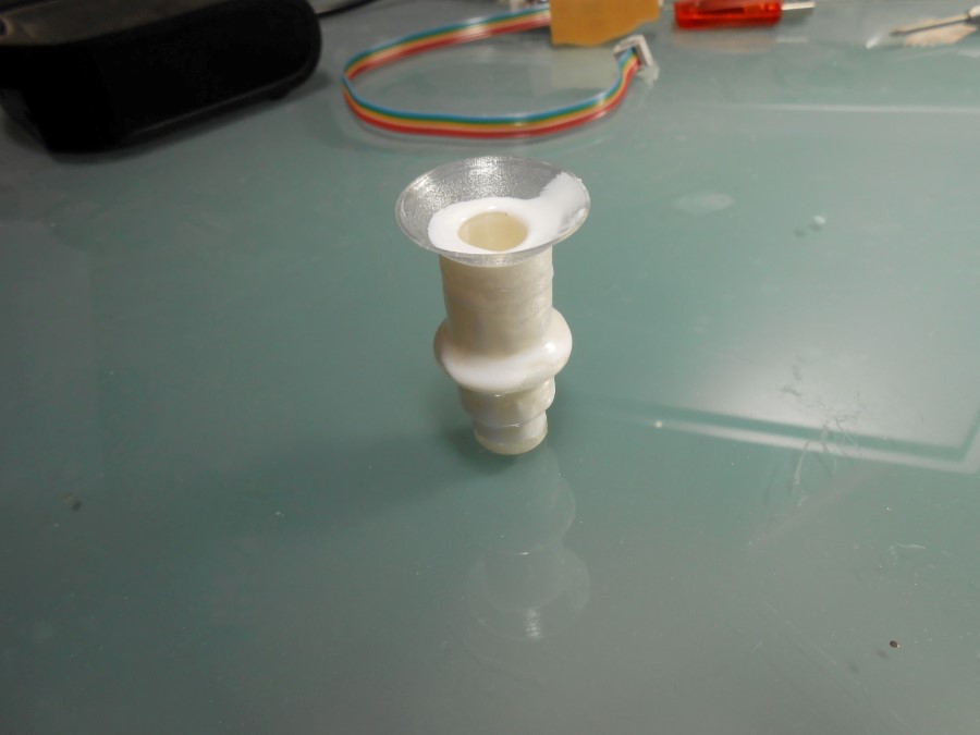
And 3d print it :
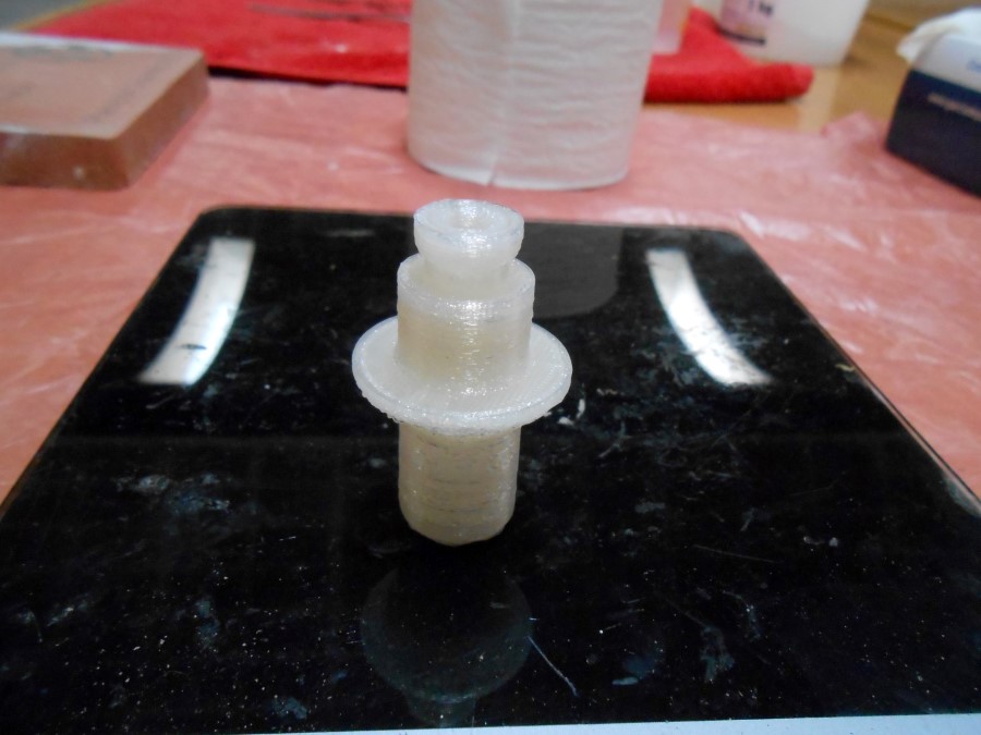
3D printed connector
I put the valve on :
Valve on connector
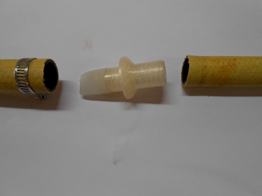
Then I thighten it :
Everything together
The 3d print leaks a lot. I decide to cast this connector
I try casting in between 3D printed parts :
Casting liquid plastic in 3D printed forms
Does not work since it's impossible to take the form away after.
I design then a mold for casting in wax :
2 parts mold for the connector
I pour liquid plastic using a vent :
Vent and funnel
And here we go we have it :
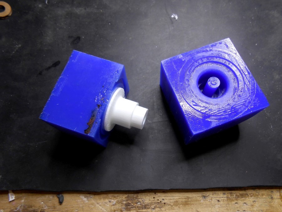
Demolding
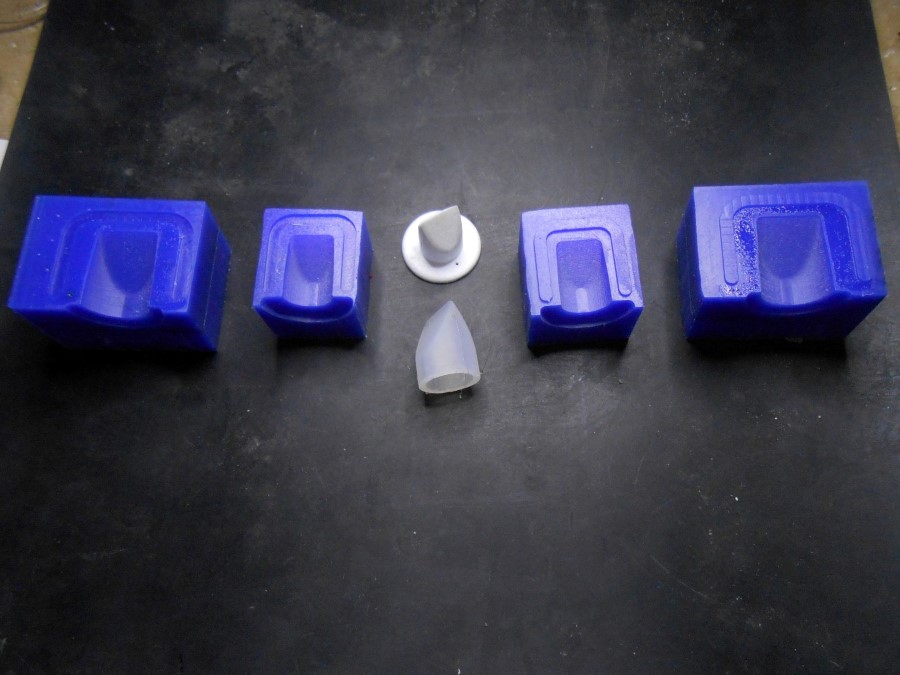
The components :
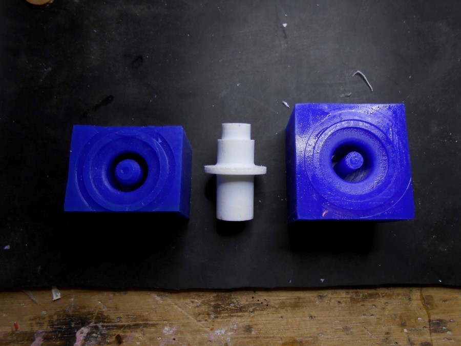
2 parts wax mold and its cast part in the middle
I then do the same as earlier, I put the valve :
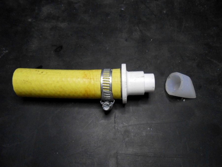
Connector - exploded view
And try the one way connector :
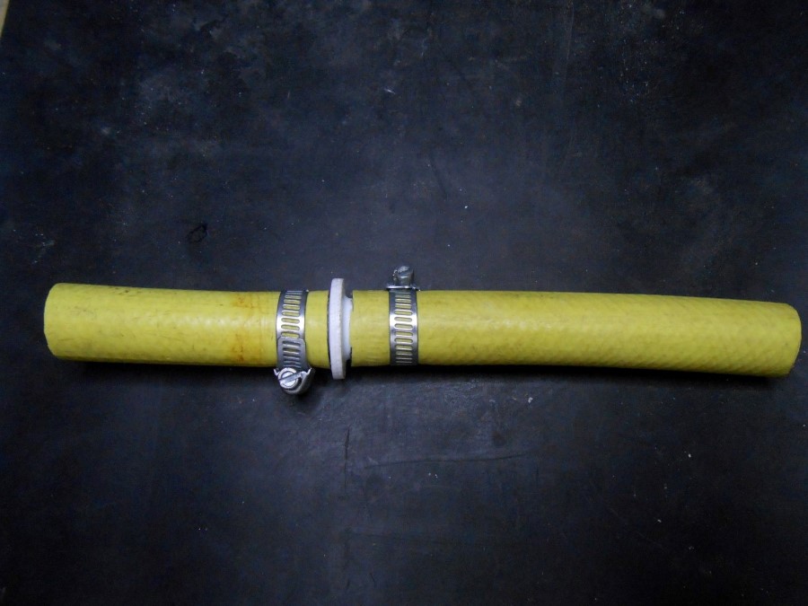
Connector tight
In this video I first inhale and you can hear the bubbling, air goes through up the valve and water inside the upper hose. Then I make pressure to try to push water down... impossible
trying the valve with lung pressure
Souce Files
Here are the sources files of the projects I talked about in this section :
One way connector CAD files for Solidworks
Flat pump end connector CAD files for Solidworks
Nitinol Rings
Again, Here is how Nitinol works and what my strategy is for contraction :
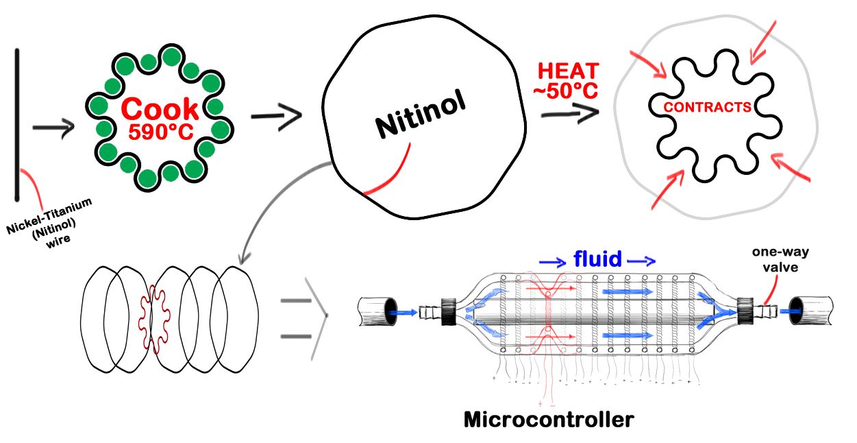
Nitinol pump principle
And here is the process of development for the nitinol rings :
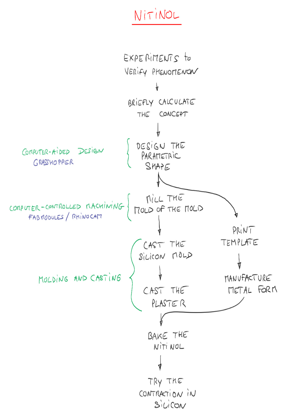
Nitinol ring development process
In order to anneal (590°C) the Nitinol into the contracted state, I need to design a form that will hold it in the Oven.
It then needs to be a material that can withstand high temperatures.
I plan to cast it with plaster.
In order to cast the plaster holder I need to do a mold based on a parametric design that mimics the contraction of the wire.
I use Grasshopper for this :
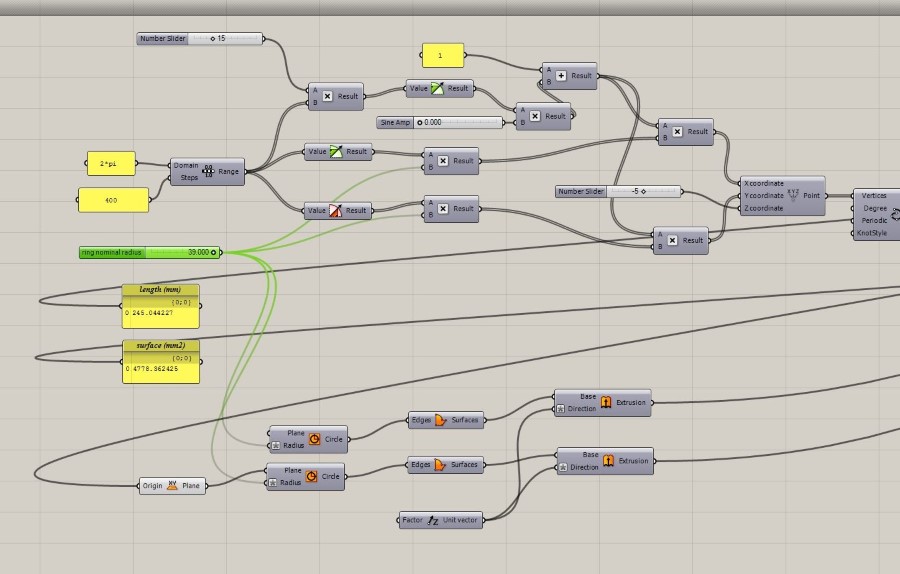
Grasshopper algorithm
Here the complete algorithm :
The whole grasshopper definition
In green here, the Nitinol wire :
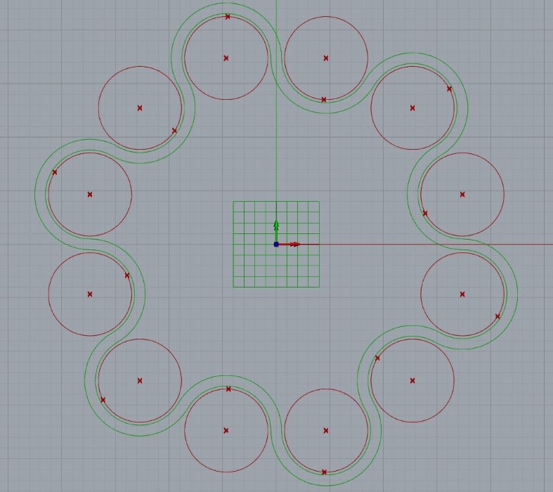
Simulation of the Nitinol wire contraction
I "bake" the grasshopper geometry (negative) and make a positive mold out of it :
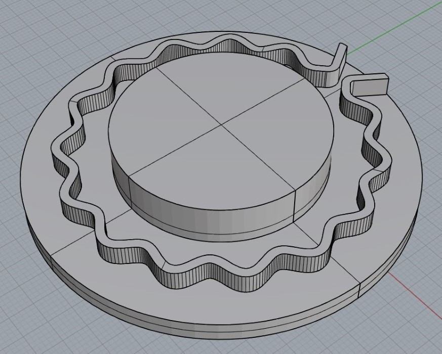
negative of the Nitinol wire holder
I use fabmodules to calculate the toolpath :
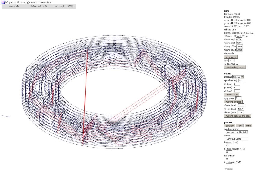
Calculating the toolpath in fabmodules
And here is the wax positive mold :
Max mold for casting negative silicone mold
I use Ecoflex 0050 to make the mold
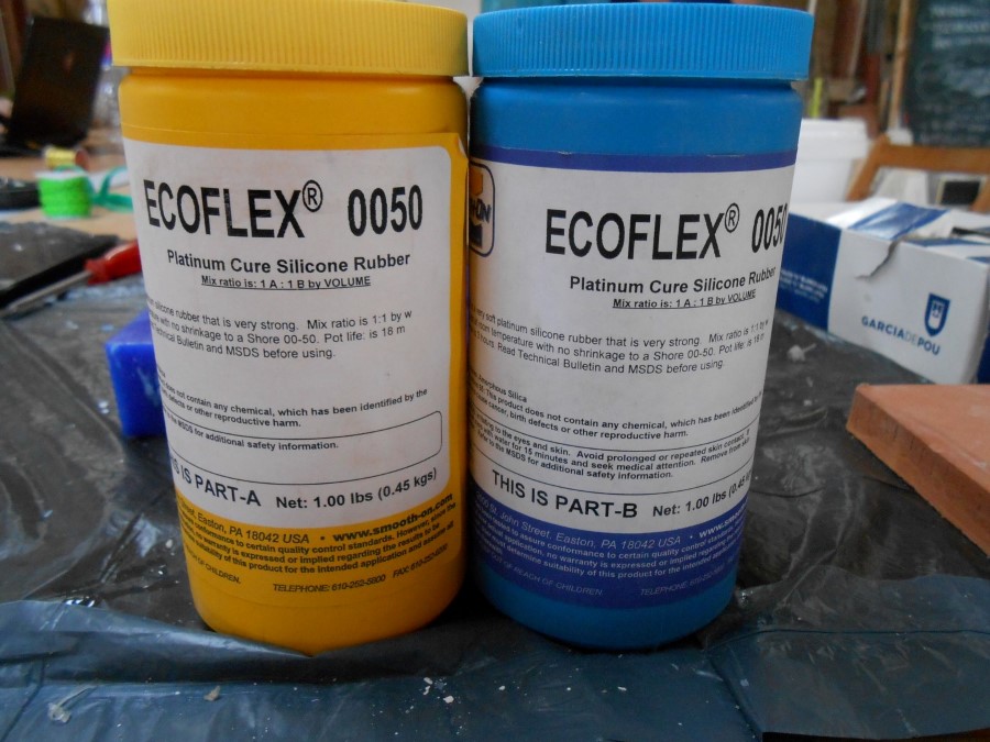
Silicon shore OO50 from smooth-On
I usually need a good degassing with Ecoflex :
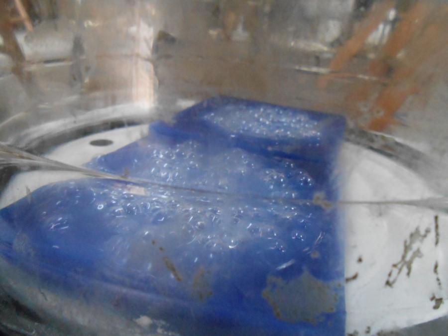
Degassing
For this I use a vaccum pump that wi have in the lab :
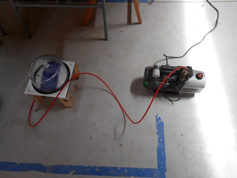
Our vacuum pump
Nice bubbling that indicates that air that was trapped is going out :
Air bubbling out of silicon when low pressure around
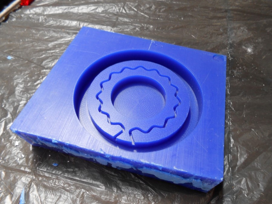
And after curing I get :
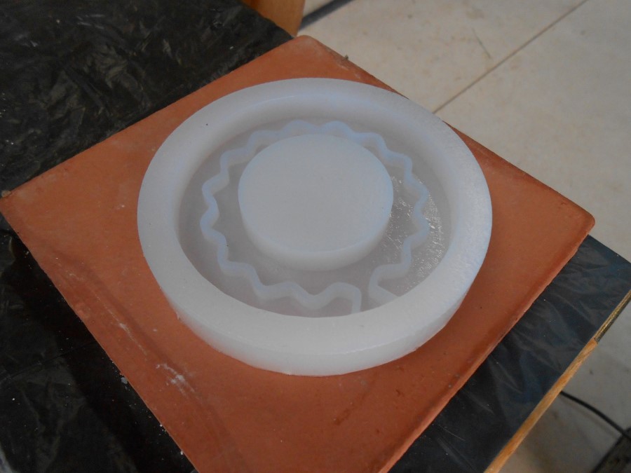
The silicone mold for plaster cast
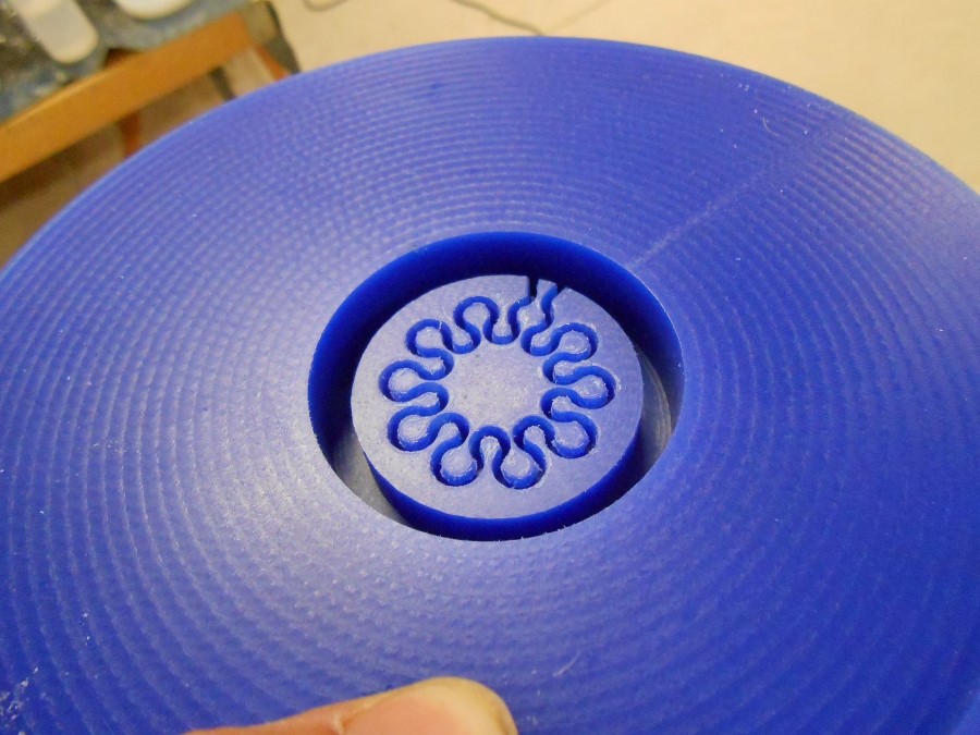
Now I cast with plaster (marblecast) and I obtain my annealing holder for the oven.
you can see in the following picture the Nitinol Wire inside of the channel :
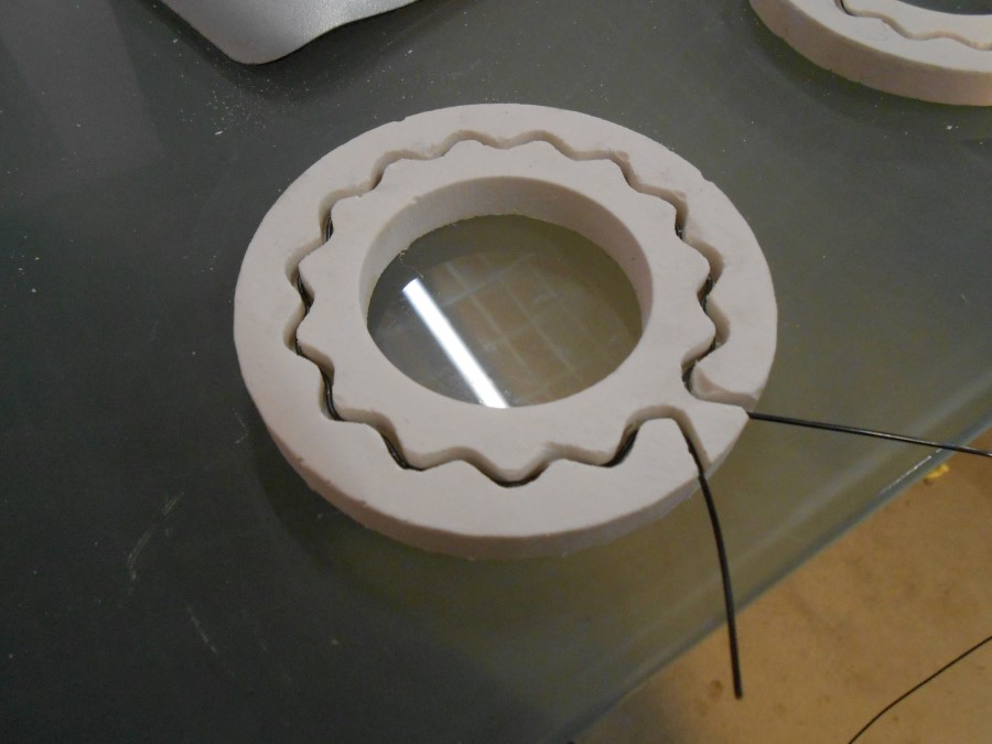
Nitinol wire inserted in the plaster holder
I make several shapes, taking benefit of the parametric design :
changing the wrinkliness with grasshopper
To be noticed that the length of the Nitinol wire remains always the same :
Here is another mold (postive) :
CNC milled wax mold
For silicon (negative) mold :
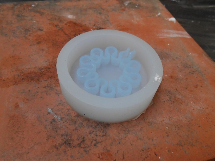
Silicone mold
Plaster casting :
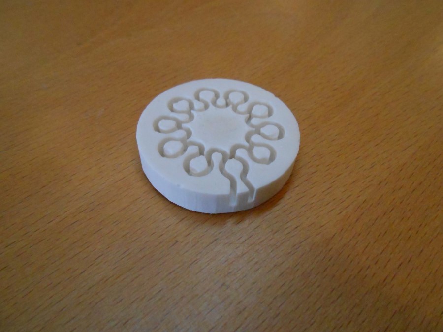
part cast in silicone mold
Same, Nitinol wire inside :
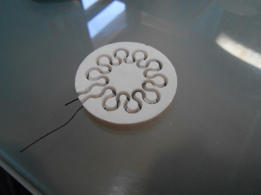
Nitinol wire inserted in the holder
Heating to 590°C in the oven :
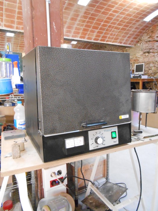
Our oven, annealing at 590°C
And we get our annealed shape :
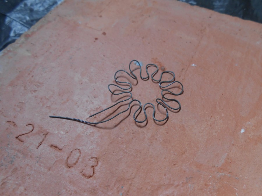
Nitinol wire just annealed in the contracted position
Let's try it in hot water :
Test of the nitinol's shape memory with hot water
I realized that I was quite lucky the first time. The plaster mold almost always cracks during annealing.
Exploded shape holder
I would have to do ceramics but I don't have the time.
Instead, I'll do a metal holder with screws in a metal plate.
For this, I use my parametric design :
finding the hole size and postions thanks to the grasshopper parametric design
...to print the position of the holes
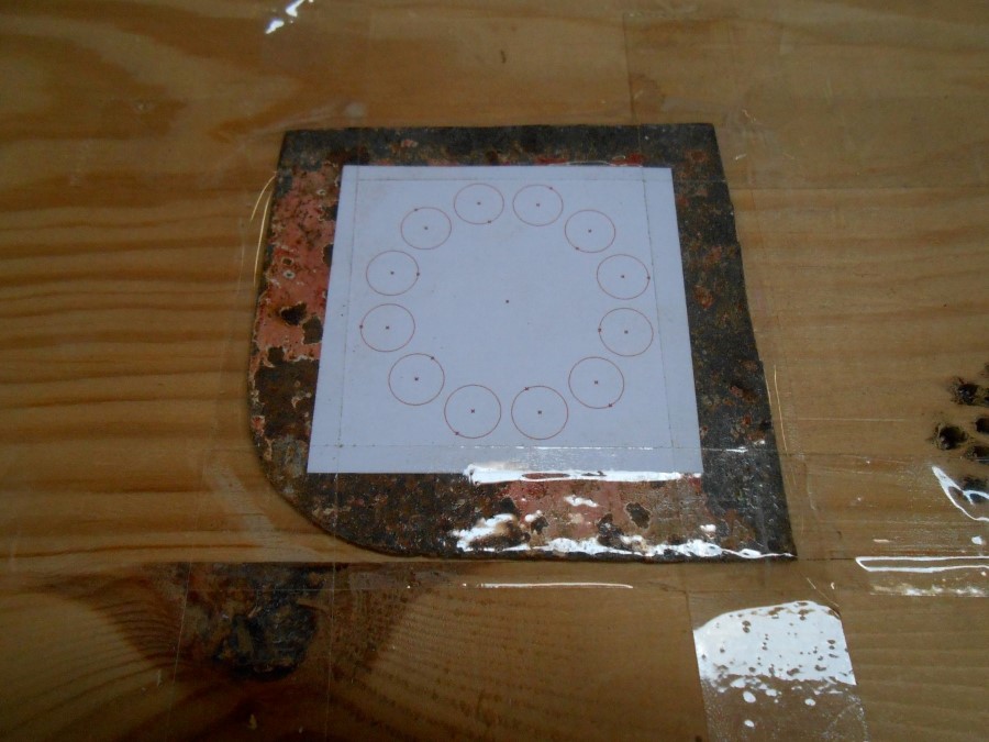
printed template on metal plate
I drill the holes :
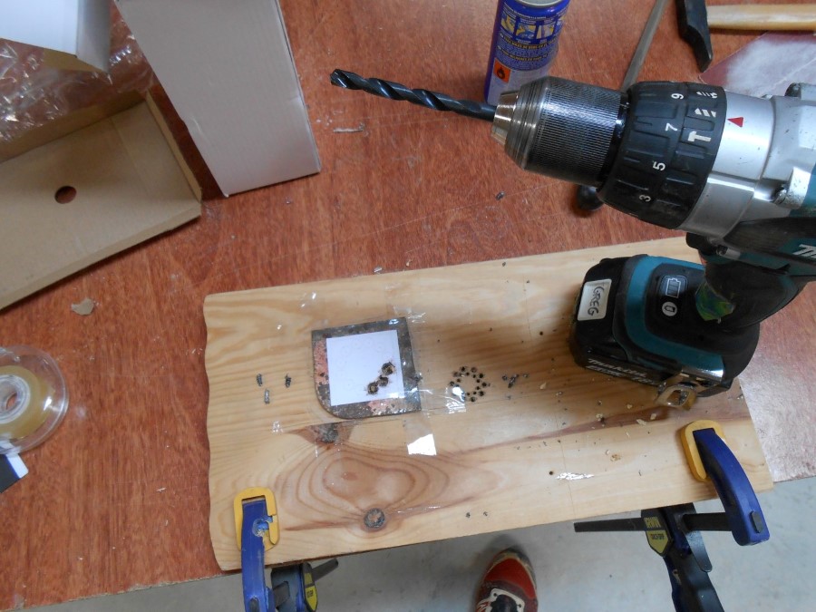
drilling the metal plate
... in the metal plate :
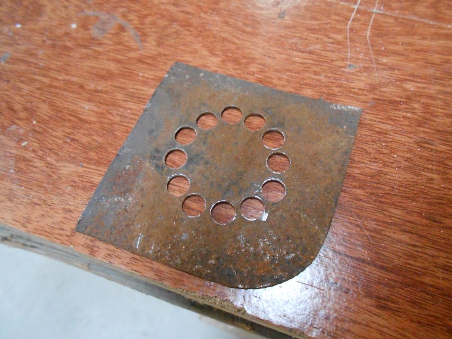
metal plate drilled
Put the bolts :
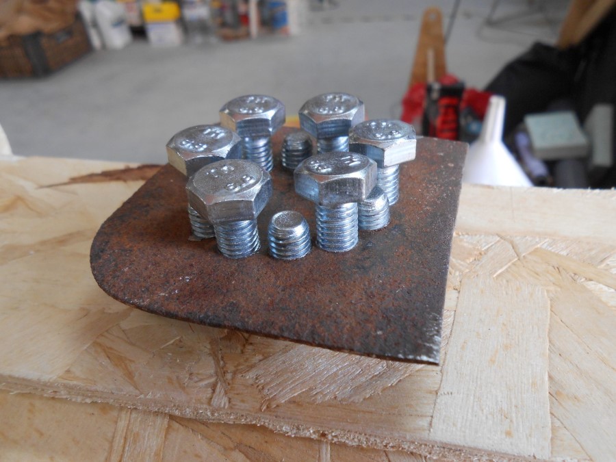
Bolts through the holes
And weave the Nitinol in between :
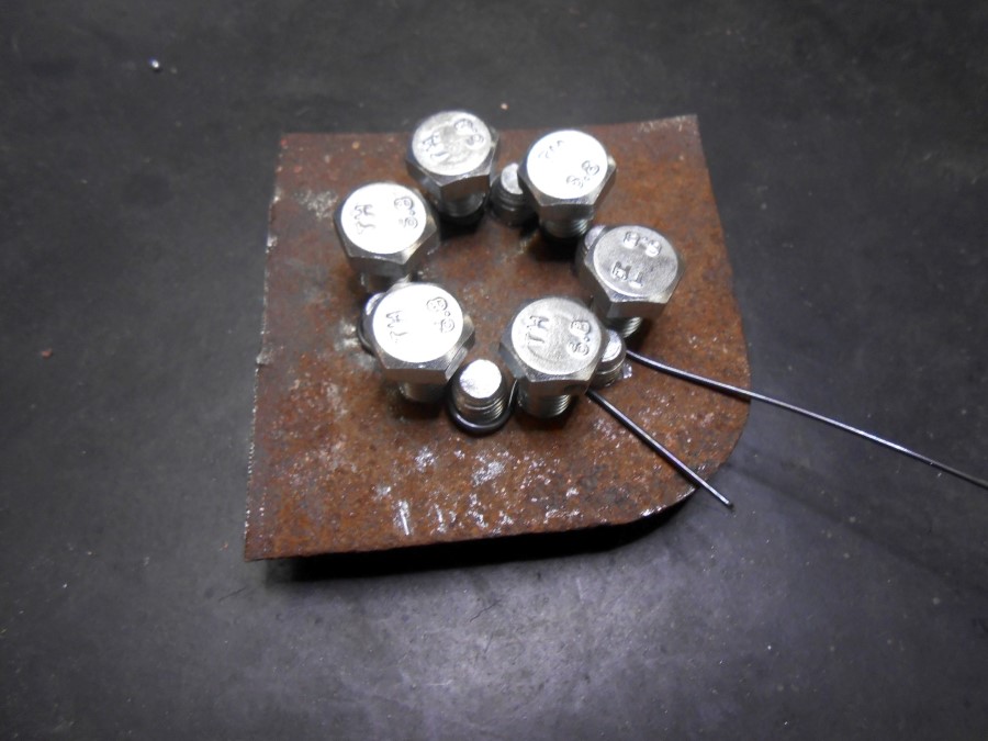
Nitinol wire woven in between the bolts
I quench it after annealing :
Quenching
And remove the bolts...
Liberating the Nitinol !
I do this twice to start with and I then have my freshly annealed Nitinol, in the contracted position :
Nice earings
Now I put them back into the circular (expanded) position :
Nitinol rings put back into expanded shape
I then lay them around the first layer of silicone I applied around my pump shell form :
Pin to maintain the nitinol wires in place
Coat another layer of silicone so that the Nitinol is sandwiched in between the two layers :
taking the ring out of the form
Here is an example of the many test rings I did :
Ring ready for testing
And here is the contraction by having electricity going through it :
Video of the Nitinol Driver Board driving Nitinol springs
Here is an example with two wires :

2 Nitinol rings experiment
But the silicon is too thick on this one to allow the Nitinol to contract properly :
contraction prevented by a too high thickness
And here I ran out of time to go further into finding a valid set of parameters for Silicon / Nitinol to properly contract.
Souce Files
Here are the sources files of the projects I talked about in this section :
Parametric Nitinol annealing holder file for Grasshopper
Driver Board
In this section we design and make the electronic driver board to run the electricity through the Nitinol wire in order to heat it up and make it go back to its shape.
Here is the process of development for the board :
driver board development process
I draw the Schematic with Eagle :
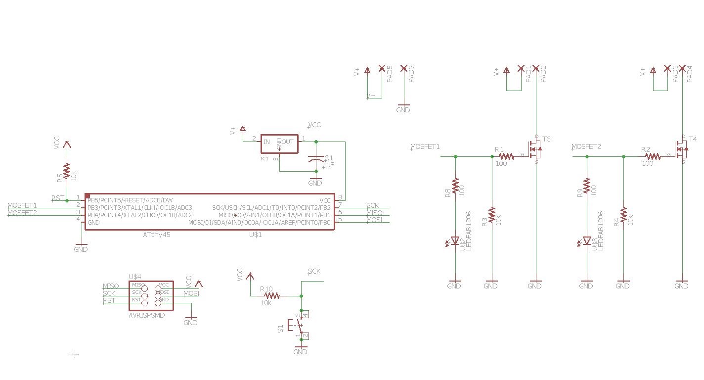
Schematic
Make the Layout :
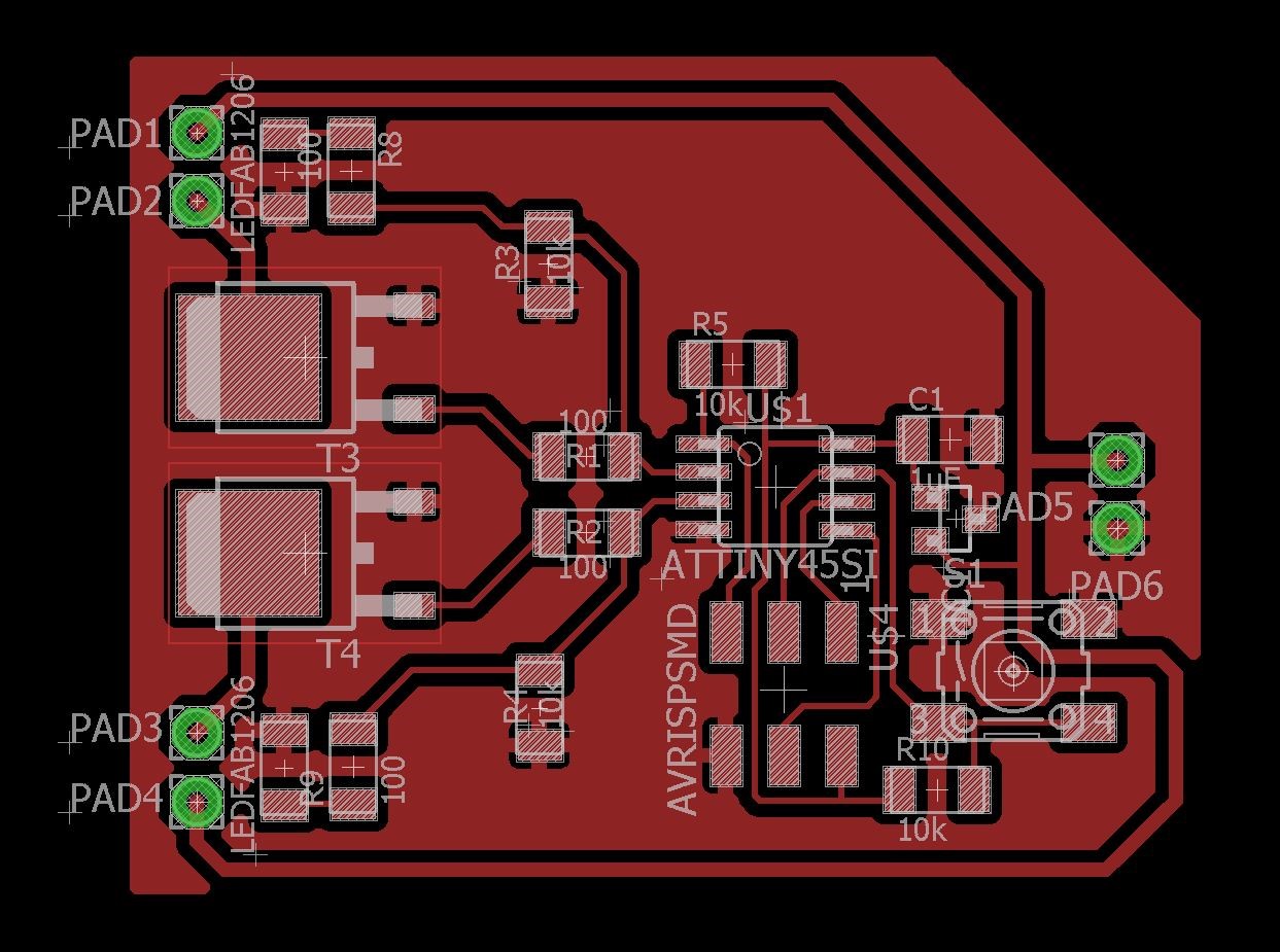
Layout
Populated it :
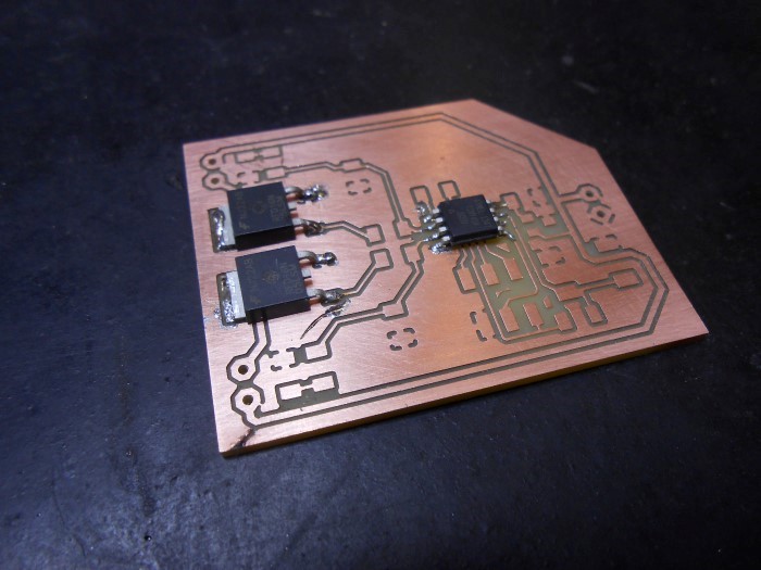
Soldering
Now, to validate the board, I will do a two Nitinol wire test :
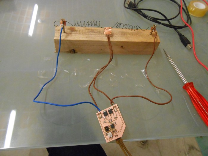
Testing alternative motion
Video of the Driver Board in action :
alternating pull motion
Souce Files
Here are the sources files of the projects I talked about in this section :
Driver board traces PNG for fabmodules.org
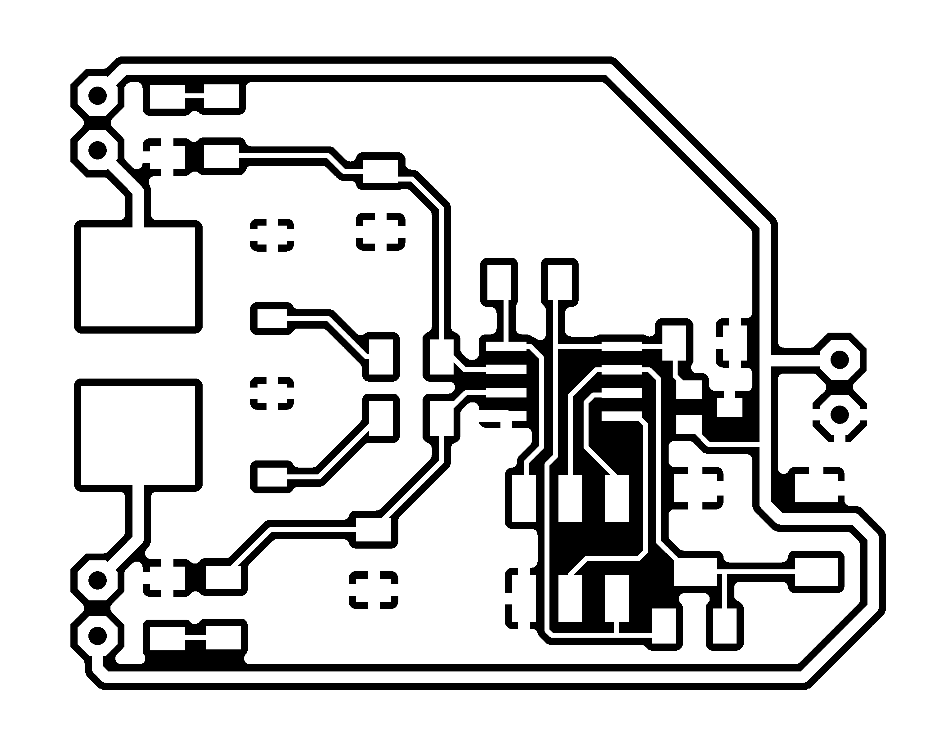
Driver board outline PNG for fabmodules.org
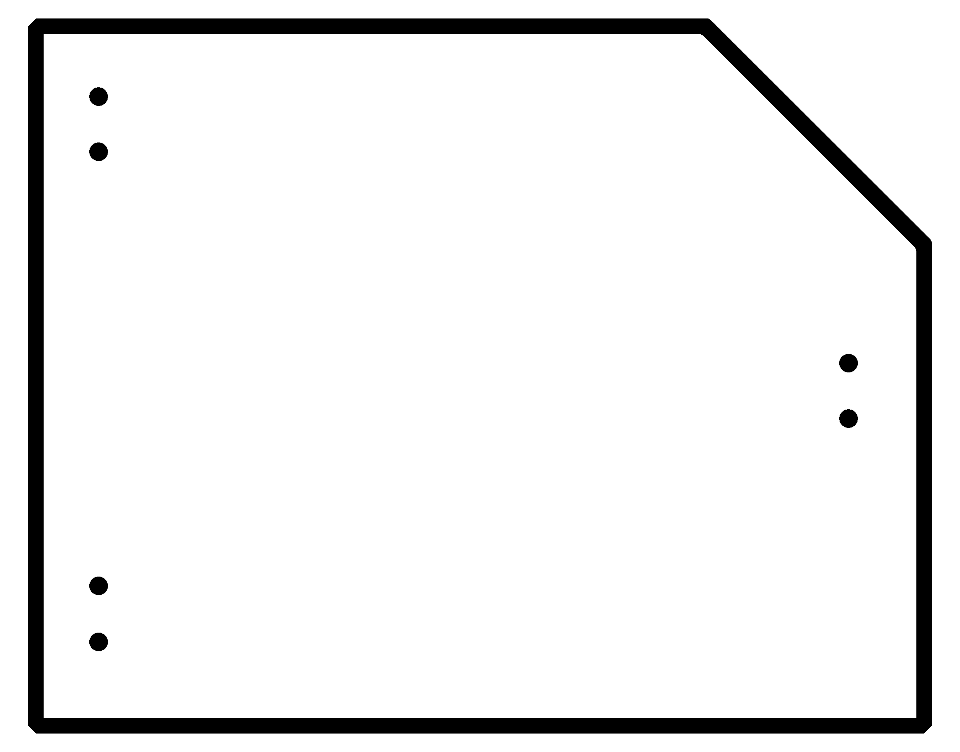
Driver board schematic for EAGLE
Driver board layout for EAGLE
***