Program "hello-world" board to do something
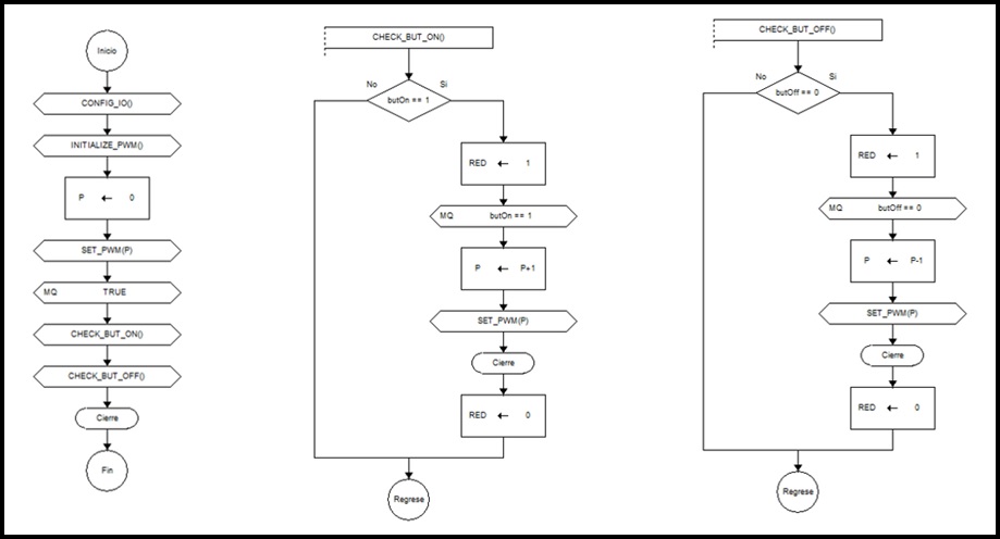
Flow Diagram
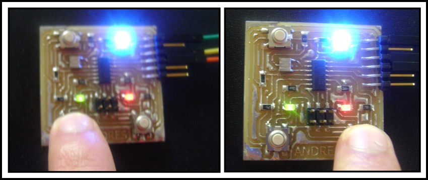
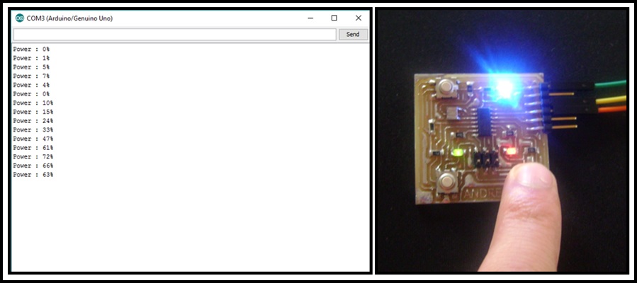
My "hello-world" PCB has a button with pull-up resistor, a button with a pull-down resistor and a red led connected to digital I/O pins; also has a green led connected to a PWM output and has a serial communication port.
My algorithm consist in increase the brightness of green Led when one button is pressed and decrease the brightness when the other button is pressed. The red Led will turn on when any button is pressed, and the percentage of brightnes shuold be transsmitted by serial interface when any button is released.
You can see the flow diagram of my algorithm.
Programming with Arduino IDE
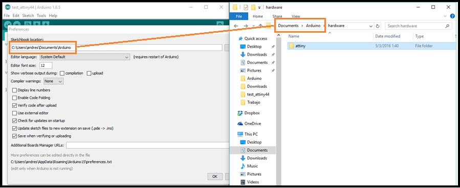
1.- Download and copy ATtiny board files on Arduino preferences path. Remember to create hardware folder.
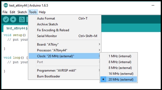
2.- Go to Tools and configure the board:
2.1.- Board: "ATtiny"
2.2.- Processor: "ATtiny44"
2.3.- Clock: "20 MHz (external)"
3.- Go to Tools, click on Programmer and select USBtinyISP.
4.- Connect FabISP with "hello-world" PCB through the SPI interfcae and go to Tools and click on Burn Bootloader. In this step the Arduino IDE set the fuses of ATtiny44 to work with external crystal at 20MHz.
5.- Encode and compile the algorithm.
#include <SoftwareSerial.h>
SoftwareSerial serial(1, 0);

const int LED_RED   = 3;
const int LED_GREEN = 7;
const int BUT_ON    = 2;
const int BUT_OFF   = 8;

int power = 0;

void setup() {
  // put your setup code here, to run once:
  serial.begin(9600);

  pinMode(LED_RED,   OUTPUT);
  pinMode(LED_GREEN, OUTPUT);
  pinMode(BUT_ON,    INPUT);
  pinMode(BUT_OFF,   INPUT);

  analogWrite(LED_GREEN, power*255/100);
  serial.println("Power : 0%");
}

void loop() {
  // put your main code here, to run repeatedly:

  if(digitalRead(BUT_ON) == 1){

    digitalWrite(LED_RED, 1);
    while(digitalRead(BUT_ON) == 1){
      delay(50);
      if(power < 255)
        power++;
      analogWrite(LED_GREEN, power);
    }
    digitalWrite(LED_RED, 0);

    serial.print("Power : ");
    serial.print(power*100/255);
    serial.println("%");
  }

  if(digitalRead(BUT_OFF) == 0){

    digitalWrite(LED_RED, 1);
    while(digitalRead(BUT_OFF) == 0){
      delay(50);
      if(power > 0)
        power--;
      analogWrite(LED_GREEN, power);
    }
    digitalWrite(LED_RED, 0);

    serial.print("Power : ");
    serial.print(power*100/255);
    serial.println("%");
  }
}
6.- Upload the firmware.
Programming with Atmel Studio 7
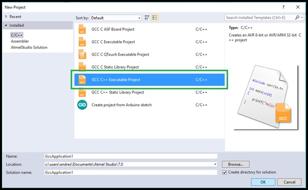
1.- Open Atmel Studio, go to File, select New and click on Project.
2.- Select GCC C++ Executable Project and click on OK button.
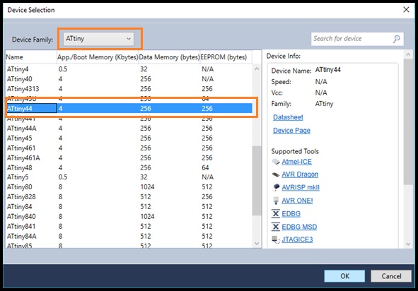
3.- On Device Family tab select ATtiny, choose Attiny44 and click on OK button.
4.- Encode the algorithm.
/*
 * test_attiny44.cpp
 *
 * Created: 23/3/2016 16:28:43
 * Author : Andres Moreno
 */

#define F_CPU 20000000UL

#include <avr/io.h>
#include <util/delay.h>

#define sbi(reg, bit) (reg |=  (0x01 << bit))
#define cbi(reg, bit) (reg &= ~(0x01 << bit))
#define rbi(reg, bit) (((reg >> bit) & 0x01) ? 1 : 0)

#define BUT_ON		PINA2
#define BUT_OFF		PINB2
#define LED_RED		PINA7
#define LED_GREEN	PINA3

void init_PWM0B()
{
	TCCR0B |= (1<<FOC0B)|(1<<CS01)|(1<<CS00);		// enable OCR0B pwm output and set clk/8
	TCCR0A |= (1<<COM0B1)|(1<<WGM01)|(1<<WGM00);	// set OCR0B as pwm
}

void set_PWM0B(unsigned char value)
{
	OCR0B = value;
}

int main(void)
{
    DDRA = 0b10001000;	//PA7 and PA3 as outputs and others are inputs
	DDRB = 0b00000000;	//PORTB as input

	unsigned char power = 0;
	init_PWM0B();
	_delay_ms(5);
	set_PWM0B(power);

	while (1)
    {
		if(rbi(PINA, BUT_ON))
		{
			sbi(PORTA, LED_GREEN);
			while(rbi(PINA, BUT_ON)){
				_delay_ms(5);
				if(power < 255)
					power++;
				set_PWM0B(power);
			}
			cbi(PORTA, LED_GREEN);
		}

		if(!rbi(PINB, BUT_OFF))
		{
			sbi(PORTA, LED_GREEN);
			while(!rbi(PINB, BUT_OFF)){
				_delay_ms(5);
				if(power > 0)
					power--;
				set_PWM0B(power);
			}
			cbi(PORTA, LED_GREEN);
		}
    }
}
5.- Go to Build and select Build Solution or press F7 for compile the algorithm.
6.- For upload the firmware, you need to search HEX file (is in Debug folder). In this path you should open command prompt and upload firmware. You can see an example on Electronic Production week.