Assignments
The assignments for week 8 was to read the data sheet for the Atmel 8-bit AVR microcontroller and program our board from week 6 to do something with as many different programming language and programming environments as possible
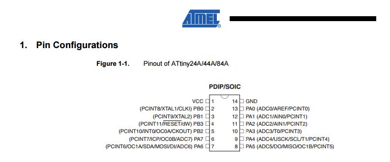
The datasheet
I started off by loosely reading the 286 page datasheet fot the Atmel 8-bit AVR microcontroller
It was a brand new thing for me to read a data sheet like this put it gave me more information on how the microcontrollers pins work
The image below gave me some understanding of the roles of each pin on the microcontroller
Programming the board
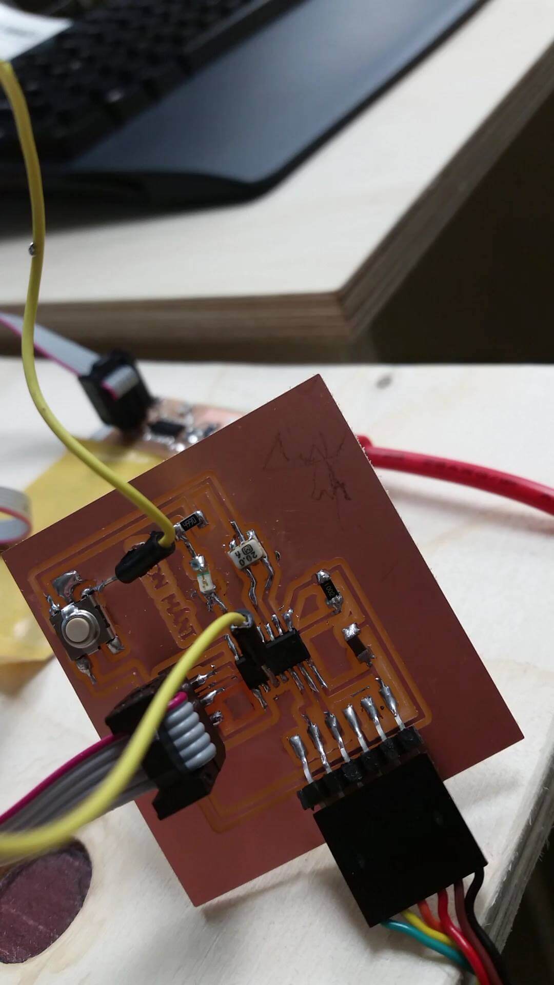
I ran into a problem straight away when i plugged the avrISP to my board from week 6
The avrISP showed an orange light and the led turned on when it was plugged in
Something wasn´t right so i decided to make another board
The instructor in Reykjavík had pointed us out in week 6 that the resistor connected to the pushbutton was not necessary
So for my new design i removed that resistor and also added my name to the board
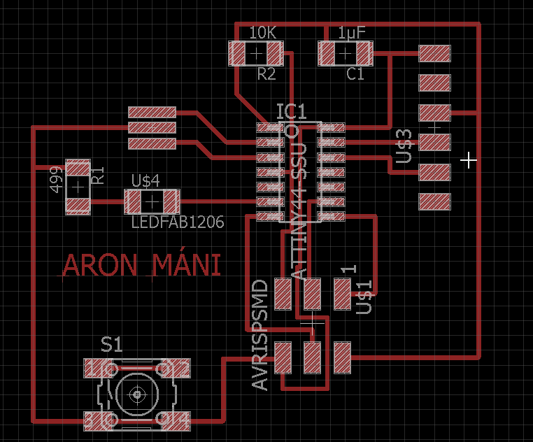
This time the avrIsp showed a green light and i was very pleased!
But my problems weren´t done yet....
I decided to use the arduino enviroment to program my board
I downloaded the software from the Arduino website
My friend Baldvin pointed me to a good tutorial on how to program an ATtiny45, ATtiny85, ATtiny44 or ATtiny84 microcontroller using the Arduino software
After i had read the tutorial i opened the arduino software and plugged the fab isp and my board in
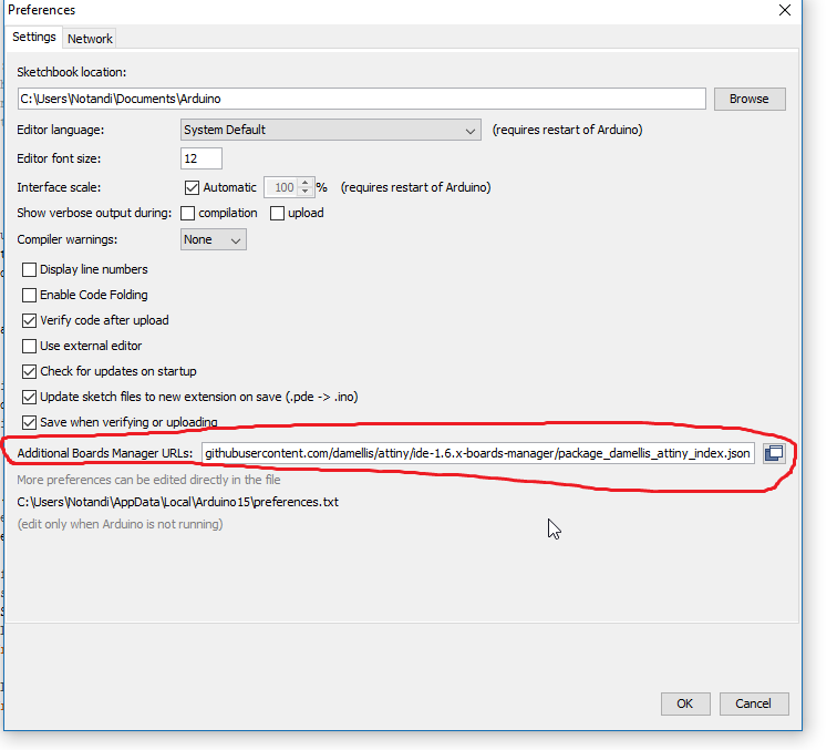
I had to start off by installing the attiny support for arduino
To do so i opened the preferences dialog in the arduino software and found the “Additional Boards Manager URLs” field near the bottom of the dialog
I had to paste the following URL into the field: https://raw.githubusercontent.com/damellis/attiny/ide-1.6.x-boards-manager/package_damellis_attiny_index.json and then click the OK button to save my updated preferences
Next i opened the boards manager, searched for the attiny and finally installed it
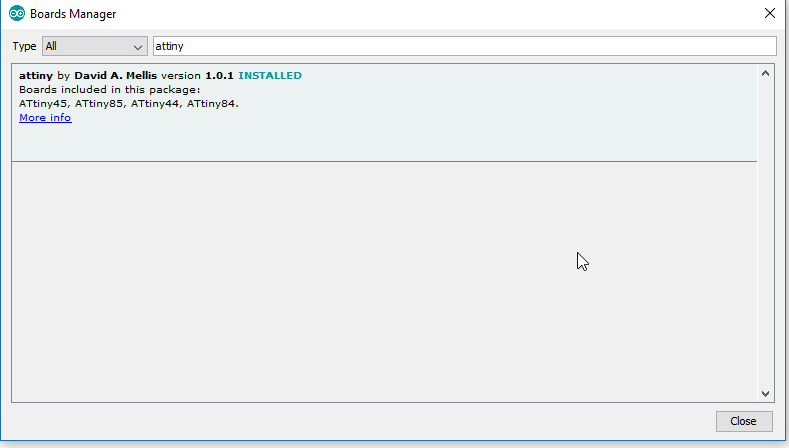
Now the ATtiny was visible in the boards menu
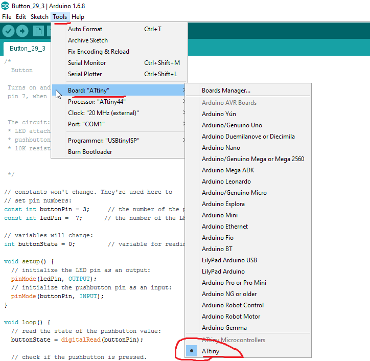
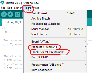
And now i could choose the correct processor and clock, in my case the Attiny44 and a 20 Mhz clock
Now i thought i was ready to program my board
I was told that the pins on the microcontroller do not match the pins in an Arduino
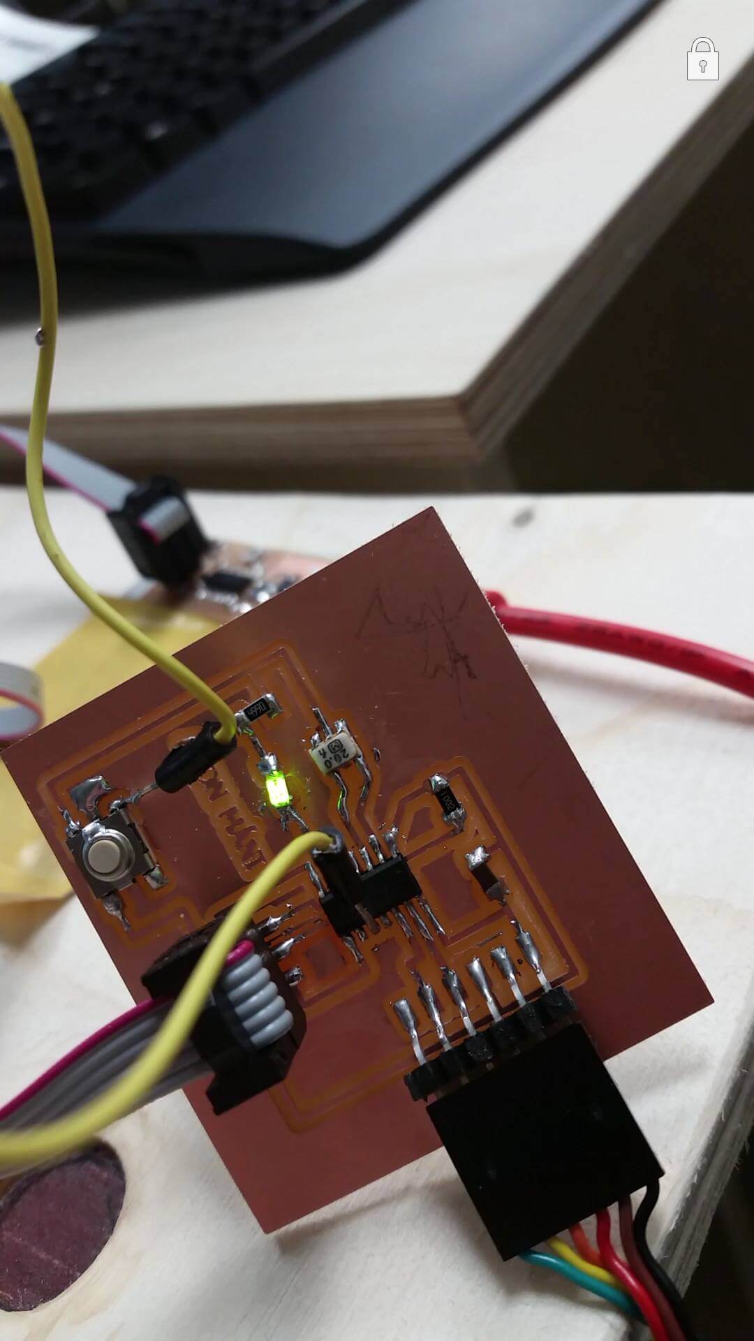
When i started to compare the pins of the microcontroller and the arduino ones i spotted one mistake i had made
The pushbutton wasn´t connected to the microcontroller. I was supposed to connect the pushbutton to pin 10 on the microcontroller
I found a jumper wire and soldered them together
Now i had to tell the arduino software the pins i was using
The image below shows you the conversion of the pins from the Attiny to arduino
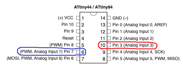
The analog inputs are the ones we use in the arduino enviroment
So my LED was pin 7 in arduino and the button was pin 3
Now i decided to run the blink example in arduino to see if my led worked
I changed the pins so they would match my board and uploaded the program
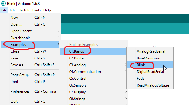
The upload went good and i had no errors in the program, but i had another problem awaiting now. The LED didn´t blink...
The first thing that came in mind was that the led was turned the wrong way
I desoldered it and soldered it back now turning the other way
I ran the program again and this time the LED blinked and i was very pleased with that
Since i had little experience with programming in C i decided to start off by program the board with a simple program
I made program that turns the LED on when the button is pressed, very similar to the basic button example in arduino
Files from week 8
Embedded programming in Final Project
I also did some embedded programming in my final project
You can read more about it in on my final project development page (link)