Assignments
-Complete your final project, tracking your progress:
What tasks have been completed, and what tasks remain?
What has worked? What hasn't?
What questions need to be resolved?
What will happen when?
What have you learned?
Original idea and getting new ideas
As i mentioned some weeks ago my final project idea changed midway through the academy
My original final project proposal was to make a synthesizer
But in the group week when we were supposed to make a machine using stepper motors i got an idea
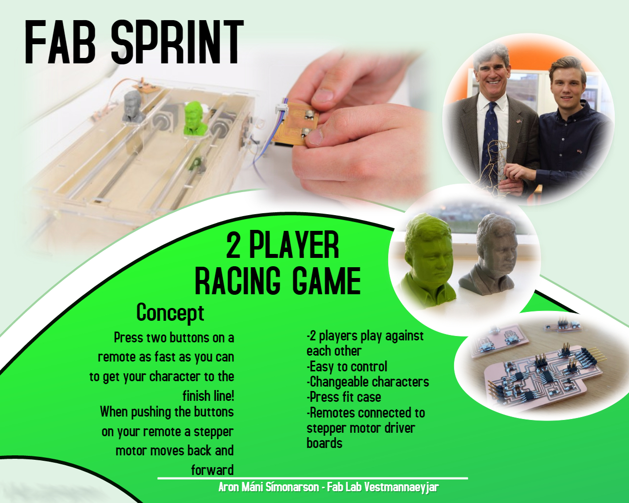
When i thought about implementing stepper motors into a machine i got this idea of a "two player race game"
My original idea is very similar to the prototype i made in the end
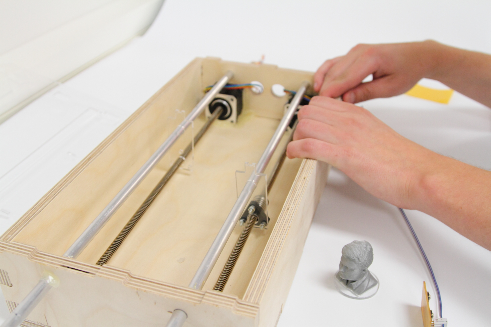
I wanted to fasten two seperate objects to two stepper motors
When a button was pressed the object of each stepper motor would move
The faster you would push the button the faster the object goes
So straight away i had this race game idea going on
The first object/character to reach a finish line wins the game
Here´s the original sketch i drew straight after i got the idea
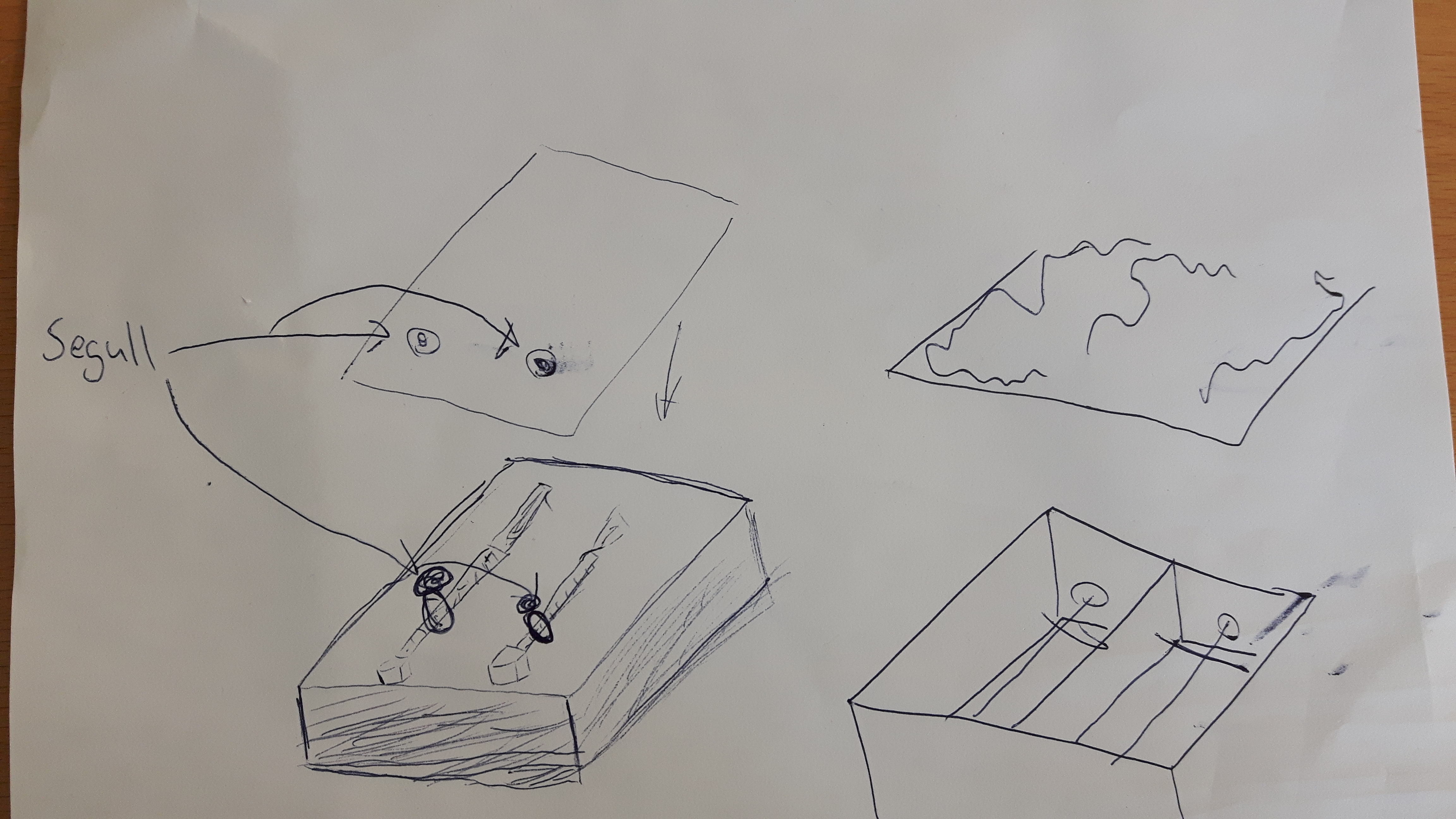
At this stage my plan was to make a case/box around the stepper motors, the electronics boards and the cables and put a plate on top of the box
I wanted to make some kind of holder with a magnet on top of it so i could put another magnet on the plate and move the magnets back and forward and some kind of object/character would be fastened to the magnet
When i got closer to the final weeks of the academy i let go of the magnet idea and wanted to make holes in the plate so an object/character could move back and forward through that hole, sticking up from the stepper motor screw
I was determined to have the case around the stepper motors a press-fit case so i could implement skills from the computer-controlled machining week
Designs and processes
After i was happy with my final project concept i was clear to begin the design of the parts i needed for the project
I will describe the process of each part and tell what program or machine i used to create the objects
Wooden Press-fit box
As i mentioned above i needed to build a box around the stepper motors and the circuit boards
I decided to draw the box in sketch up
Sketch up is very handy if you are aiming to draw press-fit items
I also used sketch up to design a speech desk in week 7 so i had already picked up some skills in press-fit design in sketch up
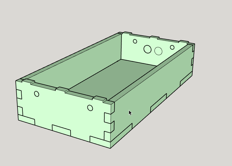
I drew up joints so the box would fit together
After the box itself was ready i had to design holes for the two poles(The one´s we received in the machine group week) and so the wires from the stepper motor could go outside the box
I measured the distances between the poles and the holes for the stepper motor wires and made decent sized holes
Here´s how the design looked like after the designing in sketch up
Now with the designing process finished i could move my file to a vectric program and after that cut the box out
I used the program VCarve Pro to import my box to a vectric form and create toolpaths for the cutting
Further details on how to use VCarve Pro and the shopbot can be found in week 7
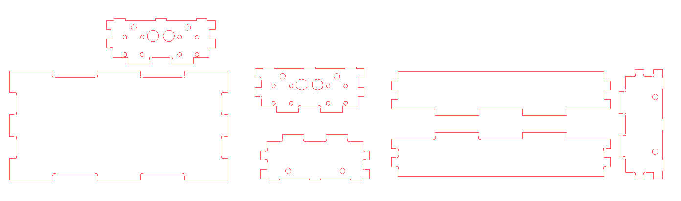
I used the dog bone fillet feature just like in week 7 to make it easier for the joints to fit together
Here´s what the vector file looked like in VCarve Pro
After i had sorted out all the toolpaths in VCarve Pro i was clear to go to the shopbot and cut the box out
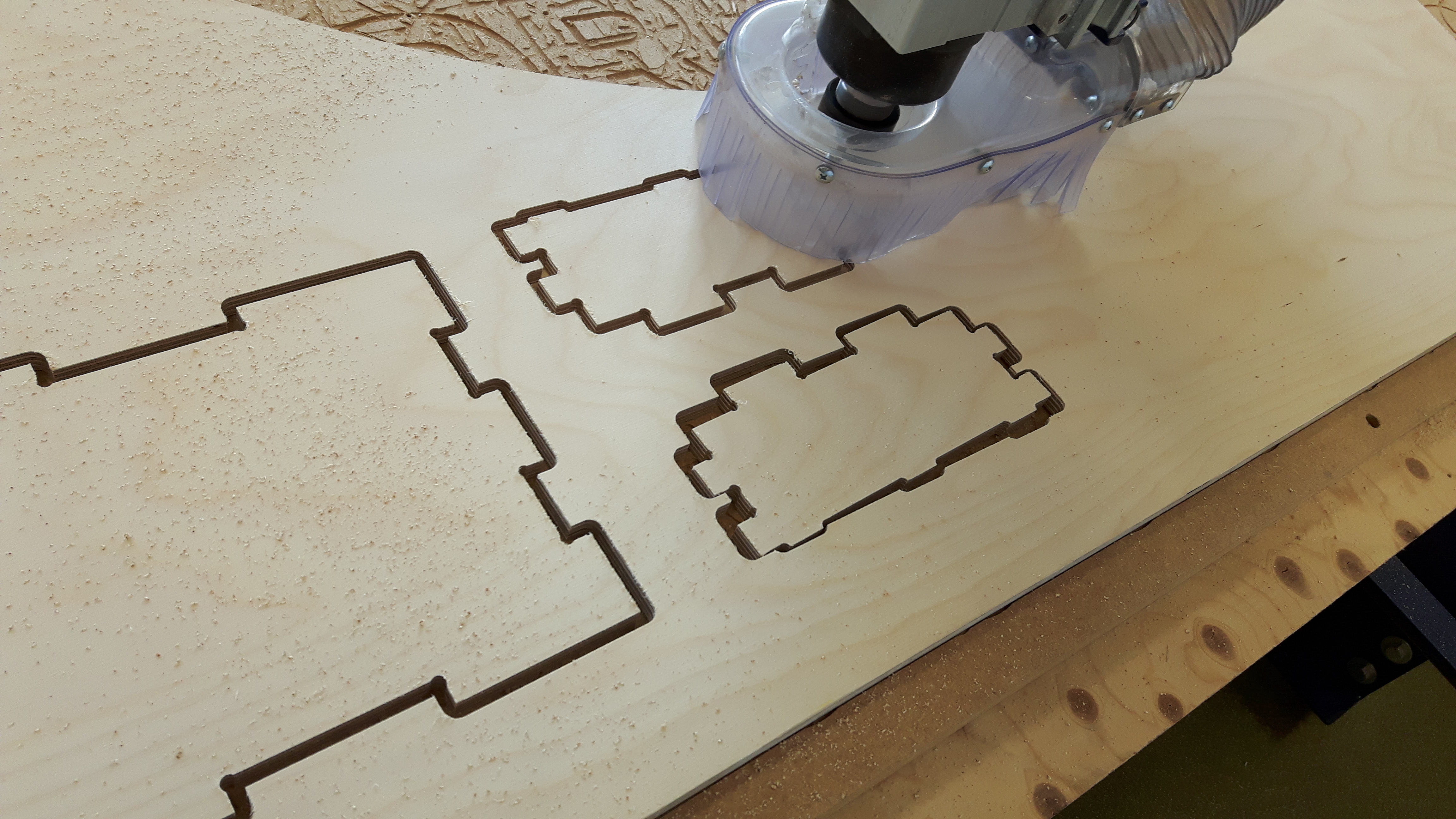
I was very happy with the result and the pieces fitted perfectly together
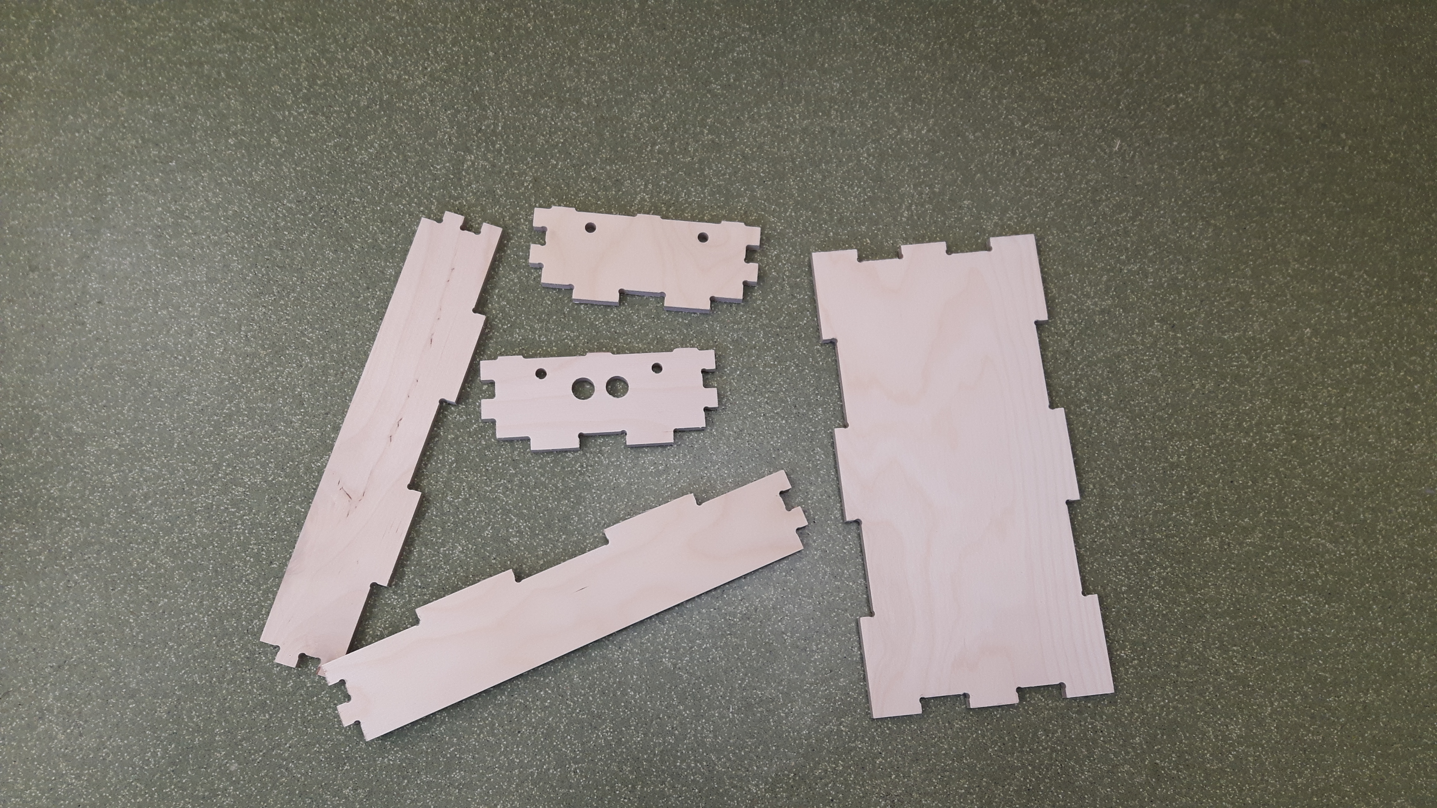
The stepper motors and the poles fitted perfectly and the holes were in the right places
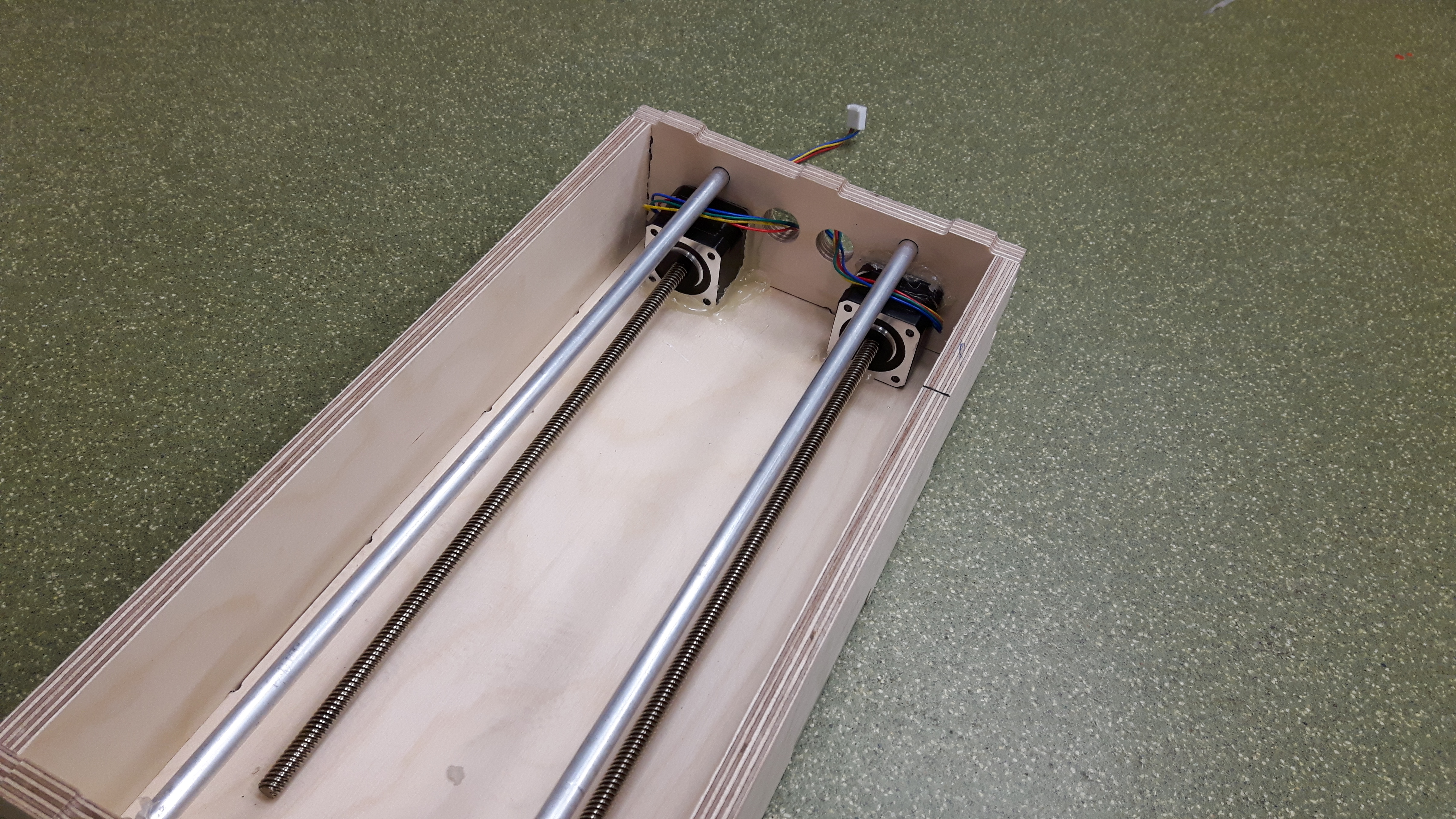
I glued the motors and the poles in this first version of the project but that was just a temporary solution
Plexi glass plate
I needed to design and make a plate that would fit onto the wooden box
I had to design the plate that would have space for my 3d printed characters to stand out of the plate
I designed the plate in inkscape, a vector program we use alot in our lab
Information on designing in inkscape can be found in week 3
I added extra joint slots to the plate for future installations
I made sure that the plate would fit on to the press-fit box
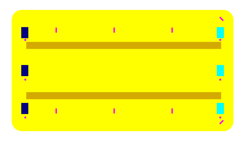
The long brown lines are the holes/track length for the 3d printed characters moving back and forward
I used the laser cutter to cut the plate out. Laser cutter instructions can be found in week 2
When you are cutting out an item for the first time it´s always better to start off by cutting out a prototype using cheaper material
In my case i started off by cutting out my plate in cardboard paper
Happily enough it fitted perfectly so i was clear to cut out the plexi glass plate
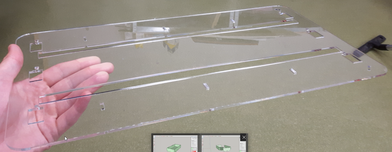
I decided to go with transparent plexi glass for my prototype to let people see whats going on underneath the plate
I was happy with the result and the plate and the box looked quite nice together
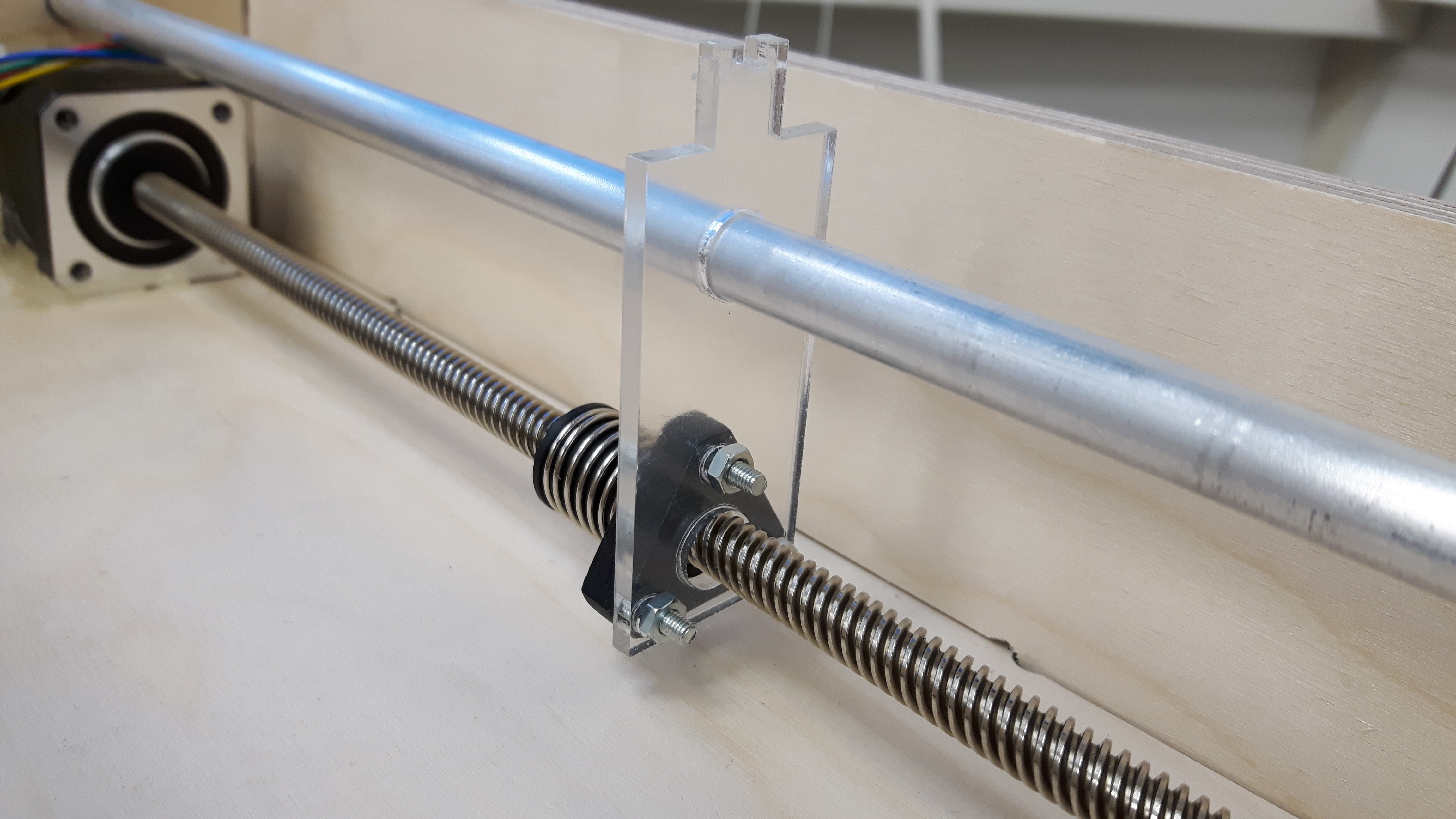
Plexi holder unit
I needed to design a unit that would fit to the screw on the stepper motor that included two holes, one for the pole and for the unit that fits onto the motor screw
Again i used inkscape to design the unit
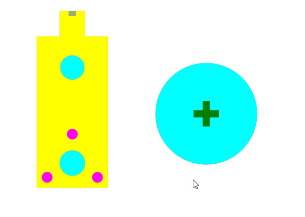
The circle is the plate/stand for the 3d printed character
The plate then press fits onto the unit
The three pink holes are made for screws to fit into
Here´s what the unit looks like on the motor. I was happy with the result
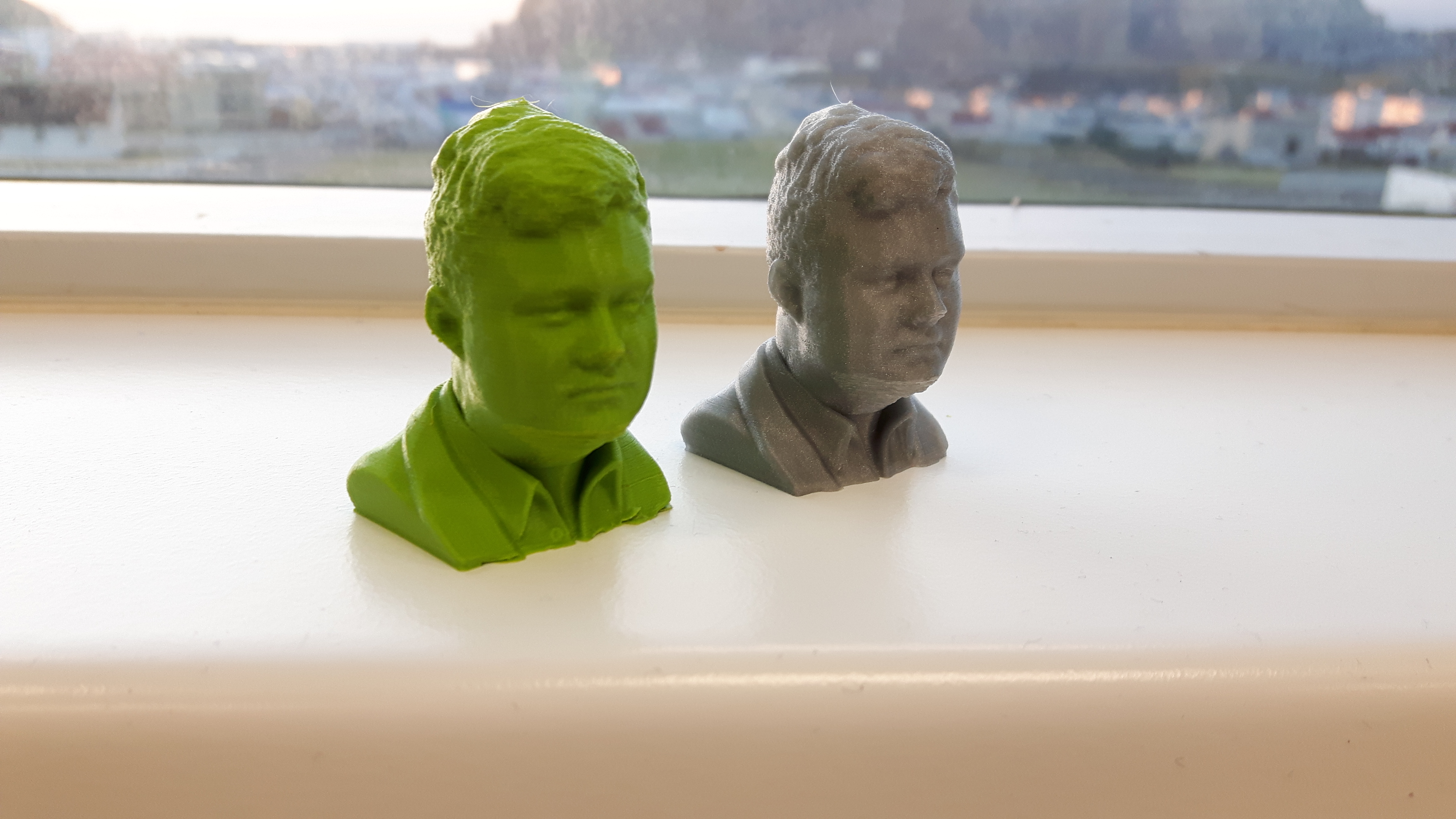
3d printed characters
In week 5 i 3d scanned my friend so i thought it was ideal to use his face as the main character in the sprint race
I did go over the 3d printing progress in week 5 information can be found there
I was very happy with the result of the 3d printing
Electronics
Stepper motor driver boards
I knew that i wanted to drive a stepper motor using buttons to control the steps
I had to design and make one driver board and one button board for each stepper motor
I used Eagle to design the boards like earlier in the academy
I decided to design my board based on Neil´s stepper motor board
He uses A5953 H-Bridges to drive his stepper motor
Those H-Bridges were available in my lab so i also decided to use them for my board
I did some research on H-Bridges on the internet and was able in the end to understand what each pins does
Here´s the diagram for the A4953 H-Bridge
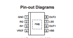
I used the Attiny44 microcontroller for my board
The pins on the Attiny44 were well used as i only left one pin unused
I used 2x4 pin headers to power the board
I included FTDI pins for future interface options
The instructor in Fab Lab Reykjavik pointed out that i could use the AVR pin headers for antother purpose then just programming it
I connected MISO and MOSI on the AVR pins to the microcontroller for future extra board add ons
Here´s the schematic for the stepper motor driver board
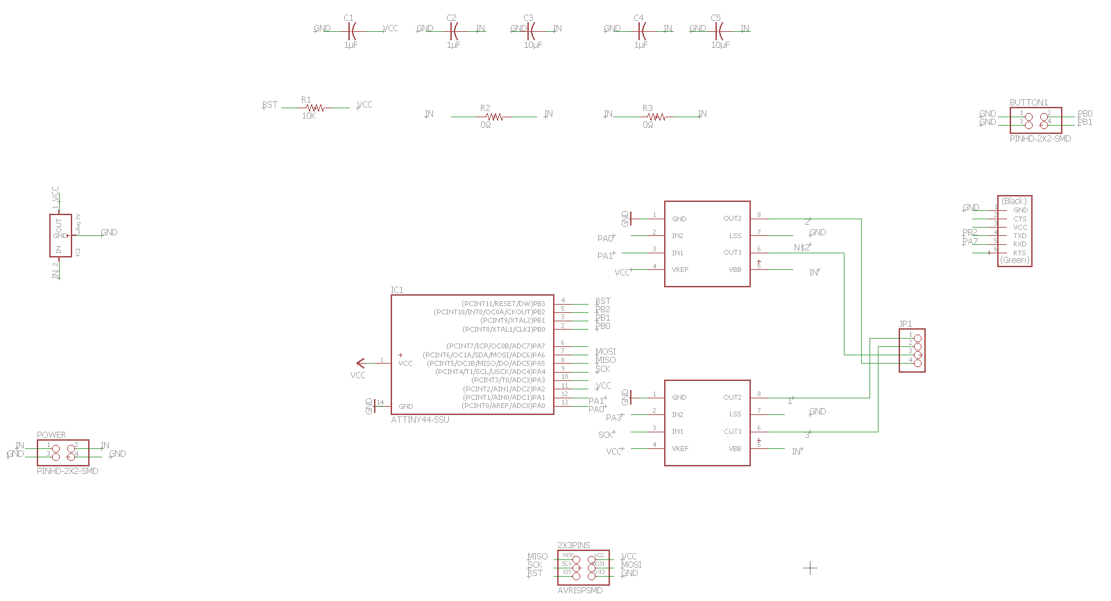
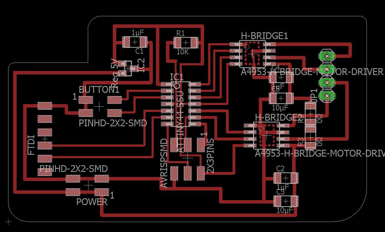
Here is the board layout after i finished routing it
I decided to drill holes for the FCI connectors for the stepper motor
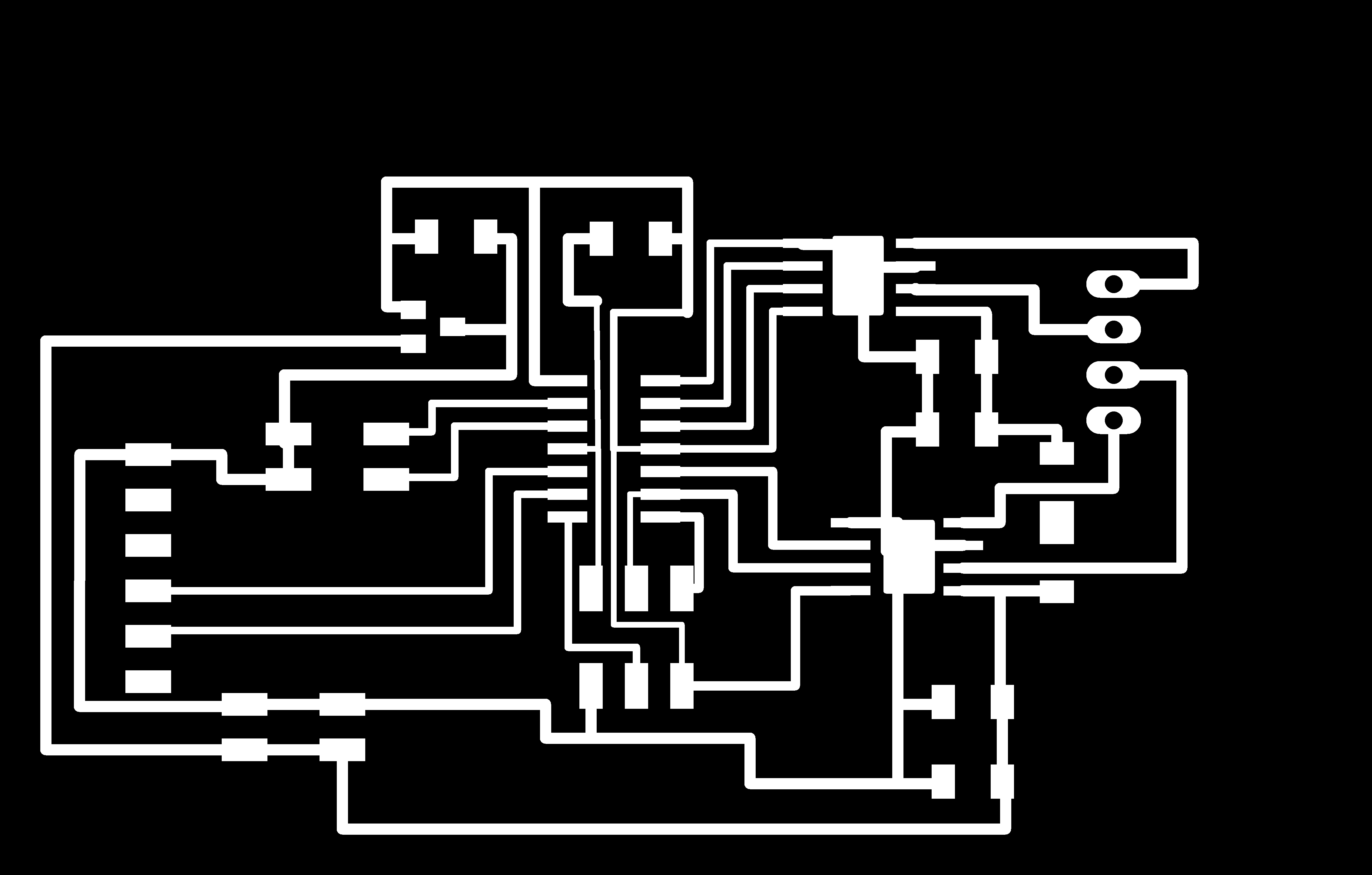
Here below are the traces and outline images

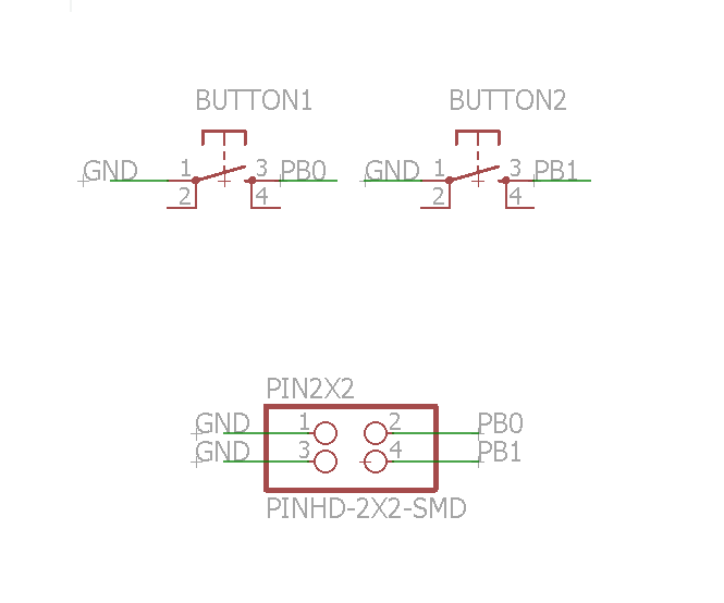
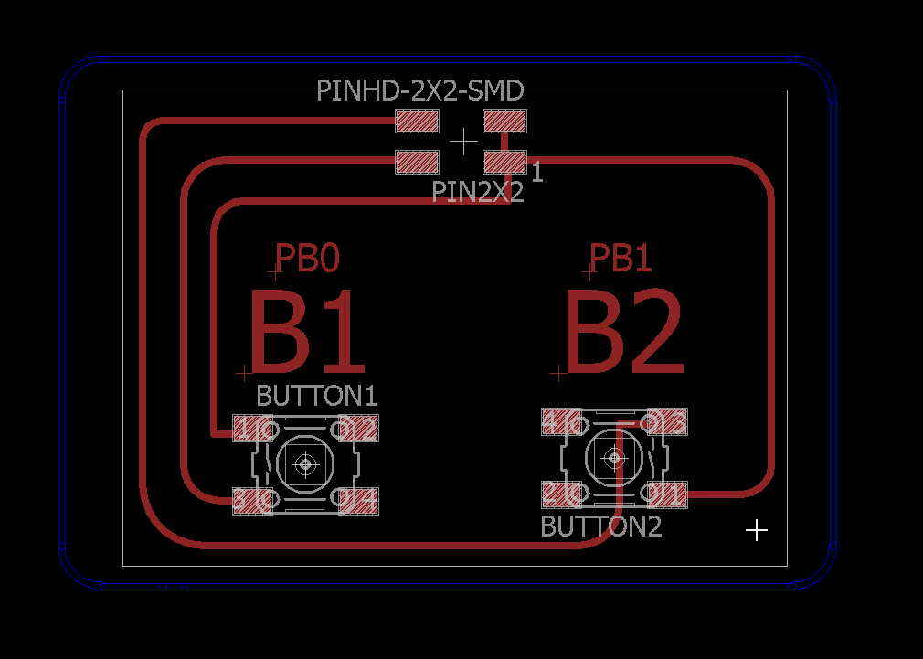
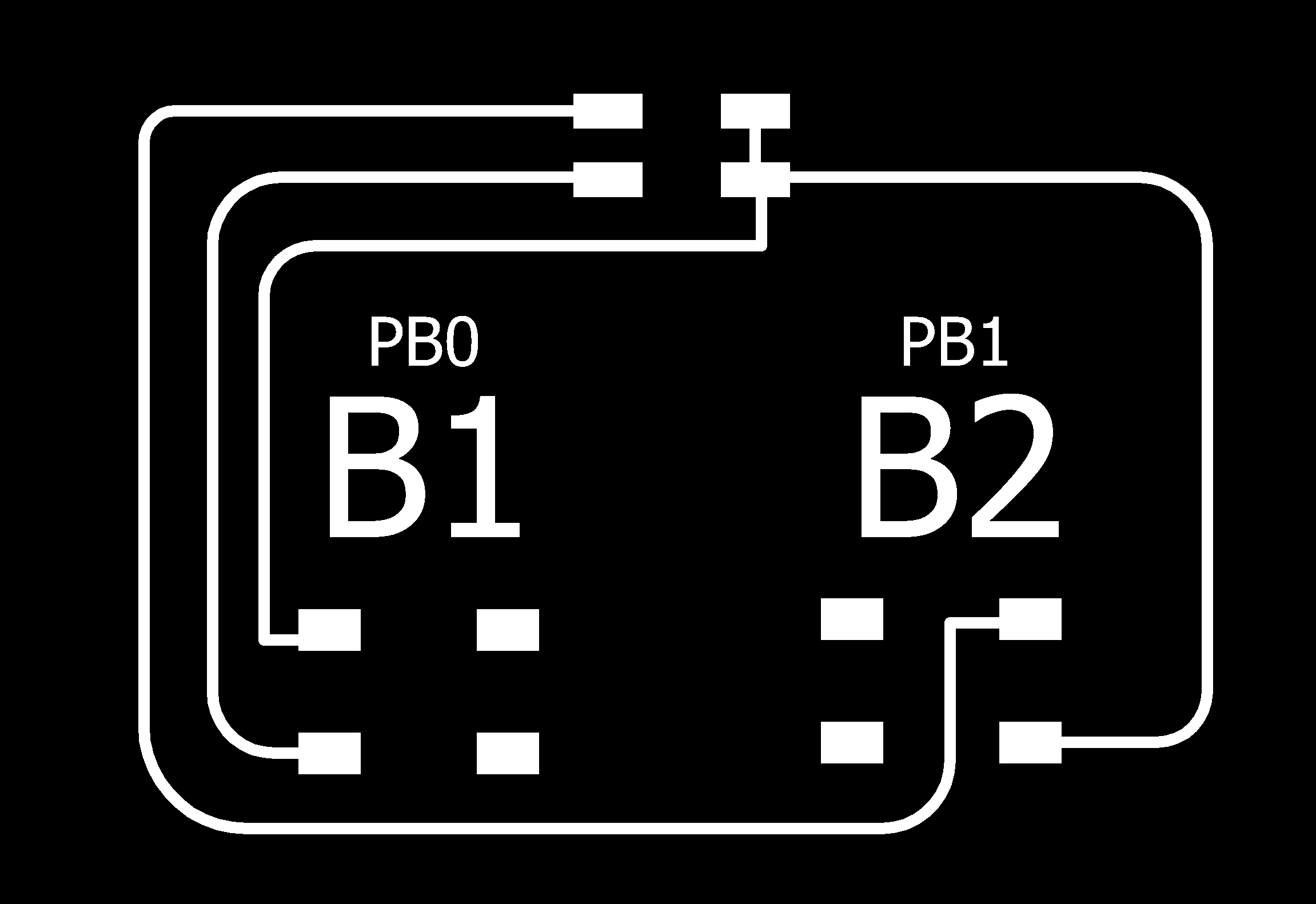
Button boards
I designed a simple button board with two buttons on it and 2x2 pins that were connected to my main stepper board
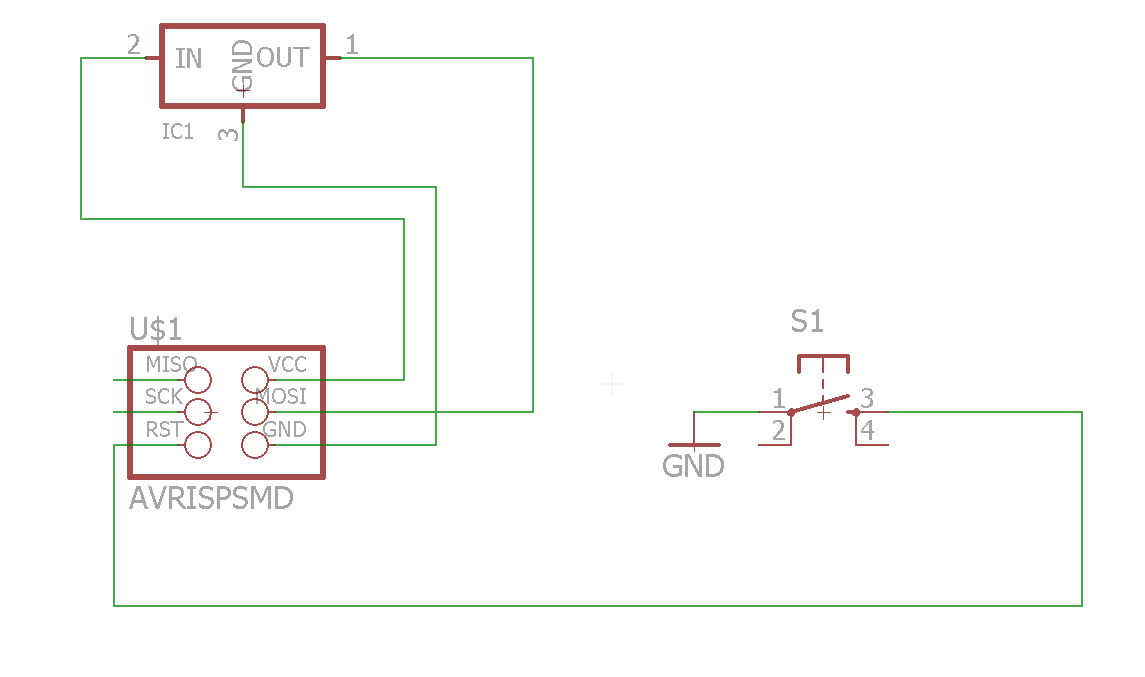
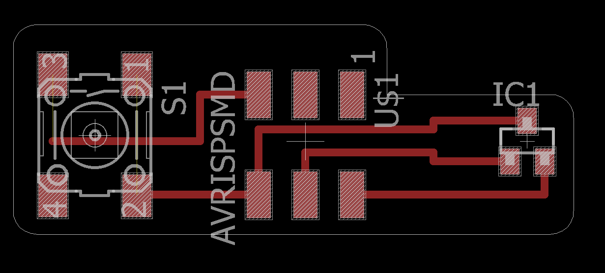
Hall sensor boards
I had not time to finish the installation of these boards to my prototype but i was able to finish the design and soldering
The purpose of the hall sensor board is to detect when a character reaches a certain distance. The hall sensor would then notify when a magnet is near him and i could program the motor to move the character backwards it reaches the hall sensor board
The hall sensor board connects to the motor board via the AVR pins
The board only includes a hall sensor, one button and 2x3 fci pins
Here is the schematic and the board
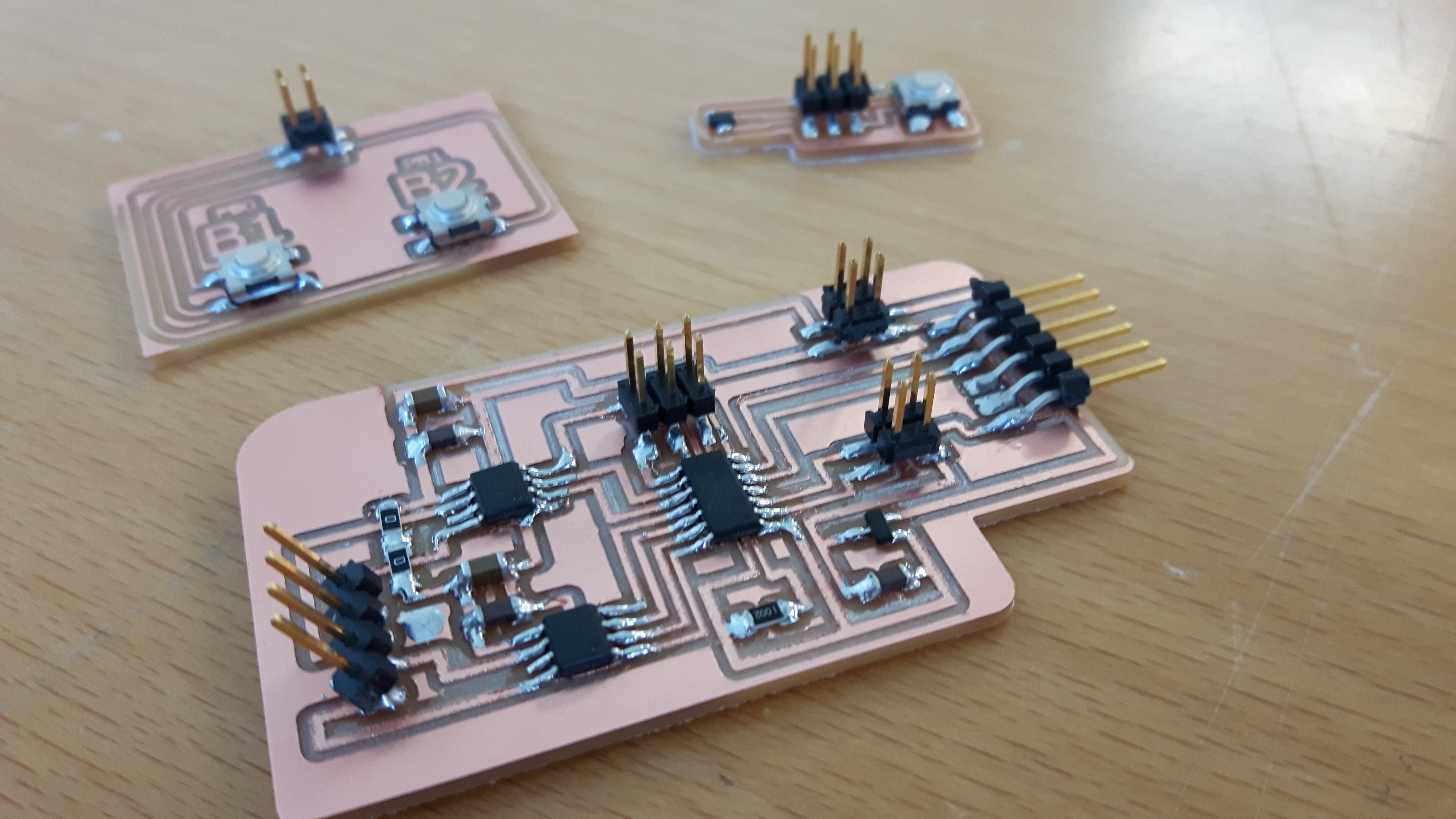
Here are my three boards for one stepper motor after i had soldered them
Powering the boards
I needed to get at least 12V to power the boards and get the motor spinning
I found an old dell laptop charger and soldered a 2x2 header to the end so it would fit on my board
.jpg)
.jpg)
Luckily enough this modified charger worked and i was clear to go to the programming part
Programming
I used the arduino enviroment to program my board
I was able to verify my code right from the beginning but had problems when i uploaded the code to my board
The upload was successful but the motor simply just didn´t move when the buttons were pressed
I searched for help from the great instructor of Fab Lab Reykjavík Bas Withagen, who gave me great advice on my final project before
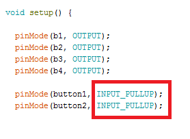
He pointed out that the pullup resistor wasn´t defined in the code and that was exactly the problem!
I activated the pullup resistor and finally got my stepper motor moving by pushing buttons on a board
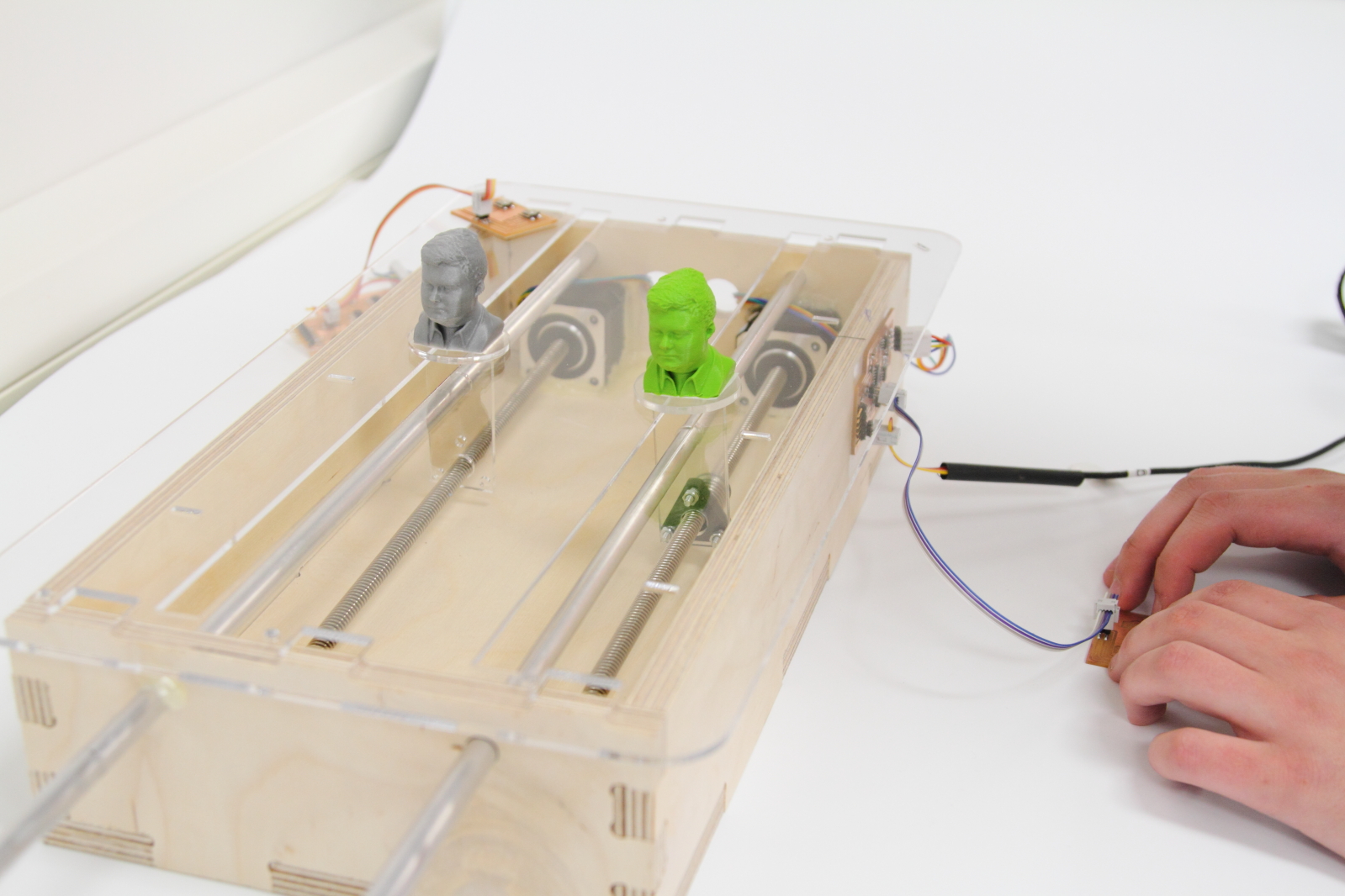
When i had the programming finished i puzzled my whole machine together and this was the outcome

