Project
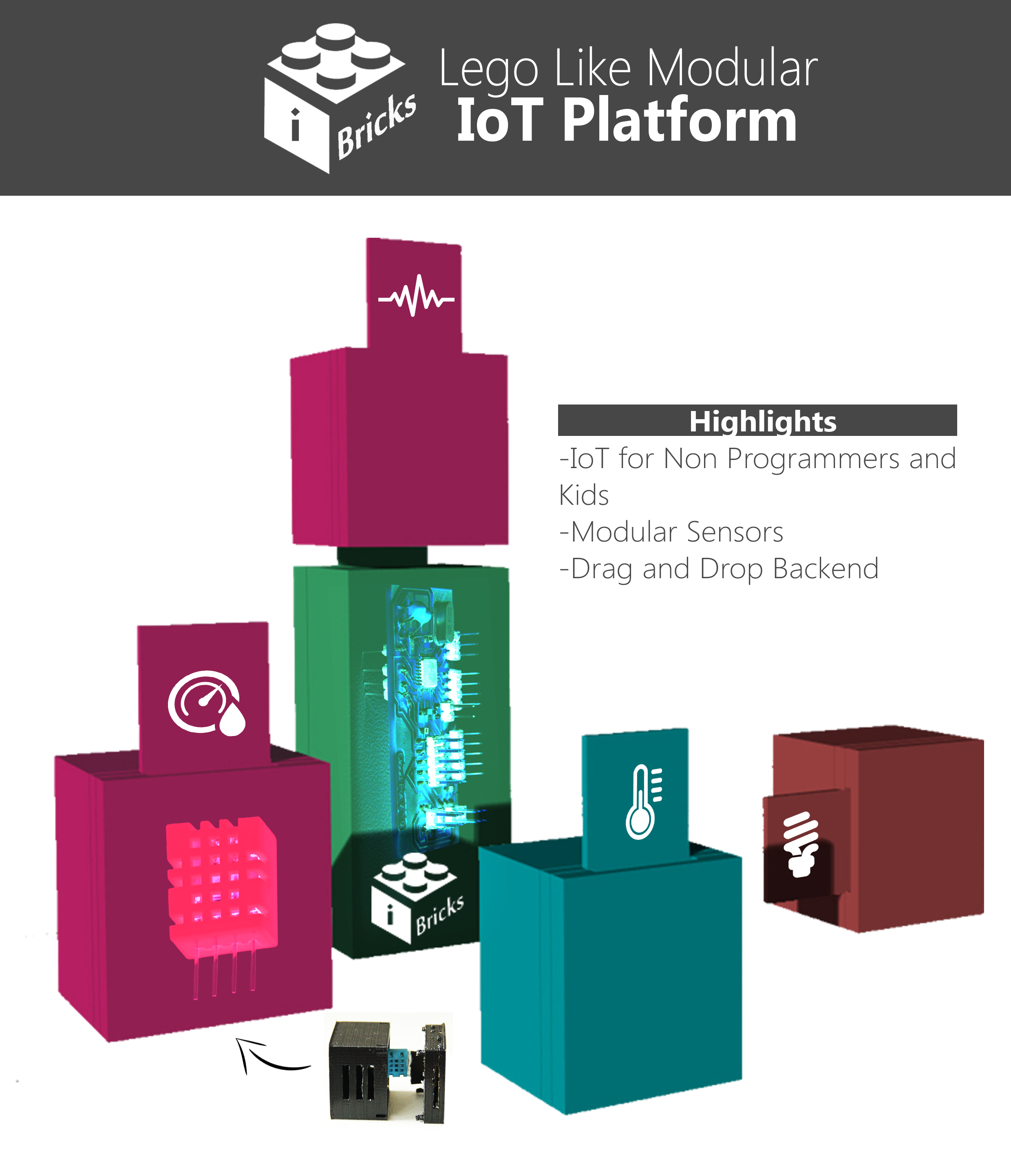
I-Bricks
This is a Lego-Like Modular Internet of Things(IoT) platform for Students and Non-Programmers , I am doing first part of this project as my Fab Academy Project ,after my course i want to make and publish this as a opensource platform .
 I-Bricks is a easy to use IoT sensors and actuators kit that can be control by drag and drop in backend ,No coding skills required ,technology interested and students can easily enjoy the pleassure of IoT they can customize and make their own things without pain.
I am doing cloudpot as a first phase of I-Bricks , I completed cloud pot sucesfully and started Modular design of I bricks in this documentation .
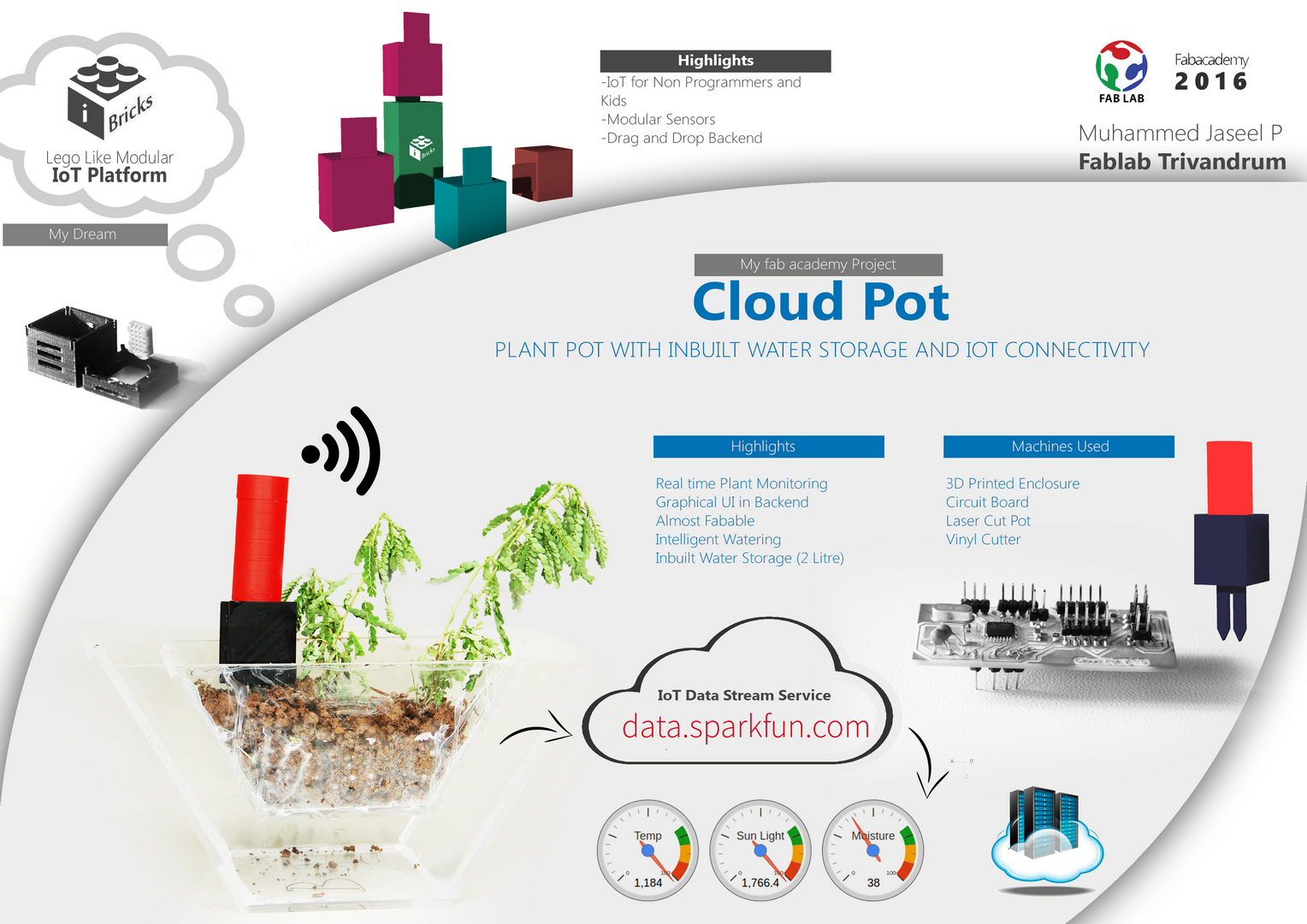
Cloudpot
This is a IoT Connected Plant Monitoring System which have inbuilt water storage facility and used for urben Gardening ,Indoor farming etc., My aim is want to make something interesting for my Fab Academy Project same time it should be suitable as my final project .
Features
1.Acess from anywhere
2.Inbuilt Water Tank (2 Litre Capacity)
3.Automatic Watering
4.Graphical Based GUI
5.Modular
Project Parts
Cloud Pot divided into three for project managemant and documentation .
1.Sensor Stick
1.1)Electronics Section
1.2)3D Designing and printing
2.Pot
2.1)2D and 3D Design
2.2)Laser Cutting of Acrylic
3.IoT
3.1)Sparkfun data stream
4.Webpage GUI
4.1)Graphical GUI in Webpage
How i fabricated ?
Here i am explaining how i made this project using digital fabrication.
1.Sensor Stick
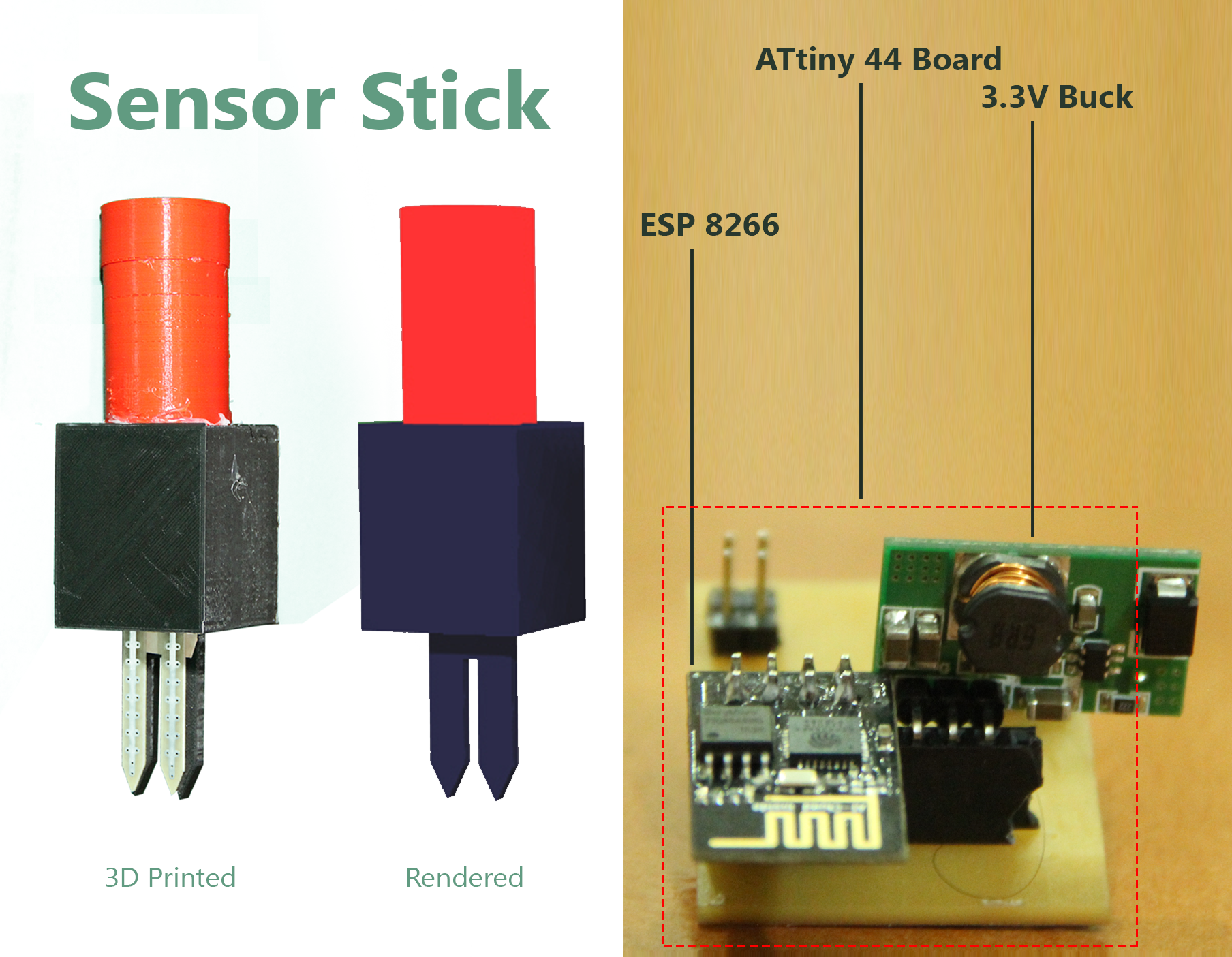
This is a important part in cloudpot ,i enclosed all sensors ,circuit boards,battery and ESP8266 in a single stick .
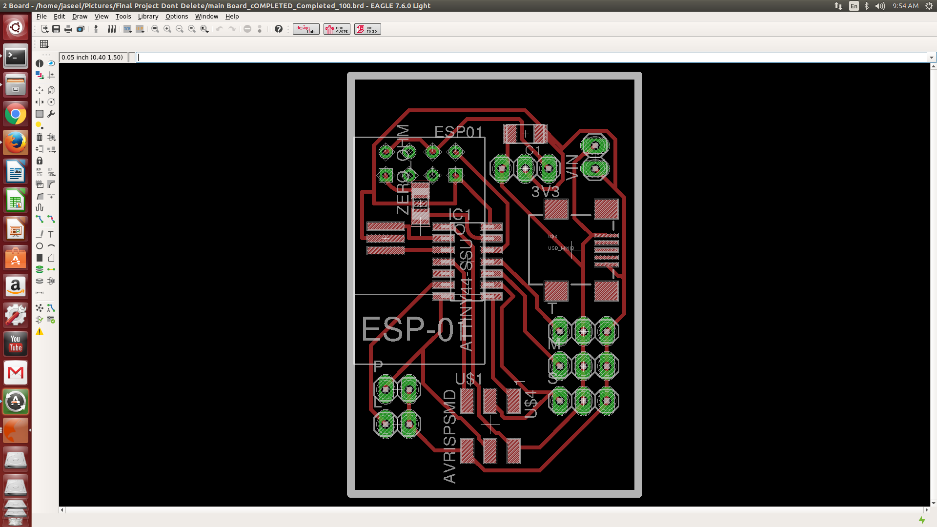
1.1)Electronics Section
First I designed ATtiny44 based board for sensors and ESP8266 but a problem occured , board when iam coding ESP8266 interfacing program in Arduino IDE it gives an eroor “Memmory Exceeded” because of that i am splitting my program into two microcontrollers ,I have option to upgrade my microcontroller to ATmega328 or any other higher Memmory controller but in this is a special case because i already using ESP8266 in my project which have two GPIO pins and programming facility. I am going to utilise that resource instead of making
1.1.1)Programming
Programmed ATtiny44 in Arduino IDE ,this is the code .
/*
 *Cloudpot - ATtiny44
 *
 *Muhammed Jaseel P
 *Fablab Trivandrum
 *
  */

#include <SoftwareSerial.h>
int mpin = 3;//Moisture sensor connected to PA3 of ATtiny44
int tpin = 2;//Temperature Sensor connected to PA2of ATtiny44
int lpin = 4;//Light Sensor connected to PA4 of ATtiny44
int Rx = 0;//TX of ESP8266
int Tx = 1;//RX of ESP8266
float moisture;
float light;
float temperature;

SoftwareSerial myesp(Rx,Tx);

void setup() {
myesp.begin(115200);
}

void loop() {

  moisture = analogRead(mpin);//read moisture
  light = analogRead(lpin);//read light
  temperature = analogRead(tpin);//read temperature
if(myesp.available() > 0){
    myesp.write(moisture);//send to ESP8266
    myesp.write("\n");
    delay(100);
     myesp.write(light);//send to ESP8266
    myesp.write("\n");
    delay(100);
     myesp.write(temperature);//send to ESP8266
    myesp.write("\n");
    delay(100);
    }
}1.1.2)ESP8266
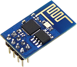
I am using ESP8266 module for aceesing wifi it have 2 GPIO pins and the main thing is it can program using Arduino IDE , I explained about ESP8266 testing and all in my Project documentation Page
1.1.2) 3.3 Volts Buck
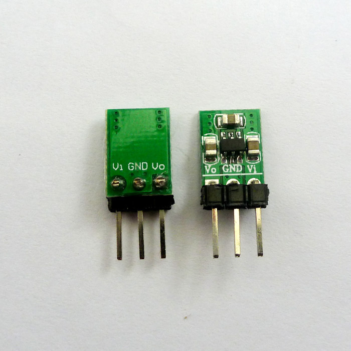
ESP works only in 3.3V logic for that we need a 5 Volt to 3.3 Converter for that iam using this buck in my project .
1.1.3)ESP programming
We can program ESP using arduino IDE + 3.3 Volt FTDI Cable , ATtiny44 sending sensor data serially to ESP ESP sends this data to cloud . Main Board Eagle File .brd
/*
 *Cloudpot - ESP8266
 *
 *Muhammed Jaseel P
 *Fablab Trivandrum
 *
  */

#include <ESP8266WiFi.h>

const char* ssid     = "SSID";//SSID of your Wireless Network
const char* password = "Password";//Password

const char* host = "data.sparkfun.com";
const char* publicKey = "[your public Key]";//key from data.sparkfun.com
const char* privateKey = "[your private key ]";//key from data.sparkfun.com


float moisture;
float light;
float temperature;
void setup() {
  Serial.begin(115200);
  WiFi.begin(ssid, password);//Connect Wifi

  while (WiFi.status() != WL_CONNECTED) {
    delay(500);
    Serial.print(".");//Connecting Indication
  }

  Serial.println("");
  Serial.println("WiFi connected"); //Sucess Message
  Serial.println("IP address: ");
  Serial.println(WiFi.localIP());
}

void loop() {

  while (Serial.available() > 0) //Checking status of sensor board
  {


  moisture = Serial.parseInt(); //for filtering datas from stream

    light = Serial.parseInt();

   temperature = Serial.parseInt();


  if (isnan(moisture) || isnan(light) || isnan(temperature)) {   // Check if any reads failed
    Serial.println("Failed to read  sensor!");
    return;
  }

  Serial.print("connecting to ");
  Serial.println(host);

  // Use WiFiClient class to create TCP connections
  WiFiClient client;
  const int httpPort = 80;
  if (!client.connect(host, httpPort)) {
    Serial.println("connection failed");
    return;
  }

  // We now create a URI for the request
  String url = "/input/";
  url += publicKey;
  url += "?private_key=";
  url += privateKey;
  url += "&temp=";
  url += temperature;
  url += "&light=";
  url += light;
  url += "&moist=";
  url += moisture;

  Serial.print("Requesting URL: ");
  Serial.println(url);

  // This will send the request to the server
  client.print(String("GET ") + url + " HTTP/1.1\r\n" +
               "Host: " + host + "\r\n" +
               "Connection: close\r\n\r\n");
  delay(10);

  // Read all the lines of the reply from server and print them to Serial
  while(client.available()){
    String line = client.readStringUntil('\r');
    Serial.print(line);
  }

  Serial.println();
  Serial.println("closing connection");
  delay(60000); // Send data every 1 minutes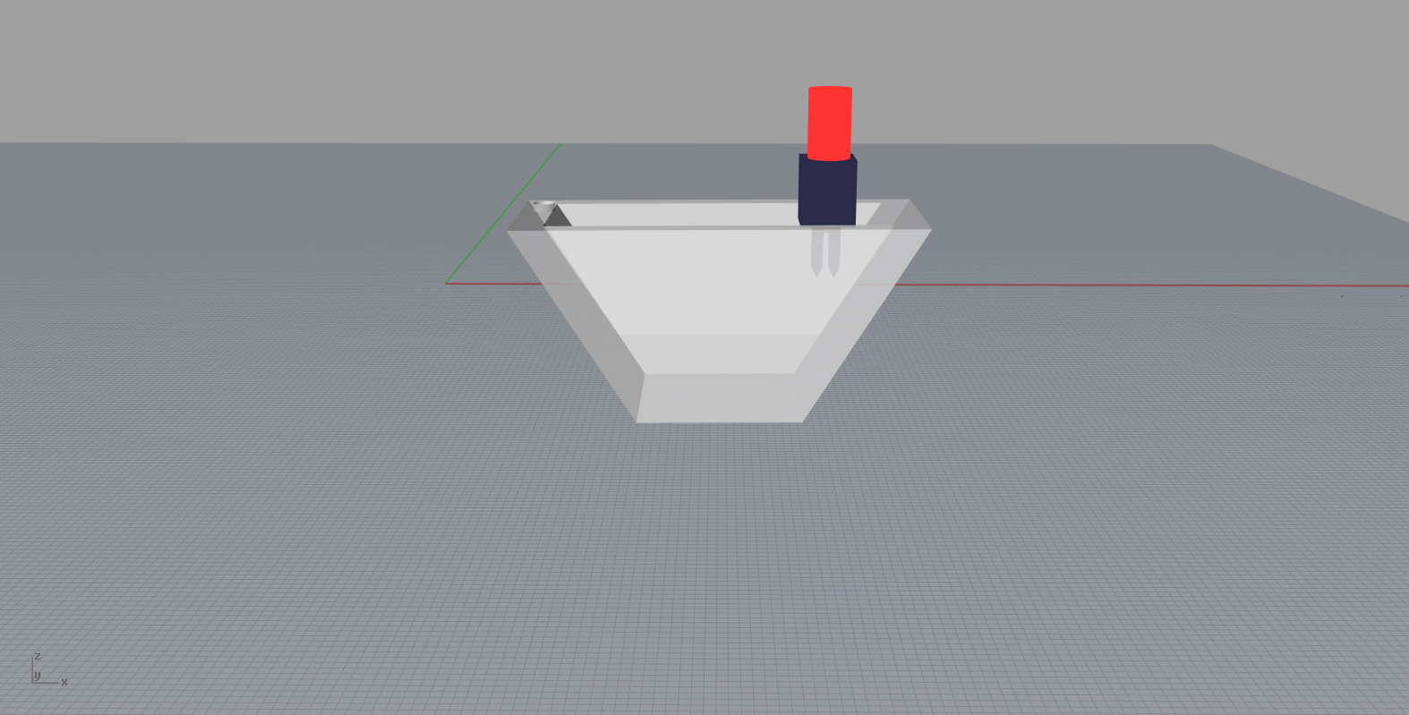
}1.2)3D Designing and Printing of Sensor Stick
I created a 3D design in Rhino after that i added some rendering works . after that i 3D printed this shape in Ultimaker already explained about Rhino Designing and 3D printing in my 3D Scanning and Printing week

2.Pot
I fabricated a pot in acrylic using laser cuttter and used rhino for designing .
Download Rhino Design File of Pot
I explained about laser cut in my Computer Controlled Cutting Week
3.IoT
In this part iam configuring and storing data stream in cloud,after literature survey i decided to do using Sparkfun’s Free Data Stream
3.1)ESP8266 sends data to a specific url as a data stream i am using Sparkfun’s Free Data Stream for that purpose it is simple i will explain in next session .
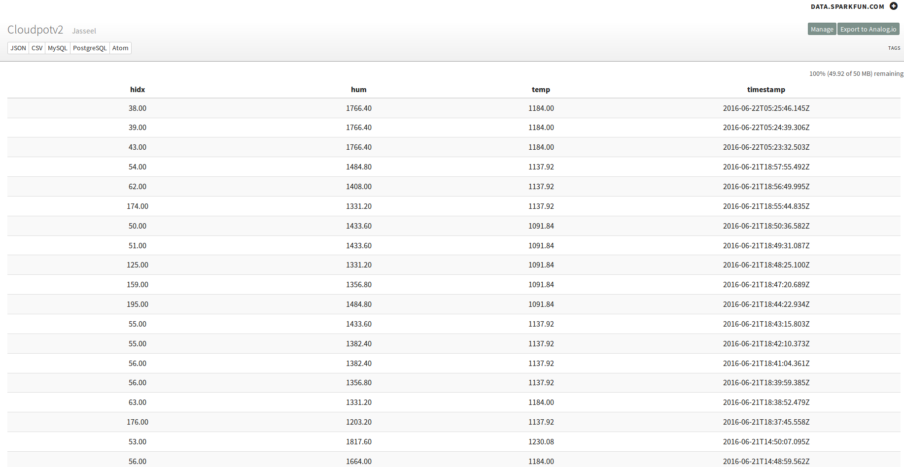
3.2)Sparkfun’s Datastream

It is a simple and free data stream serviece without any registration or Sign-up , it supports diffrent data parsing techniques like JSON,CSV,MySql etc.. I am using JSON .
Steps
Go to https://data.sparkfun.com/ and Click “Create”
Give Name,Description,Fields(Temperature,Moisture,Light etc ) and alias
After finishing the above step you will get two keys public_key and private_key save this keys
HTTP GET request for sending data looks like this,
data.sparkfun.com/input/YOUR_PUBLIC_KEY?private_key=YOUR_PRIVATE_KEY&temp=82.04&hum=53.10&hidx=83.29
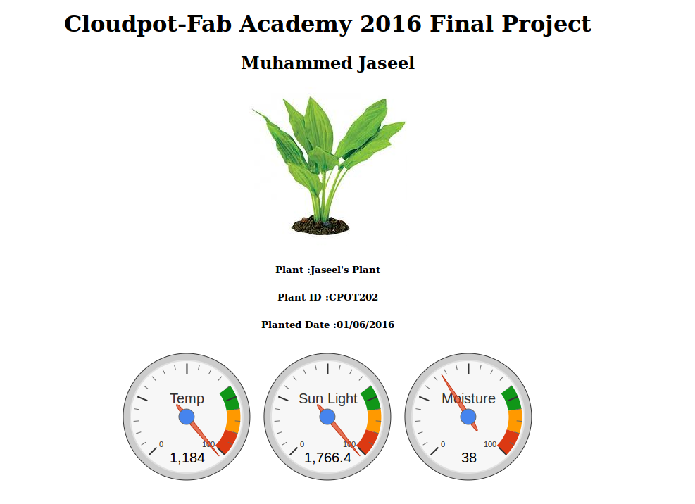
4.GUI in Webpage
I am parsing JSON data from data.sparkfun.com to my Fab Academy Archieve using Google Chart API , it converts JSON to a graphical representation .
Bill of Materials
What I Learned
I learned IoT interfacing ,3D Designing and rendering.
Problem Faced
I spent 1 week to solve ESP8266 Interfacing problems.
Downloads
Stick
Pot
Download Rhino Design File of Pot
Bill of Materials]
Whats Next ?