
COMPUTER CONTROLLED MACHINING
This week is dedicated for computer controlled machining. As part of learning how to make some thing big using computer controlled machining, I thought to convert my workbench at home to a complete test bench.
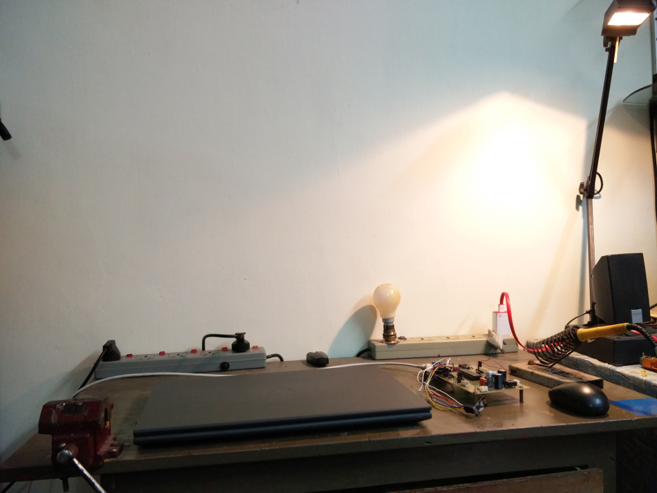
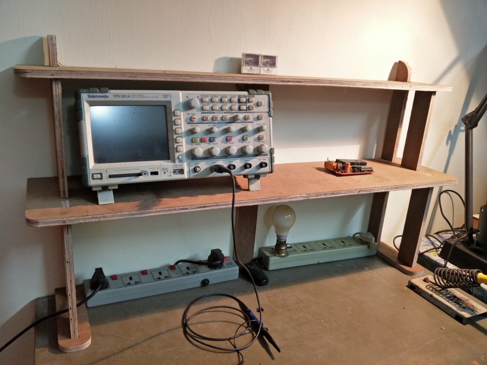
This is the work bench I have for doing my experiments. It becomes difficult as I use my test instrumentens while working here as the space is much limited. So I thought to add rack like structure to this so that I can stack the oscilloscopes, test jigs and other debugging tools.
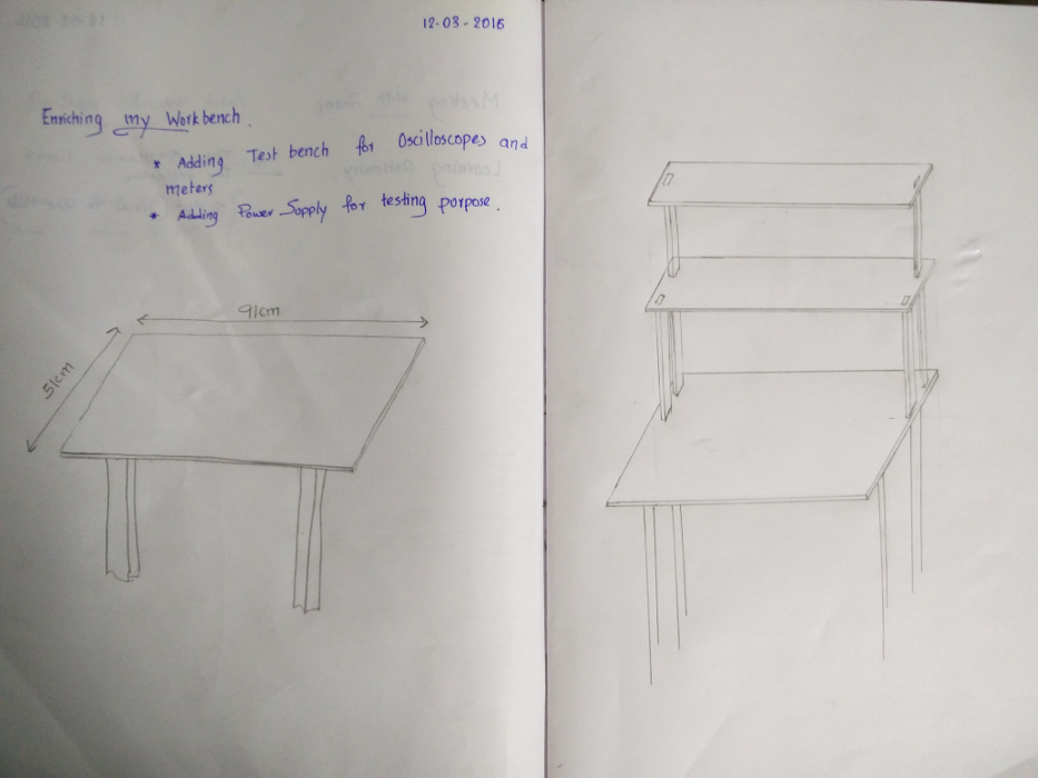
This is the rough sketch I have in mind to make..
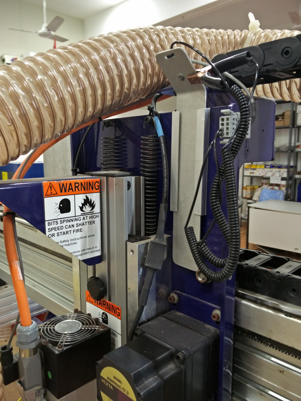
SHOPBOT IN OUR FABLAB
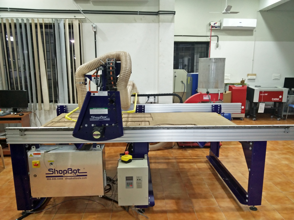
This is the shobot we have in our lab, This has a bed dimension of 8*4 Feet space.
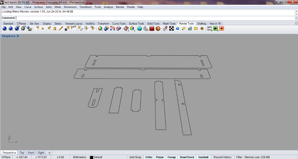
The first thing to make my test bench was to get the drawing ready, it was done in Rhino
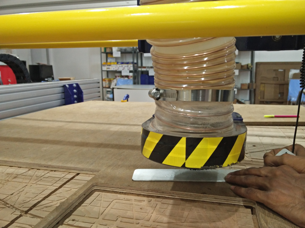
FIXING THE MATERIAL TO BE CUT
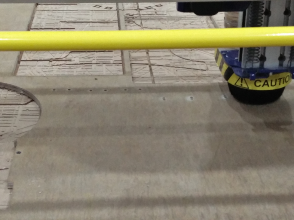
The wood we plan to cut should be tightly fixed to the bed of shopbot on top of the sacrificial layer as shown.
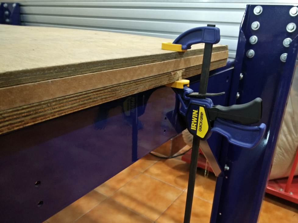
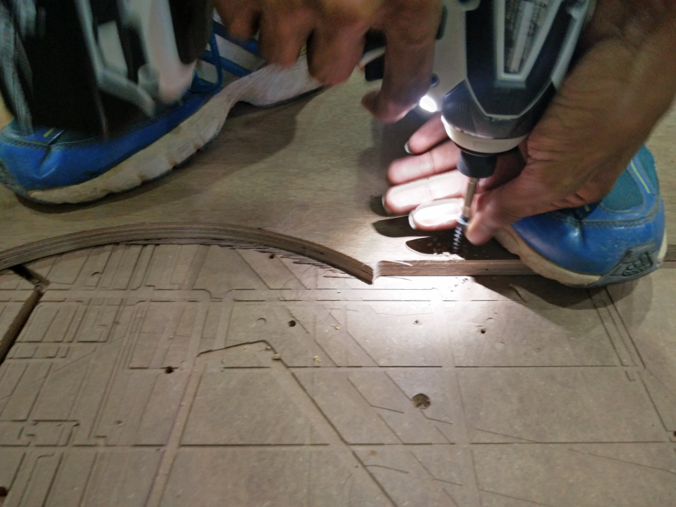
As I was planning to use the remaining material which was already cut before, some of the portions had curves, this has to be tightly screwed to the bed to keep them fixed as shown..
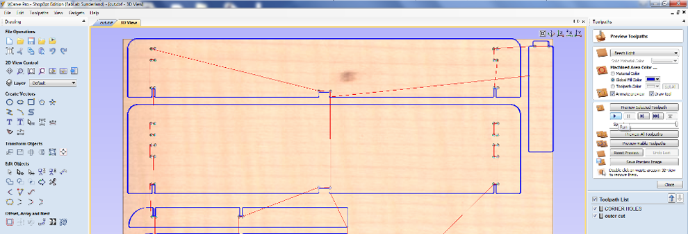
Moving on to the software part, The design file made in Rhino and is exported as .dxf file. This is to make the g-code which will be finally send to the CNC Machine. We use the software "VCarve" for this.
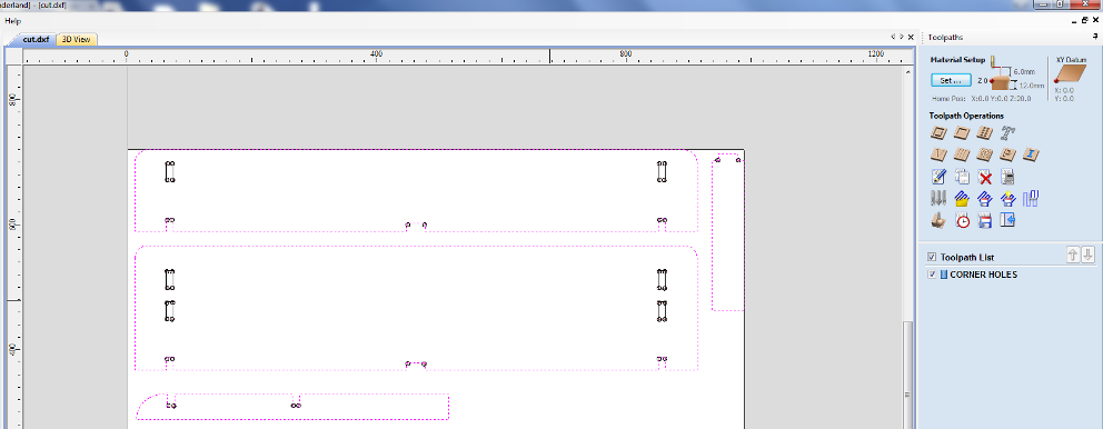
Step1 is to import the .dxf file to Vcarve.The software automatically chooses the bedsizes, which can also be changed optionally.
Step2 is to go to Material Select
Step3 - XY Datum Position
Now clicking OK takes you to the New window with all the other options.
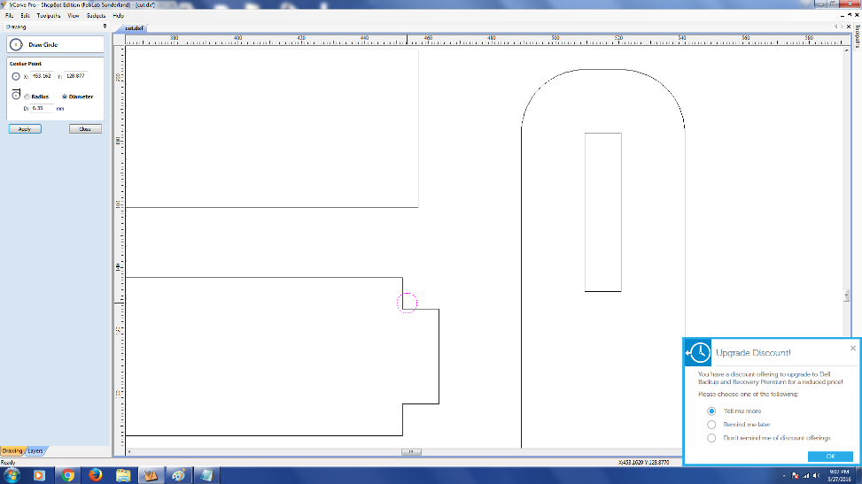
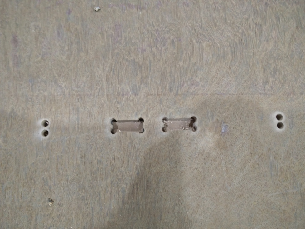
Shopbot's bit is round and it goes outside of the line we have drwan to be cut so cananot get a 90 degree cut. Insted there will be an arc formation as you observe. To overcome the difficulty so caused, we have to put some holes in corners (which lies inwards , where the material needs to be removed ) as shown below.

Select all lines and check whether there are any multiple lines, also check if the drawing is a closed loop..
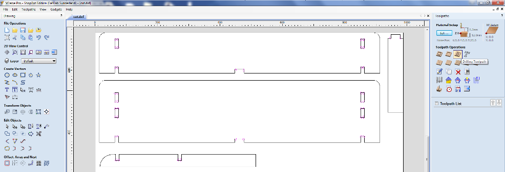
Now select all the circles and go to toolpath
Cut depth - 13mm
Tool - 1/4 Inch
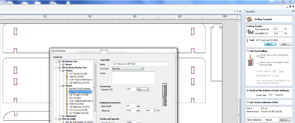
Now goto Tool Database
Spindle Speed - 1200RPM
Feedrate - 35
Select the option Calculate after giving an appropriate name.
Similarly for Cutting EDGES,
Select bit, Select where to cut --> Outside/Right , Inside/left , we select the first
Give Name --> Outercut --> Give calculate
Select bit, Select inside
Give Name --> Outercut --> Give calculate
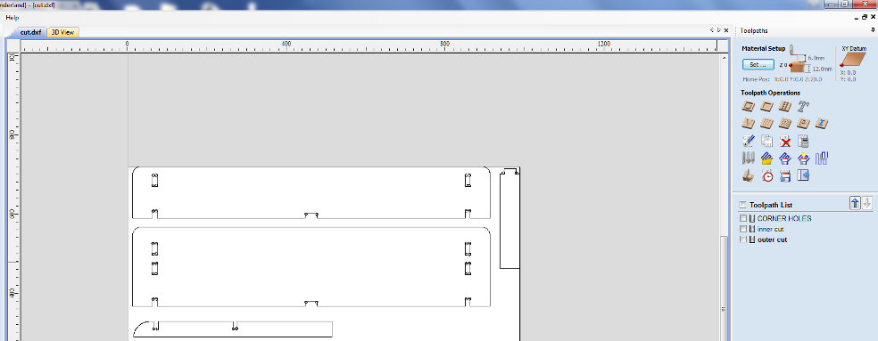
SELECT THE ORDER in which the cutss are to be made,
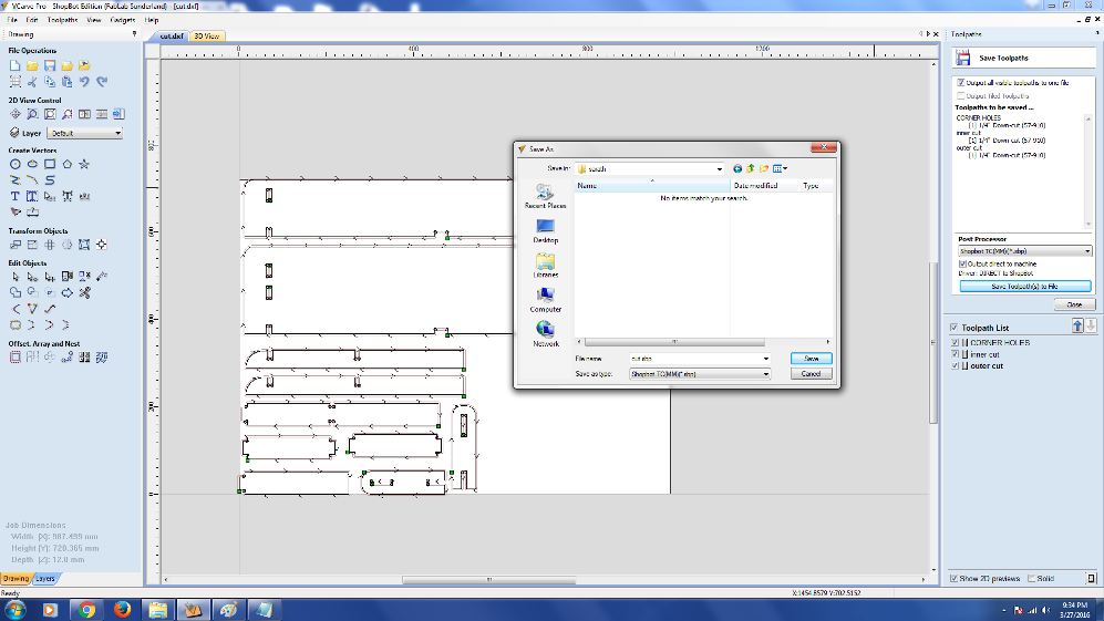
Verify once again if all the cuts to be made are selected and save this toolpath. This creates a .sbp File
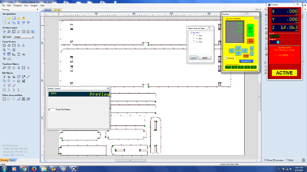
MOVING ON TO SHOPBOT
Open the Shopbot3 Softwre
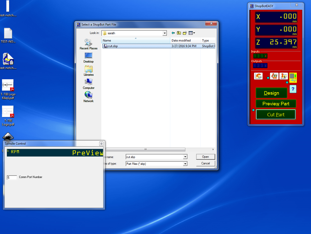
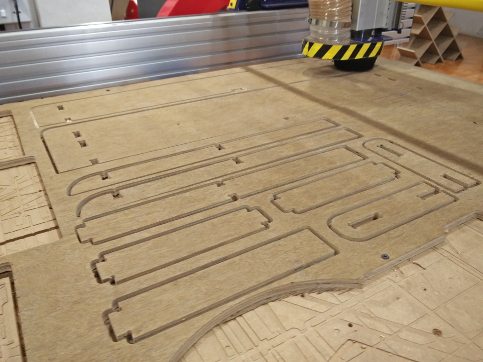
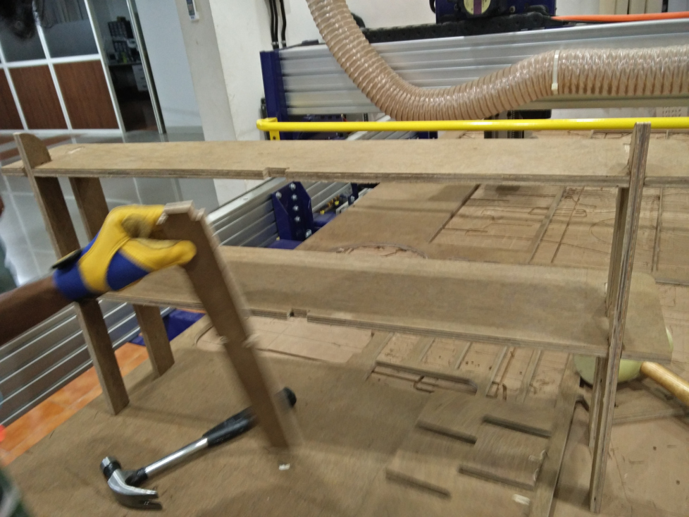
As we selected order, the holes are first cut by shopbot..
Then it starts the inner cuts..
Finally the outer cuts..
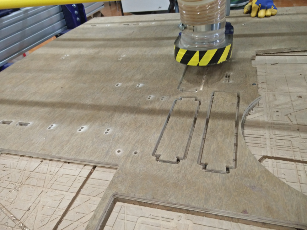
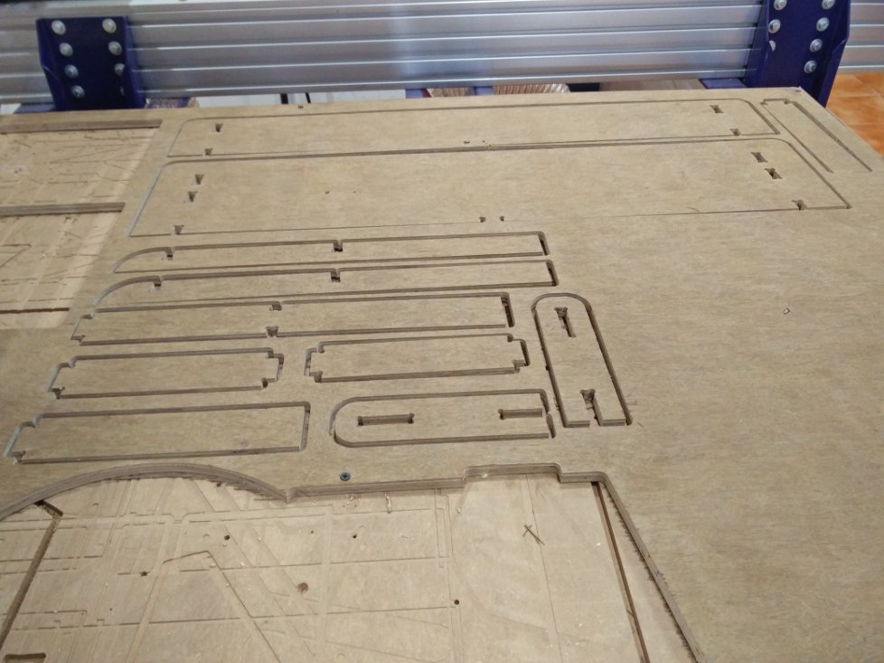
About to finish the cutting..
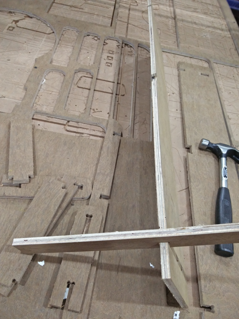
Completed the cutting..
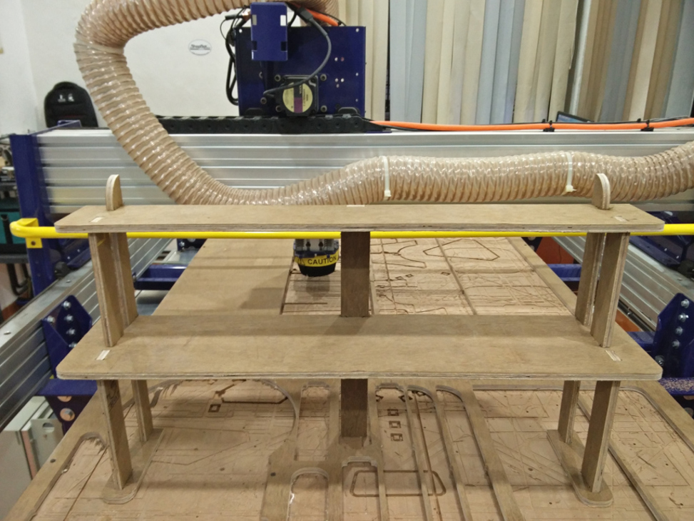
Now its time to start fixing them together..
Thanks to Yadu for his help in fixing them..
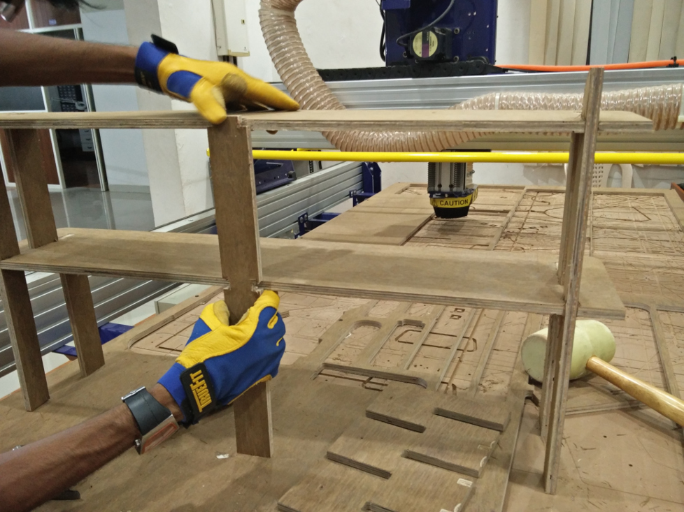
Almost done, getting it to the shape we thought of..
The design files can be downloaded from here.