
Final Project
Turntable Device for 360 Degree Photography
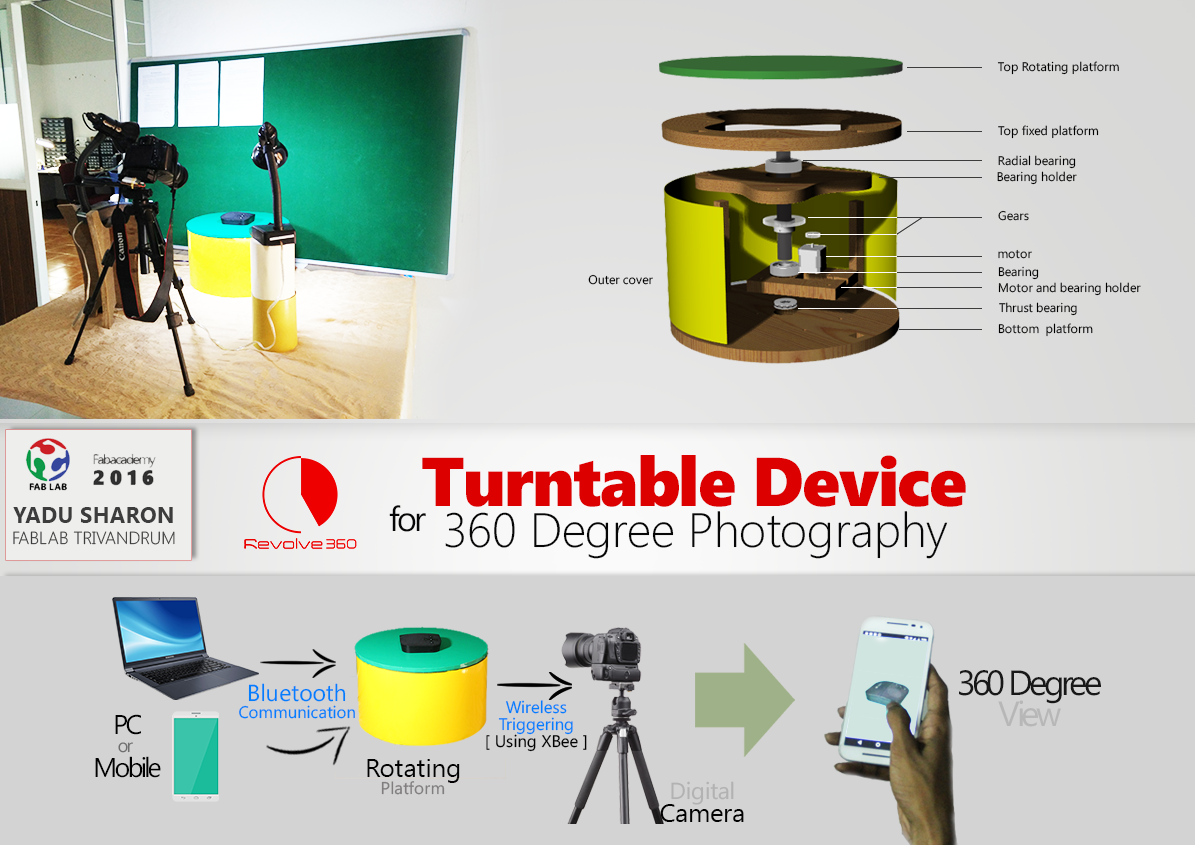
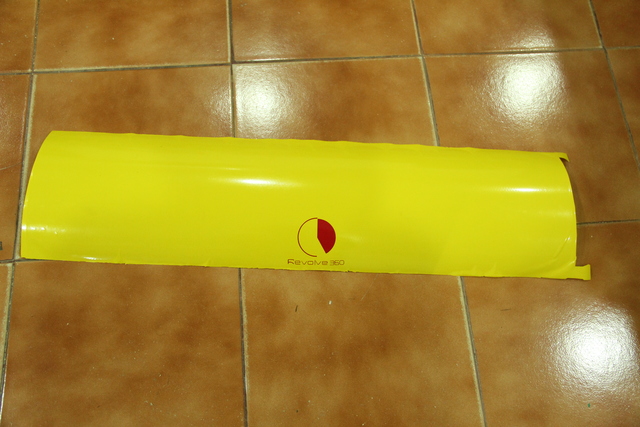
My project is to make a device which helps for 360 degree product photography. I named it as "Revolve 360". It has many useful applications in 3D imaging, e-comerce websites etc. The below poster will give an over all idea about my project.
I have proposed the idea in the first week of fab academy and I had made a rough sketch of the project. For making a 360 degree view of a product, the product will be placed on the device which will rotate by fixed angles and the camera is kept stationary. The platform will get rotated by a fixed angle and will wait for a while for capturing the image of that instant. This process will continue till the total angle becomes 360 degree. So by merging all the images captured, we can make a 360 degree visual of the product.
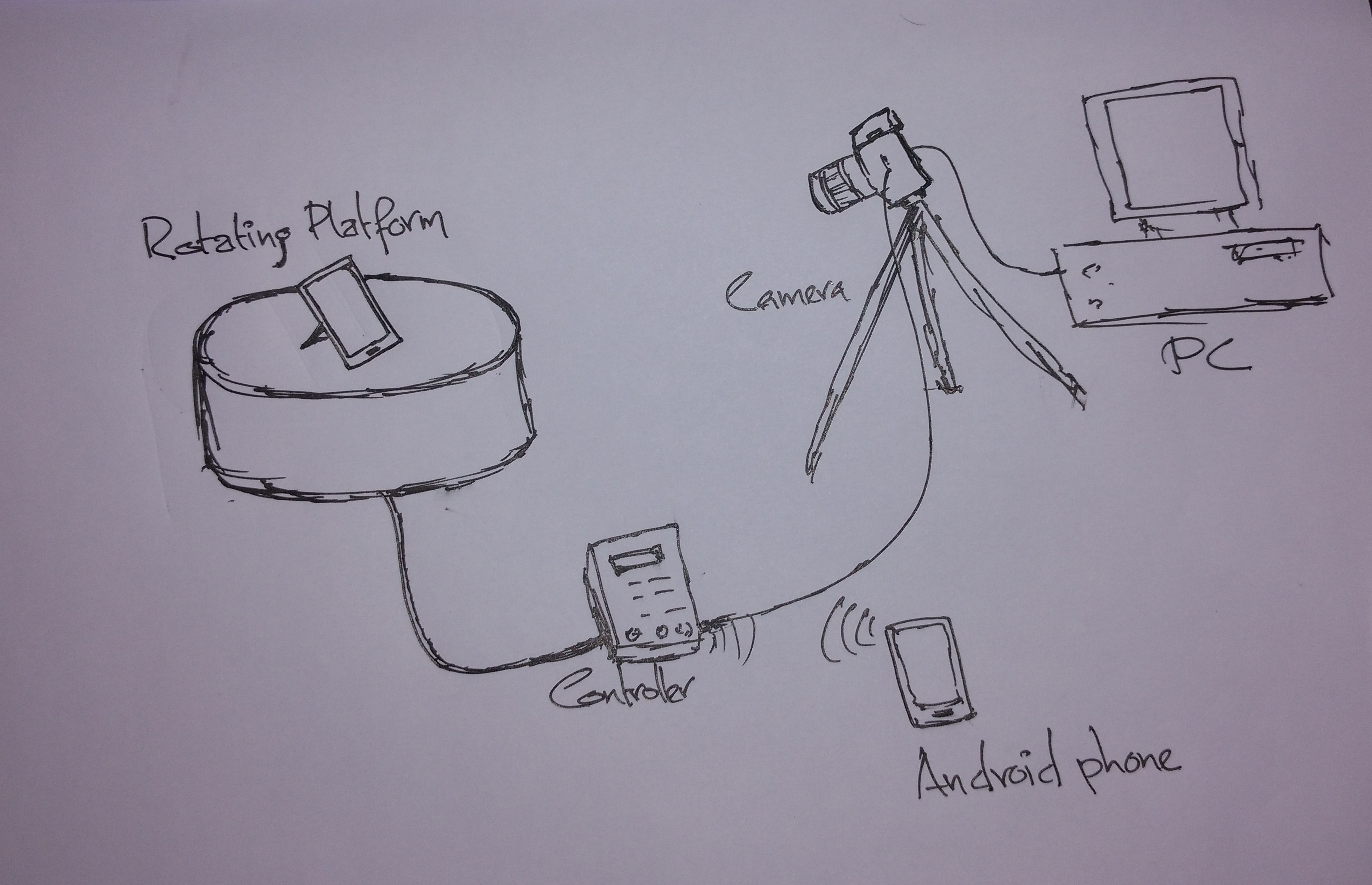
Rough sketch of my project
The processes I have gone through are :
Design
I have made some CAD design in the week of Computer Aided Design itself. But it doesn't have proper dimensions and can't be used for machining and cutting. Here is the link for Computer Aided Design week.
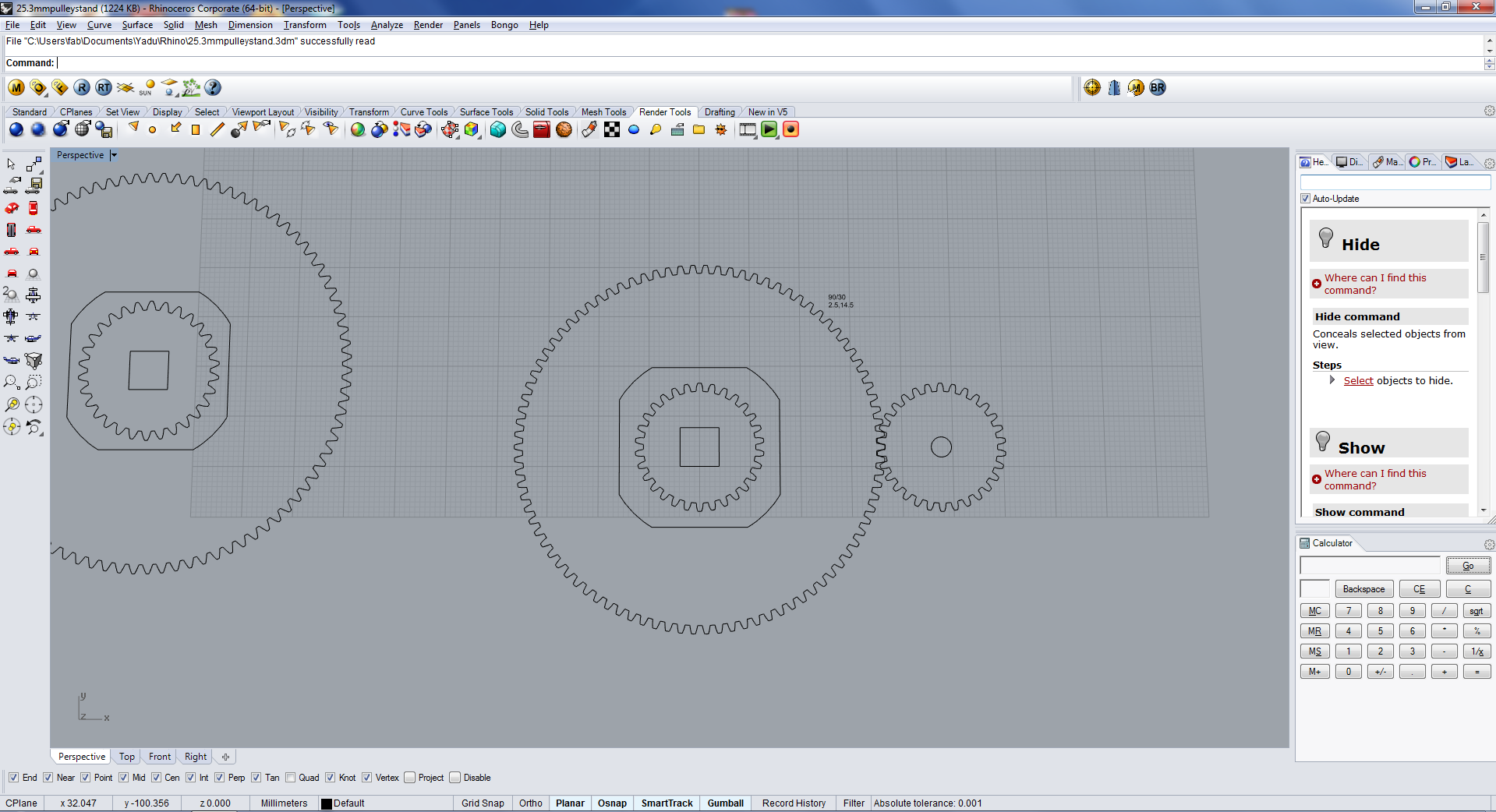
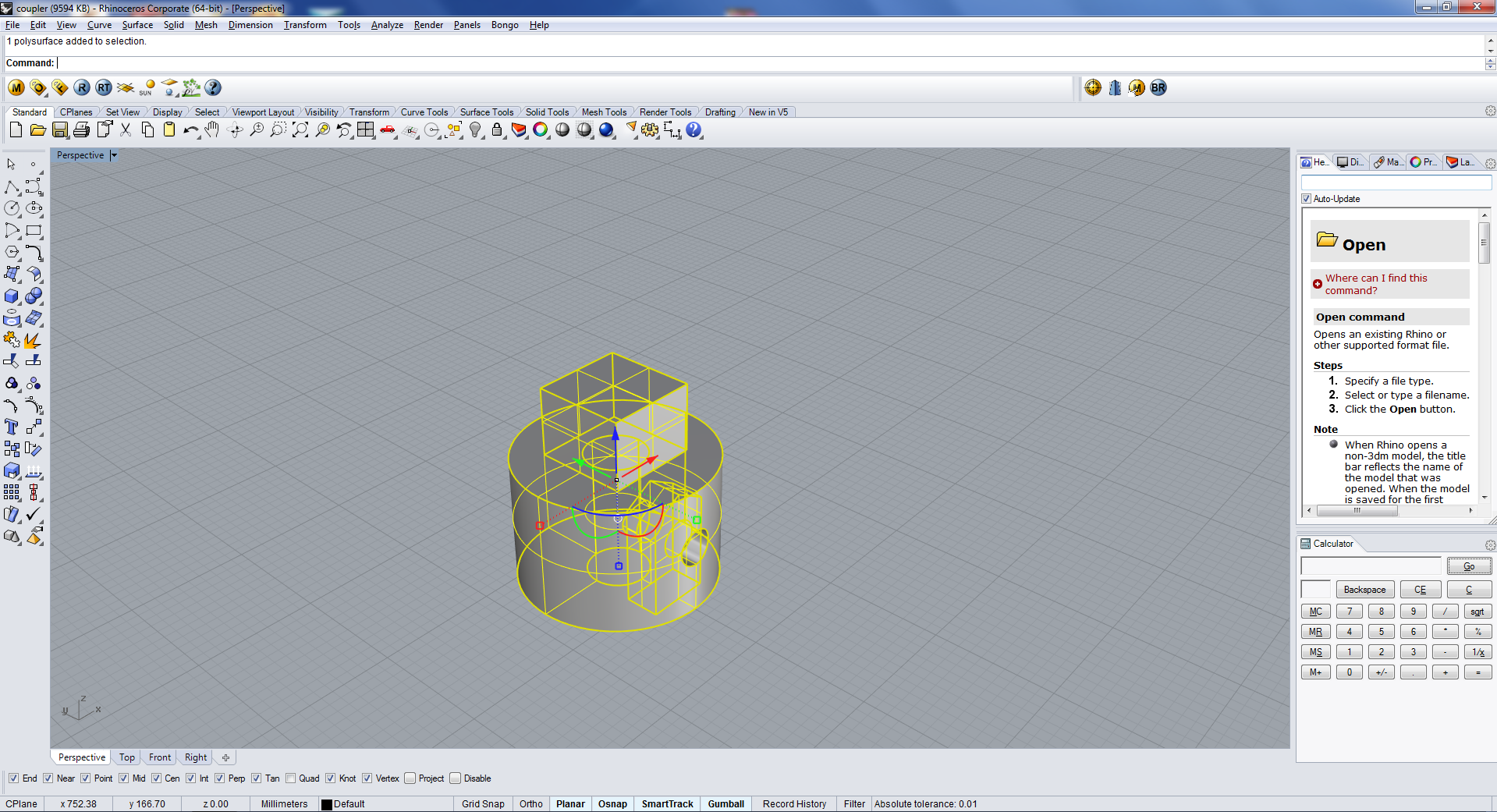
I used rhino for the CAD works. I usually use rhino for designing.
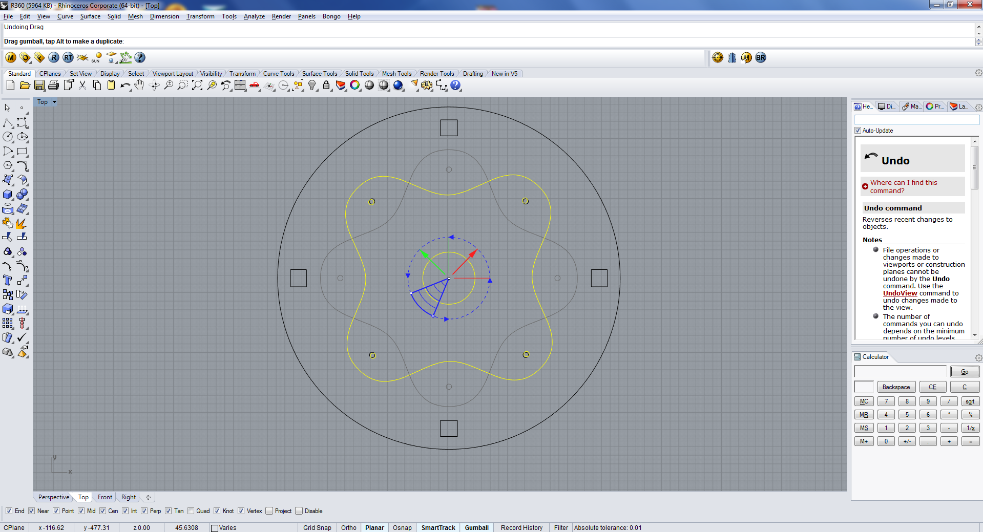
Here are some screens shots of the design. It is dificult to take too many screenshots while working, so some are here.2D design of bottom plates
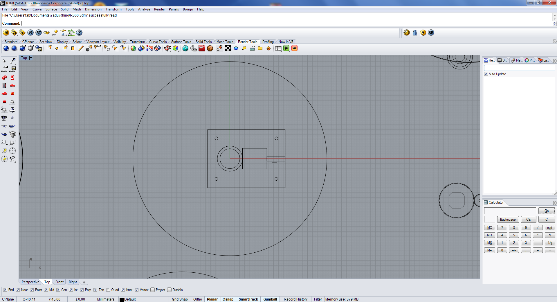
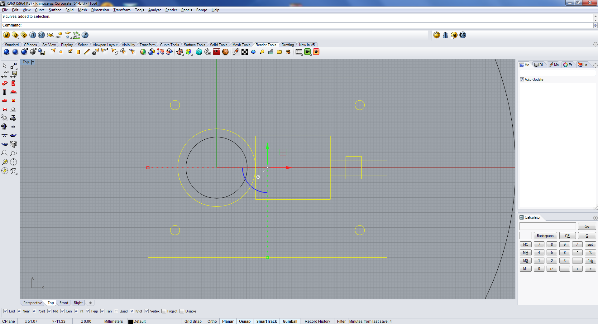
2D design of bottom plates

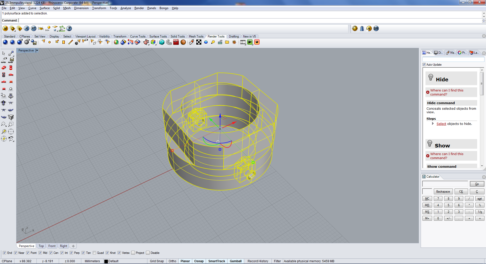
See all the parts in 3D here
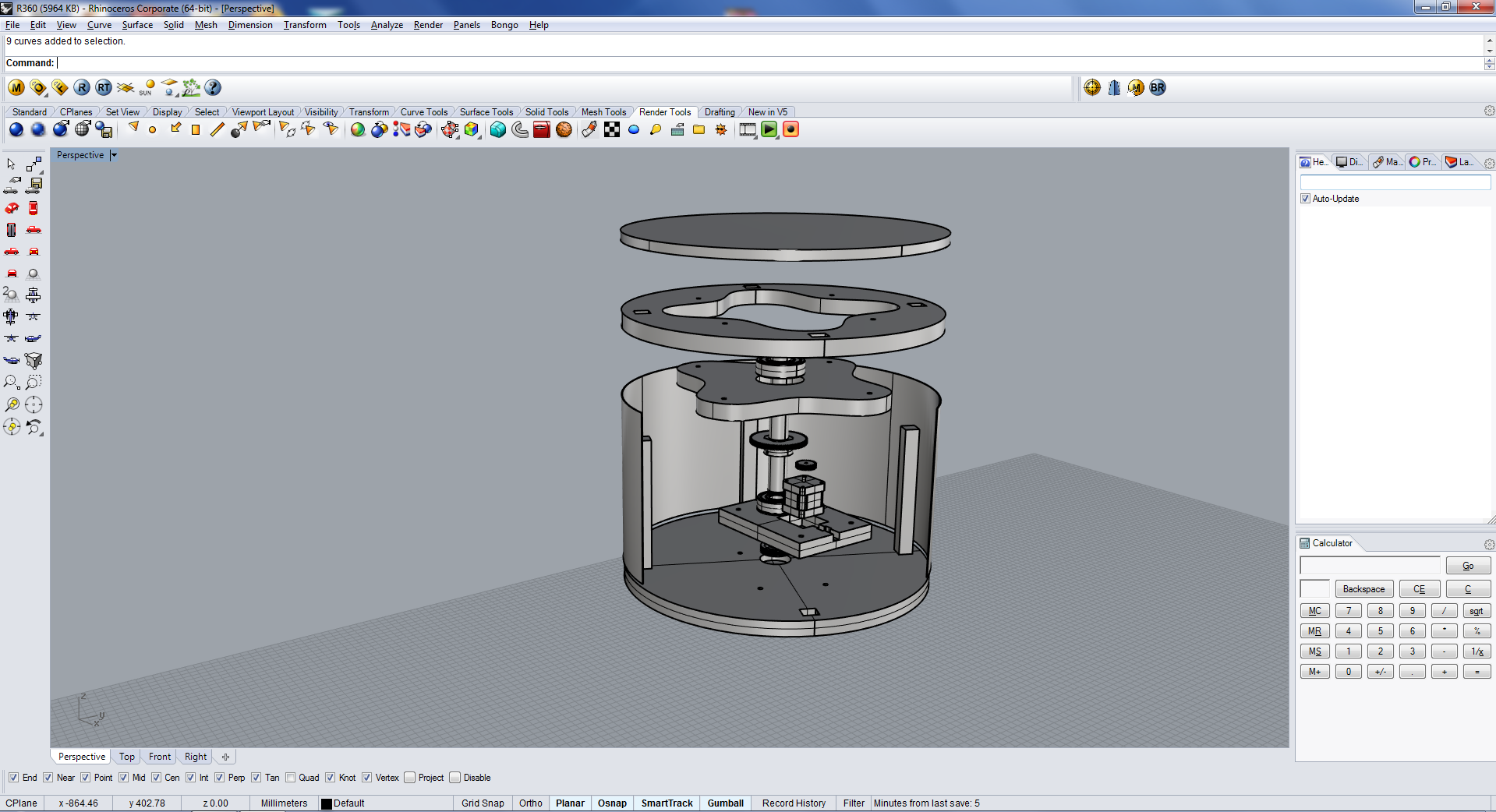
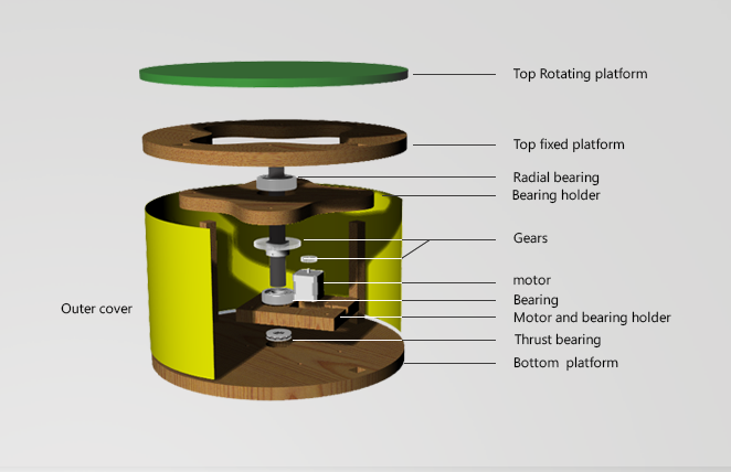
I have labeled the parts for easy understanding.
Download the design files
Building the hardware
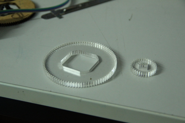
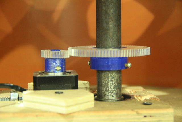
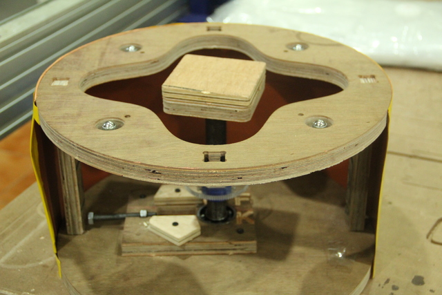
Most of the parts are made from plywood using shopbot. Some are 3D printed and some gears are made using laser cutter from acrylic sheet.
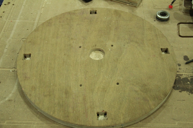
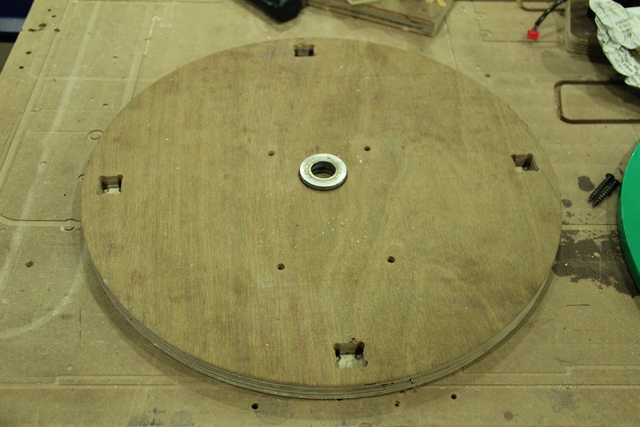
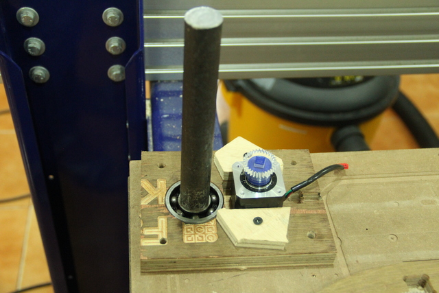
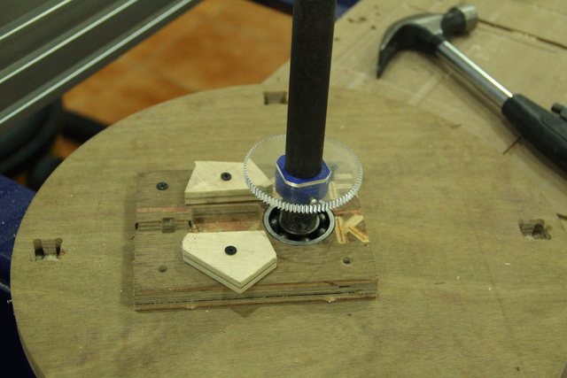
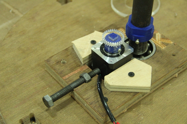
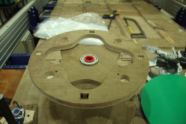
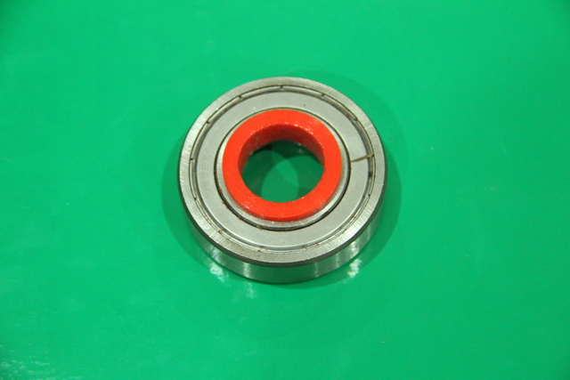
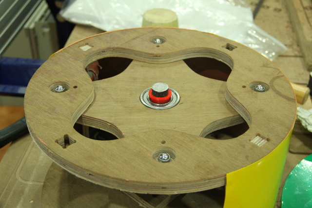
I have labeled the various parts of my device just before , so now you can understand the below pictures easily. First is the bottom most platform. It has a slot for the thrust bearing. I use this thrust bearing inorder to withshtand much weight.
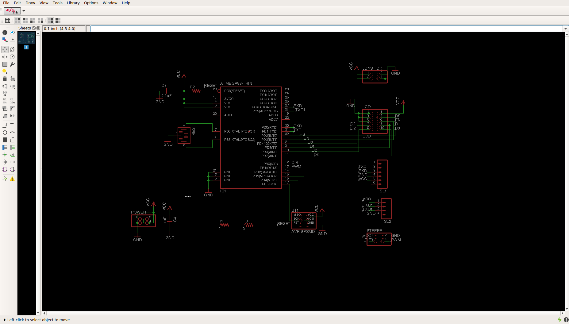
The controller
For making the controller part, I have gone through three processes, electronics design, electronics production and embedded programming. The micro controller I am using is Atmega 328. The programming language I chose is C . Since I have to control the stepper motor , I have made a small separate board for stepper drivee controller. So total I have a main board and a stepper controller board. In the main ports I have put some ports for following connectionsHere LCD and joystick are optional. Since we can communicate via bluetooth with the help of an android phone or laptop, LCD and joystick can be avoided. But I have put connections for the following because for controlling without a laptop(or PC) they are necessary.
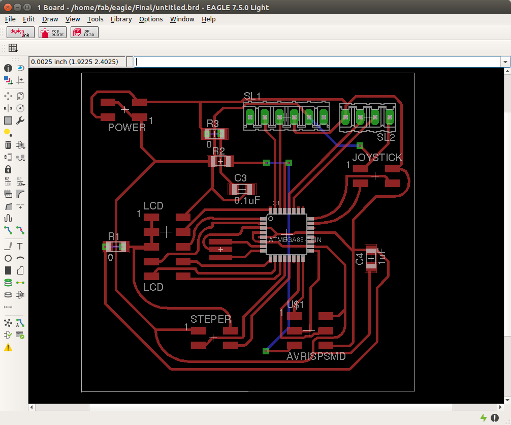
This is the design for main controller.
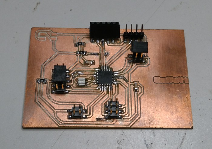
Soldered the components
I designed another board for stepper driver. I use Pololu A4988 for controlling stepper motor. So I designed the board with some female connectors so that i can plug the A4988 stepper driver in to that. Note that the schematic is not correct as per the labels, but I used the pin so that I can plug the A988 from bottom side of the board. Anyway the board design will be okay
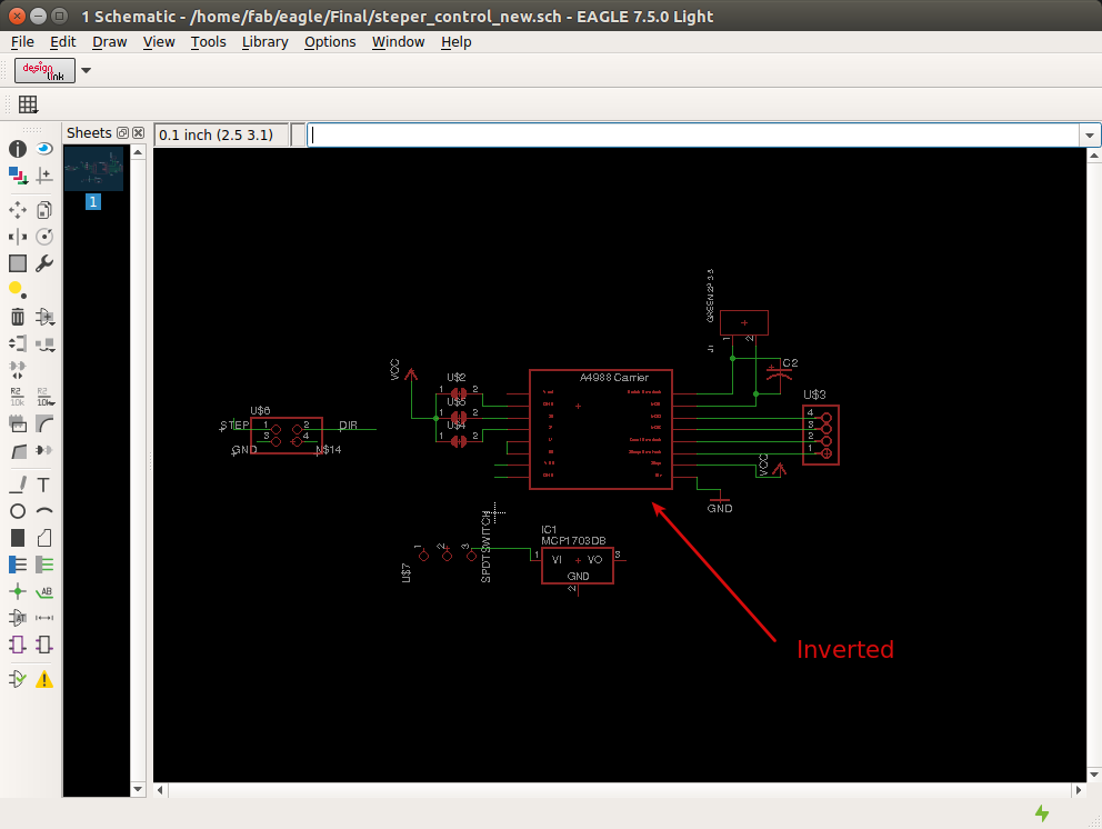
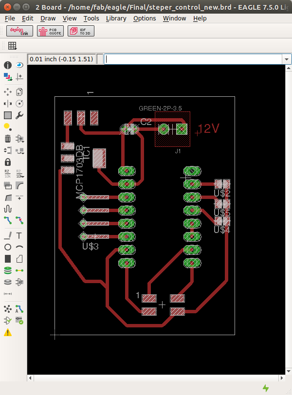
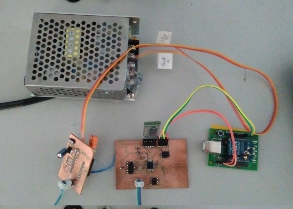
Note that i have included the voltage regulator in board. For driving the motor we need 12V. So my plan is to make a 5V from the 12V and the same can be used for main board also since the vcc and gnd are same. Anyway i have put a switch, if we want to power the micro controller externally the switch will be usefull.
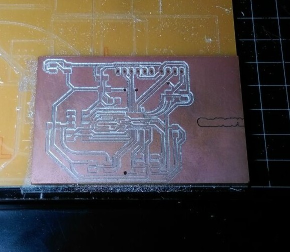
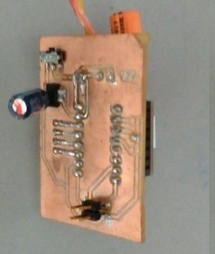
I milled the board and soldered the components.
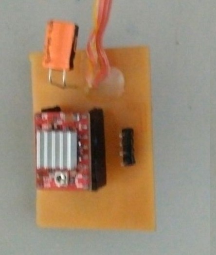
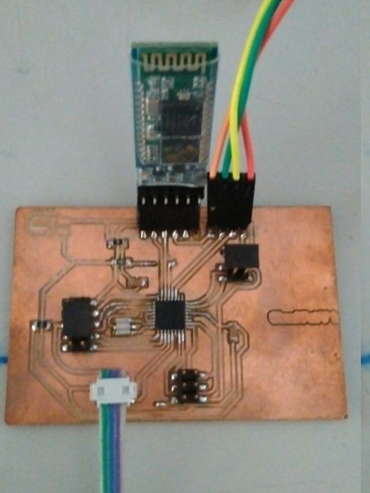
All parts are connected together.
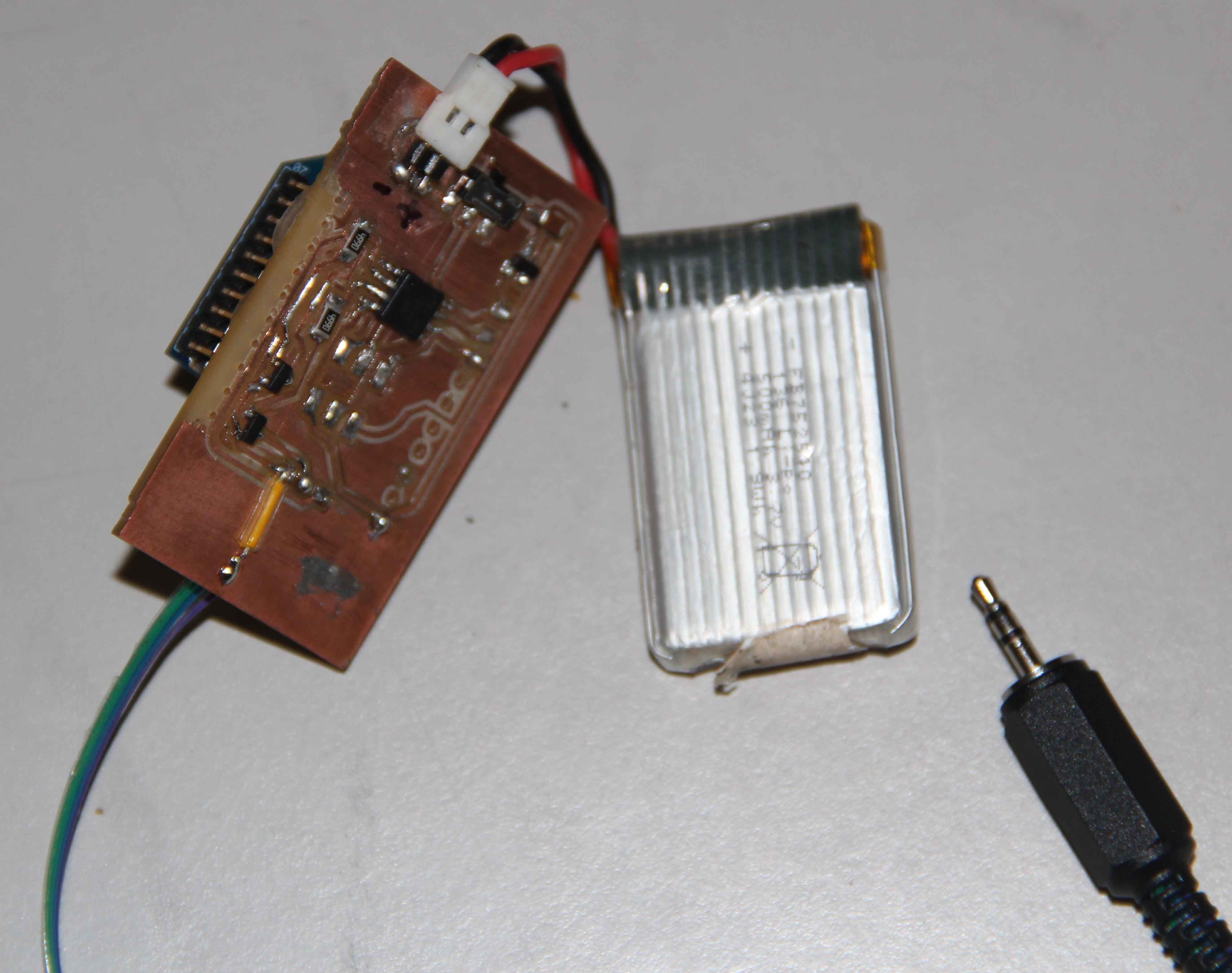
Camera remote
I need a remote for trigerring the camera. It can be wired or wireless actually but i chose wireless. I have already made the remote in the networking week.Here is the link for networking week
Programming
The programming labguage i used is C. I already explained what my device to do is rotate for a fixed angle, triger camera , whait for a while and continue this procedure. For this the controller has to know many parameters like
The packet is lik
$R360<Total angle><Number of snaps to take><Delay time><Direction>
I can explain one by oneTotal angle
This is the total angle in degree. Usually it is 360 for 360 degree photography. If you dont want 360 degree but only 180, then you can give 180 there. It must be in degrees and should have 3 characters.
Number of snaps
This is the total number of snaps you want to take. It should be in two digit.
Delay time
This is the time delay for the controller to wait for camera click. I put this option because when the shutter speed of the camera is varied extremely the delay time should also be changed. This should be also in two digit.
For example if it is 1 Second the digit to send is 10. If its 1.5 second then it is 15. This is the format.
Direction
This is for which direction it has to rotate, if it is clockwise then the character to be sent is C, and if it is anticlockwise send A.
An example Here is an example. If we want a 360degree visual with 30 snaps with 1s time delay with rotation in clockwise direction, then the packet to send is
$R3603603010C
Right now i send this using a serial terminal. But my plan is to make a GUI which will take all the parameters as input , it will make the packet from the parameters and will send it over bluetooth.Here is the code written in C for my controller
Final Product
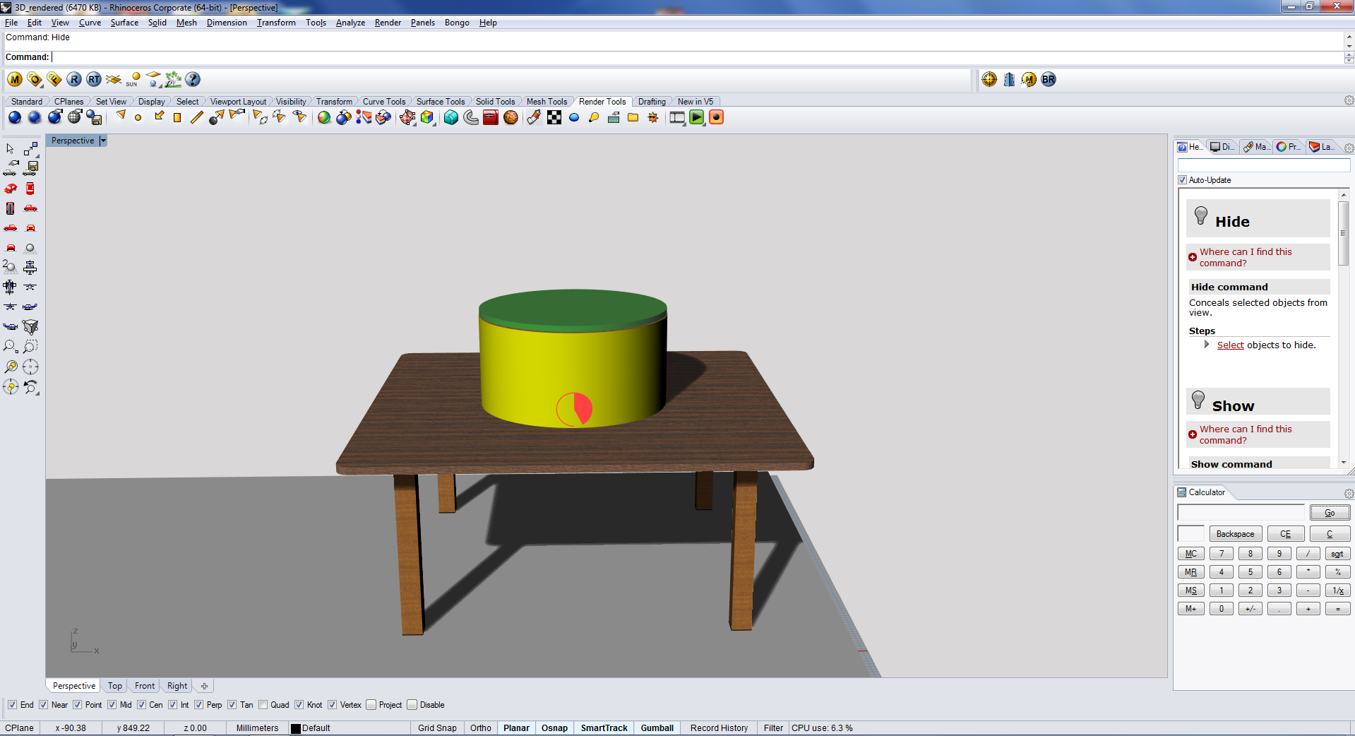
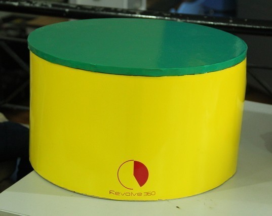
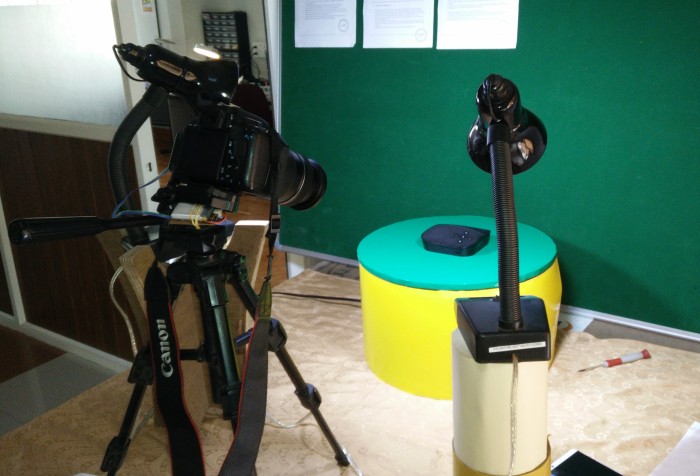
Putting all together i made it working. See the hero shot of my device with a product placed on it.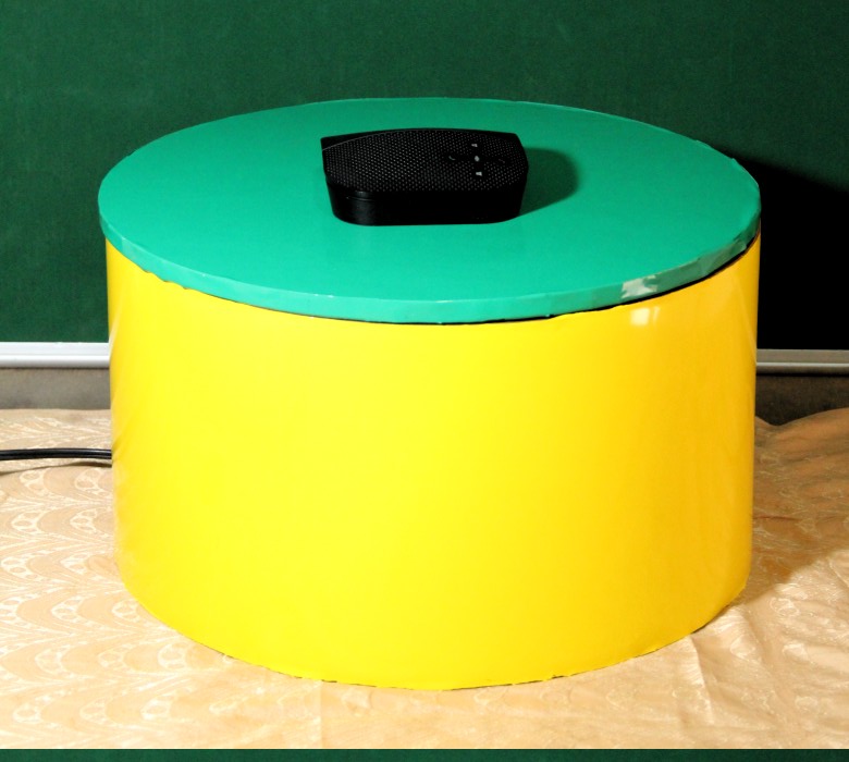
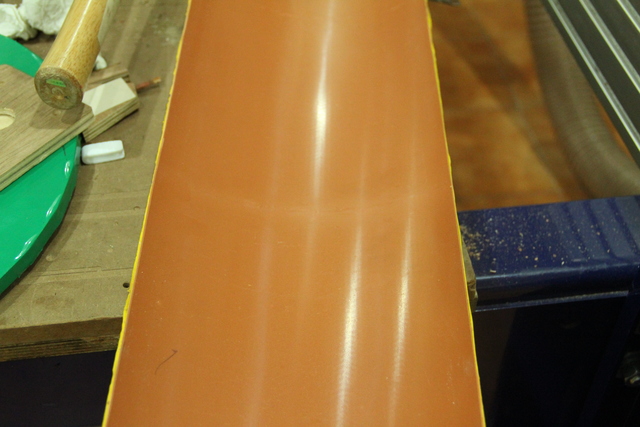
I made a setup with some lamps and lights for the image capyuring. Settingthe light without shadow was bit difficult for me. I could n't make it properly actually.
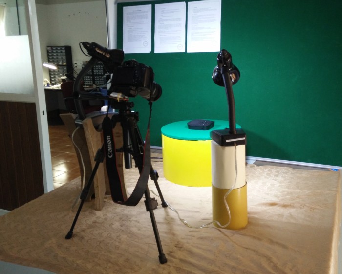
Now see the video to know how it works.
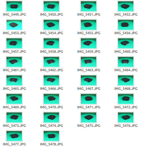
Now we will get a lot of pictures (here in this case, it is 30). Here it has a green background we can remove it using photoshop, but i dint do it now. The best idea is to chose a white colour platform and background. We dont have a white vinyl sheet, that is why i used green.
Click and drag