Week 3 Day2
From line 5593 onwards where
"#define board " starts we can change the parameters like width of line,
board width and length etc.
Machining
Machining parameter
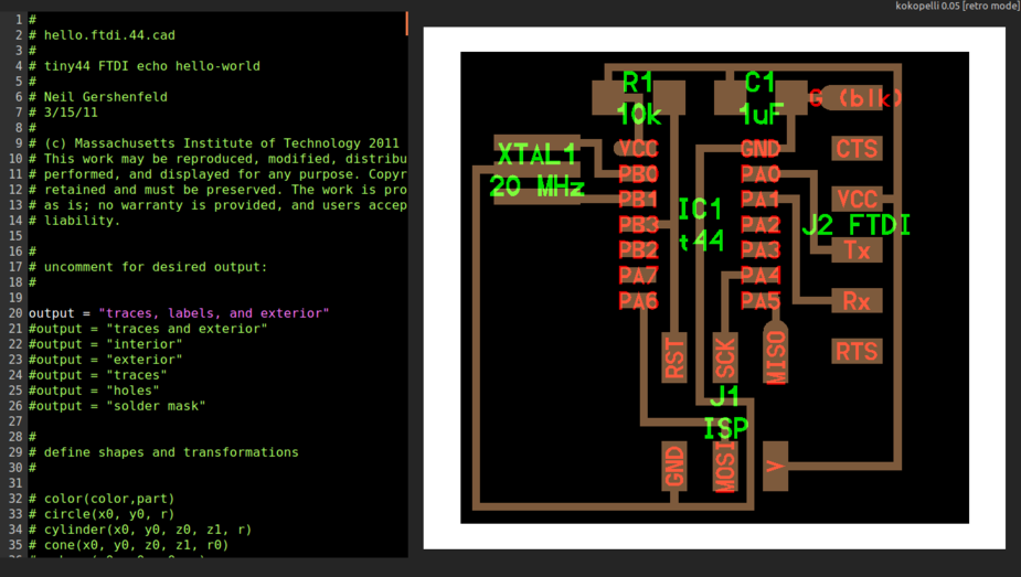
Many of the fabacademy cad items are
design that have .cad extension. These were designed in kokopelli. .cad
file is basically a python script. Today we try to edit and understand
how the script ad kokopelli.
Assignment
We add components to a hello.ftdi.44.cad and wires on a board and fabricate it.
Process
The following were attempted in kokopelli on hellofdti cad file downloaded
Adding components
Position components
Add traces
Increase board length
Reposition elements
Rewire
Assignment
We add components to a hello.ftdi.44.cad and wires on a board and fabricate it.
Process
The following were attempted in kokopelli on hellofdti cad file downloaded
Adding components
Position components
Add traces
Increase board length
Reposition elements
Rewire
I downloaded the hello ftdi files from fabarchieve from the links.
http://academy.cba.mit.edu/classes/embedded_programming/hello.ftdi.44.cad
http://academy.cba.mit.edu/classes/embedded_programming/hello.ftdi.44.png
Experimenting Commenting and uncommenting the lines from line number 20 onwards allow us to get desired out put.
The code goes like
#
# define board
#
w = .016
width = 1
height = .93
mask = .004
x = 1
y = 1
z = -.005
d = .06
It is not recommend below for trace width(w) to be lesser than 0.012. Assign intelligent values for these parameter and let it remain default unless theres a problem.
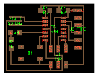
Design
The following editions were committed in the file. this code is added under #define board and before #select ouput. The PCB had trouble with placingthe 6mm push button, hence we had to resize the board make it wide and reposition IC. Code:
# define board
#
w = .016
width = 1.2
height = .93
mask = .004
x = 1
y = 1
z = -.005
d = .06
....Uneditted code
.
.
# repositioned the IC. Every other element seems to #positioned relative to the ic.
pcb = wire(pcb,w, IC1.pad[13],
point(IC1.pad[13].x+.105,J2.pad[4].y,z),
J2.pad[4])
.
.
.
#adding led
LED1=LED_1206('Led') #usually the format is like component_size('name')
pcb= LED1.add(pcb,XTAL1.x,IC1.pad[5].y,z,180) #showing the led
R2=R_1206('R2\n1k') #adding resistor and naming it "R2 1k"
pcb= R2.add(pcb,LED1.pad[2].x,LED1.y-0.15,z,-90)
B1=button_6mm('B1') #adding push button
pcb=B1.add(pcb,LED1.x+0.2,J1.y+0.05,z)
pcb = wire(pcb,w, #adding traces
IC1.pad[5],
LED1.pad[1])
pcb = wire(pcb,w,
LED1.pad[2],
R2.pad[1])
pcb = wire(pcb,w,
J1.pad[6],
R2.pad[2]
)
pcb = wire(pcb,w,
IC1.pad[6],
B1.pad[4]
)
pcb = wire(pcb,w,
J1.pad[6],
B1.pad[3]
)
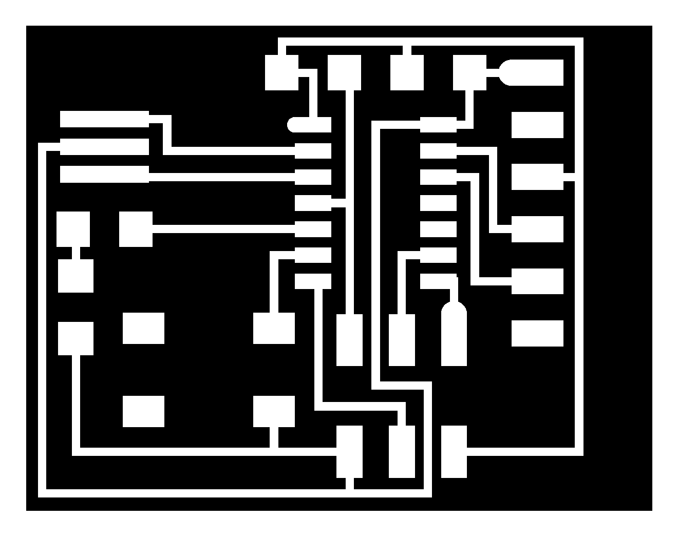
Exporting as .png
(make sure you name the file with the extension or else the export wont work and throw an exception)
# define board
#
w = .016
width = 1
height = .93
mask = .004
x = 1
y = 1
z = -.005
d = .06
It is not recommend below for trace width(w) to be lesser than 0.012. Assign intelligent values for these parameter and let it remain default unless theres a problem.
Design
The following editions were committed in the file. this code is added under #define board and before #select ouput. The PCB had trouble with placingthe 6mm push button, hence we had to resize the board make it wide and reposition IC. Code:
# define board
#
w = .016
width = 1.2
height = .93
mask = .004
x = 1
y = 1
z = -.005
d = .06
....Uneditted code
.
.
# repositioned the IC. Every other element seems to #positioned relative to the ic.
pcb = wire(pcb,w, IC1.pad[13],
point(IC1.pad[13].x+.105,J2.pad[4].y,z),
J2.pad[4])
.
.
.
#adding led
LED1=LED_1206('Led') #usually the format is like component_size('name')
pcb= LED1.add(pcb,XTAL1.x,IC1.pad[5].y,z,180) #showing the led
R2=R_1206('R2\n1k') #adding resistor and naming it "R2 1k"
pcb= R2.add(pcb,LED1.pad[2].x,LED1.y-0.15,z,-90)
B1=button_6mm('B1') #adding push button
pcb=B1.add(pcb,LED1.x+0.2,J1.y+0.05,z)
pcb = wire(pcb,w, #adding traces
IC1.pad[5],
LED1.pad[1])
pcb = wire(pcb,w,
LED1.pad[2],
R2.pad[1])
pcb = wire(pcb,w,
J1.pad[6],
R2.pad[2]
)
pcb = wire(pcb,w,
IC1.pad[6],
B1.pad[4]
)
pcb = wire(pcb,w,
J1.pad[6],
B1.pad[3]
)
Exporting as .png
(make sure you name the file with the extension or else the export wont work and throw an exception)
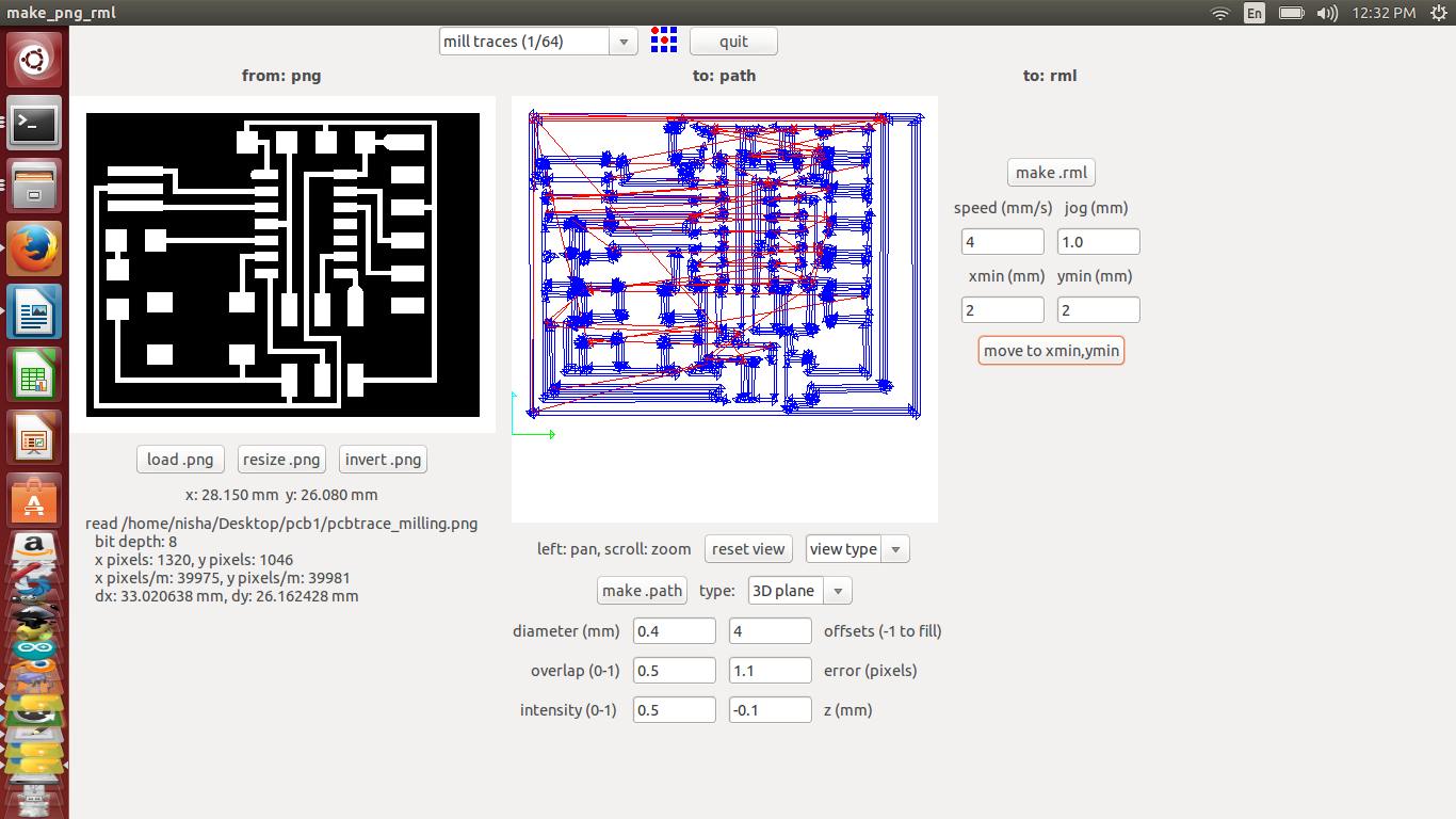
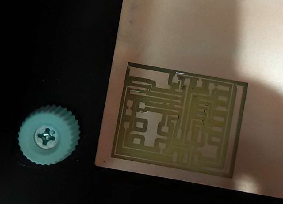
Machining
Machining parameter
Milling output
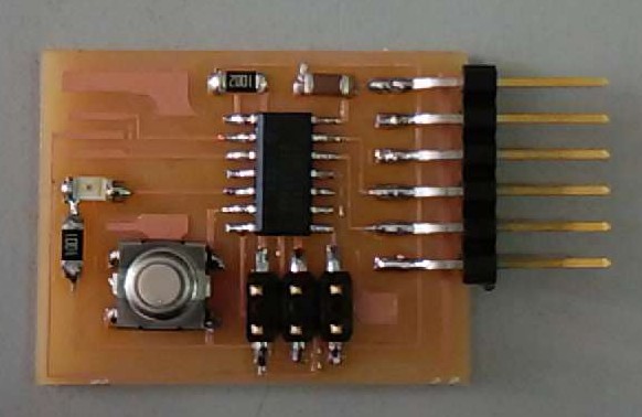
Final Output after stuffing with components.