Output Devices
OverviewLast updated: 03/07/2016
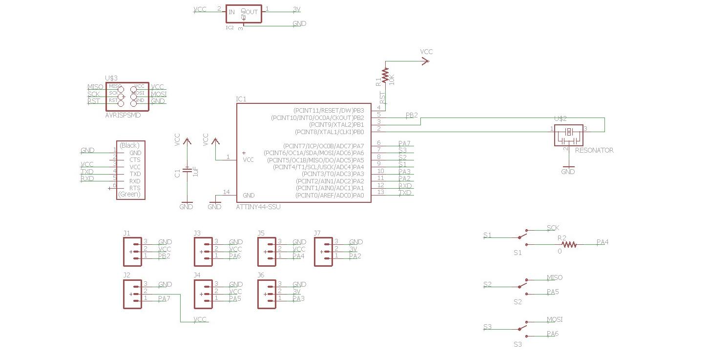
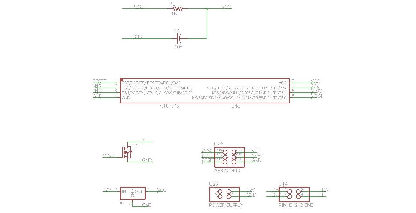
Objective Add an output device to a microcontroller board you've designed and programme it to do something. Learning outcomes 1.Demonstrate workflows used in circuit board design and fabrication; 2.Implement and interpret programming protocols; Have I... Explained the programming process/es I used and how the microcontroller datasheet helped me? Outlined problems and how I fixed them? Included original design files and code? Summary During this week I mainly did two things. On the one hand I designed a board where I could attach output devices. To test it I attached it to a servo motor. It is called "Tha Board". On the other hand I built and programmed the speaker board.Tha Board Manufacturing Tha Board evolved from the breakout sensor board that I designed in week 11 [1]. It mounts an Attiny44 and it can be attached to 2 x 3.3V peripherals and 5 x 5V peripherals. It follows the BOM.
| Amount | Component | Schematic | Code |
|---|---|---|---|
| 1 | ATTiny44 | IC1 | RS 696-251 |
| 1 | RES 20 MHz | XTAL1 | DigiKey XC1109CT |
| 1 | 10K Ohm | R1 | RS 223-2394 |
| 1 | 1 microF | C1 | RS 766-1062 |
| 1 | 0 Ohm | R5 | RS 679-1768 |
| 1 | 3.3V | V Divider | |
| 3 | Switch |
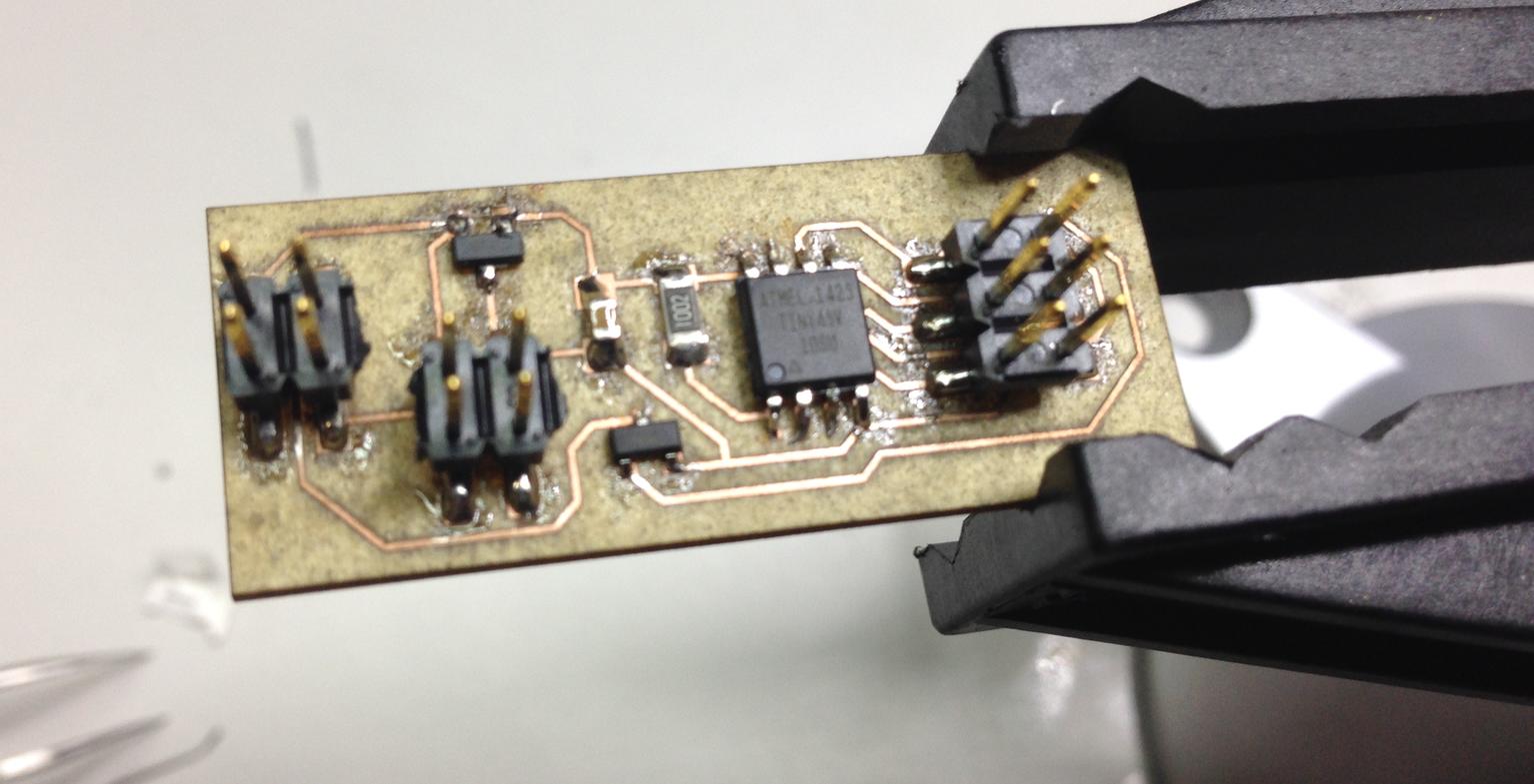
 Since I wanted to learn how to manifacture a dual layer board, I decided to do it, even though it was not really necessary. Working with two layers in Eagle is quite intuitive, even though you get a bit cross-eyed after a while. It was a fun exercise.
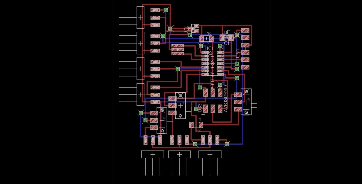 In order to manufacture it I used the laser cutter. I carefully positioned the double-layer PCB so that the two images would properly match. It did turn out quite well actually. The only problem that I encountered were the holes that did not totally get open. Next time I should probably do two passes. I used the legs of regular resistors to connect the two layers.
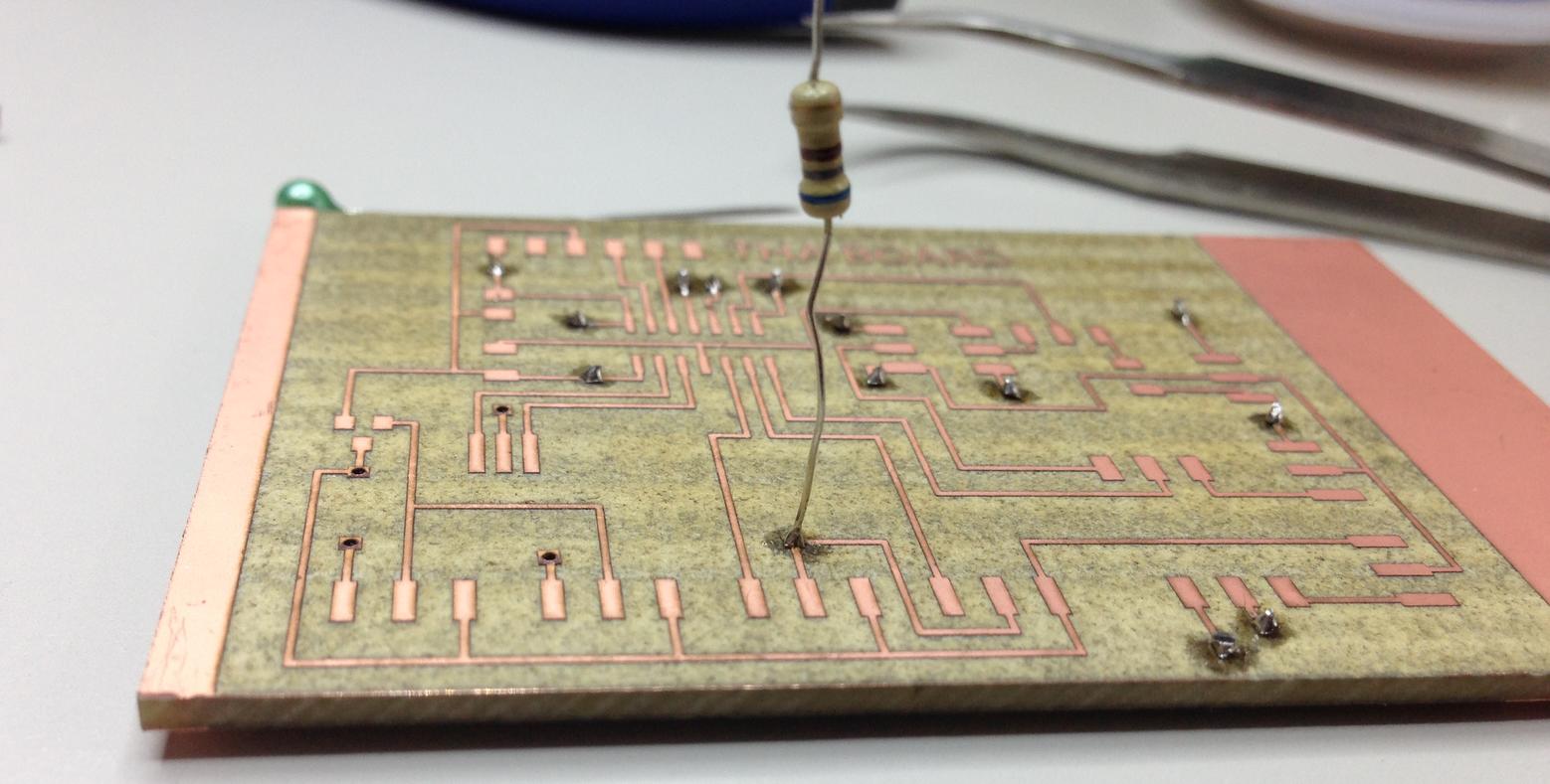 The final result is shown below, where the three switches can either enable the use of the ISP connector or the use of 3 pinout sets.
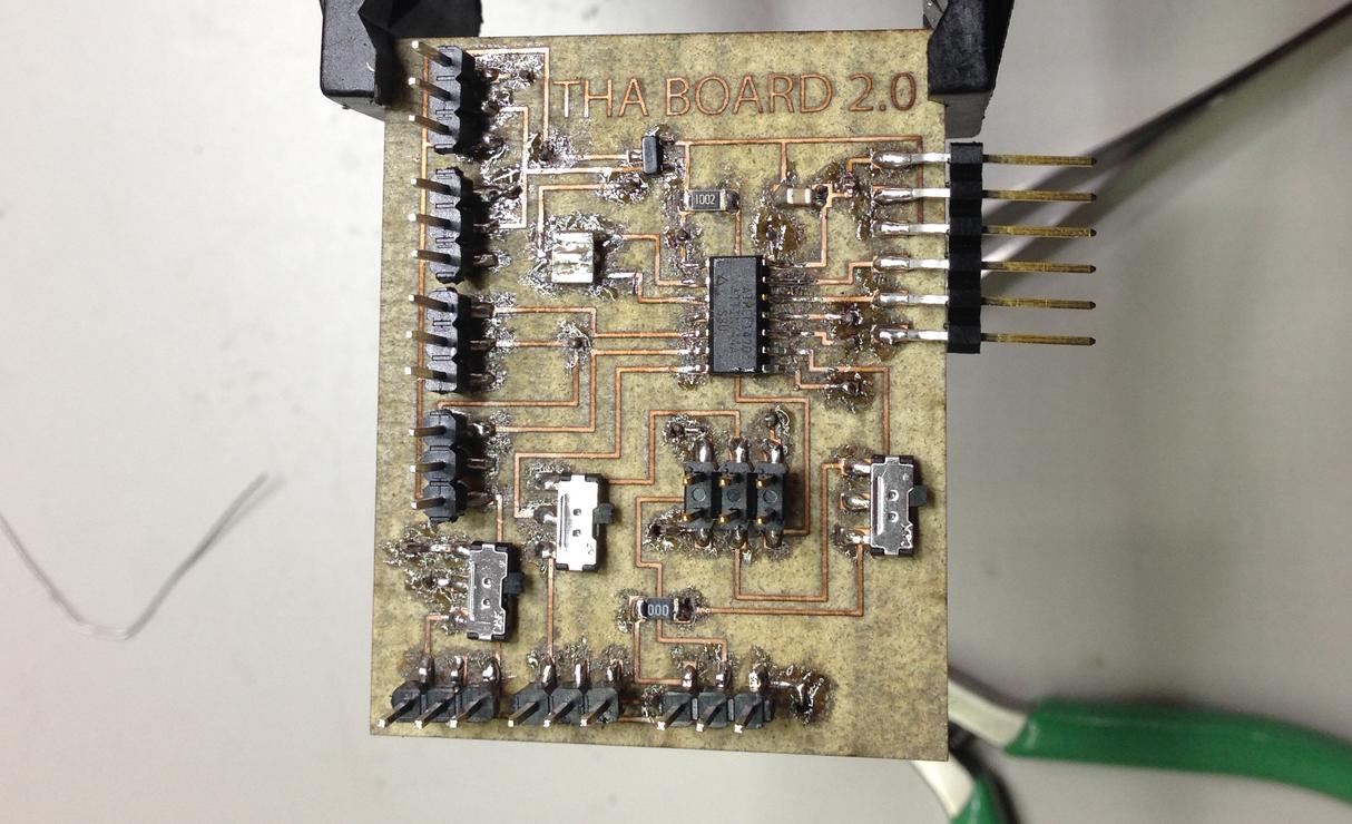
Tha Board Programming I attached this servo motor to the board and I programmed it to perform a simple back-forth 180 degrees rotation. The layout of Tha Board really worked out, as I just had to plug the motor in, as shown in the picture below.
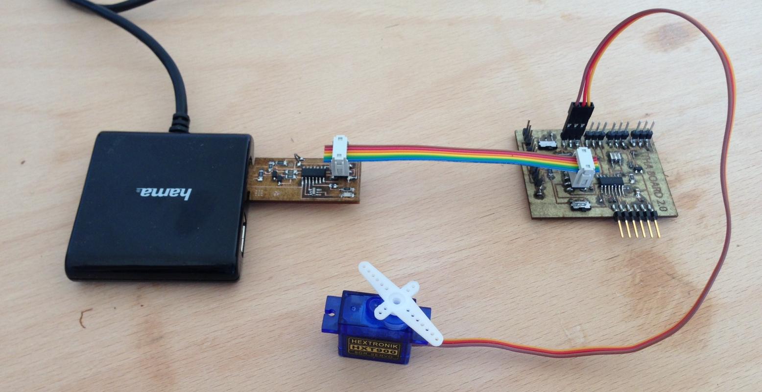 To test the electronics I simply used one of the example sketches of the Arduino Servo library, that is already included in with the software download.
/* Sweep
 by BARRAGAN
 This example code is in the public domain.

 modified 8 Nov 2013
 by Scott Fitzgerald
 http://www.arduino.cc/en/Tutorial/Sweep
*/

#include < Servo.h>

Servo myservo;  // create servo object to control a servo
// twelve servo objects can be created on most boards

int pos = 0;    // variable to store the servo position

void setup() {
  myservo.attach(PA7);  // attaches the servo on pin PA7
}

void loop() {
  for (pos = 0; pos <= 180; pos += 1) { // goes from 0 degrees to 180 degrees
    // in steps of 1 degree
    myservo.write(pos);              // tell servo to go to position in variable 'pos'
    delay(15);                       // waits 15ms for the servo to reach the position
  }
  for (pos = 180; pos >= 0; pos -= 1) { // goes from 180 degrees to 0 degrees
    myservo.write(pos);              // tell servo to go to position in variable 'pos'
    delay(15);                       // waits 15ms for the servo to reach the position
  }
}
Speaker As a second exercise I took this board and I made it with no changes. The schematic is below;
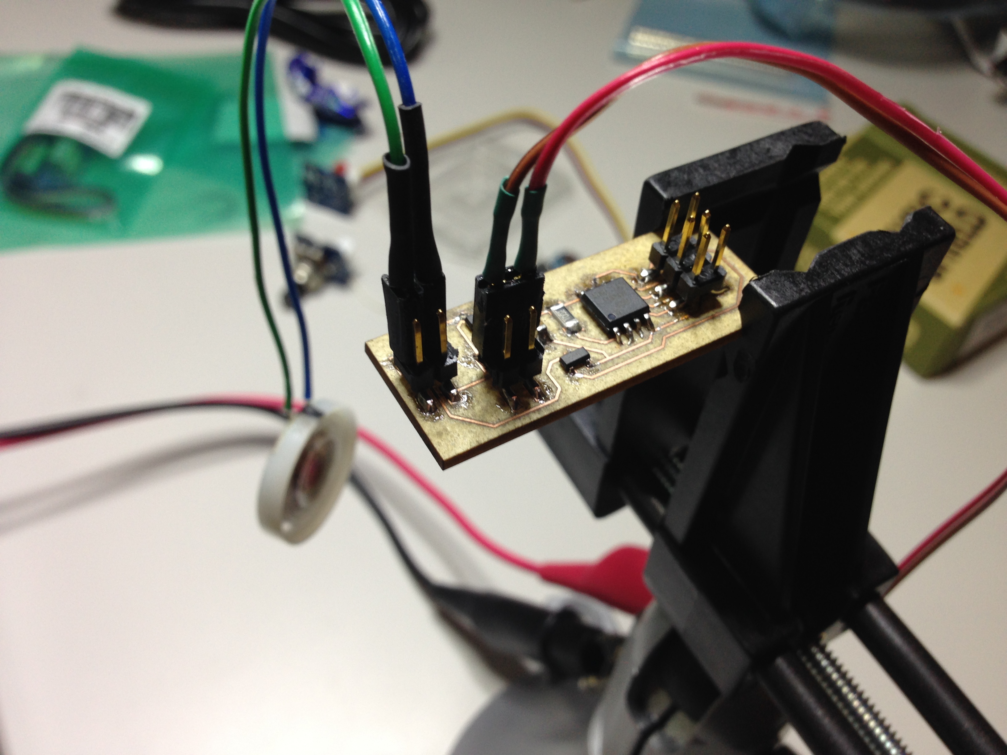
 The board came out pretty okay. This time I decided to have 45 degrees cuts in the traces, for a change. I did not really like it, so I will get back to my usual style in the future.
 Attaching the speaker was quite easy. I used an external power generator with 12V delivering 200mA.
 For programming I simply used Neil's sketch. The result is shown with the video below.
Conclusions The balance for this week is overall positive: I learned how to make a double layer board and I have one board that I can reuse again in the future, with all the limits of the ATTiny44 flash memory, of course. Emotionally speaking I got a bit lost and frustrated during this week, that is also why I only completed it at the end of the semester. I think the cause of this is that I had not really clear in my head what I wanted to do for my final project and I pretty much did two output devices without a purpose.