#Exercise_6
2/03/2016
Assignment
Electronics designRedraw the echo hello-world board and add at least a button and LED with current-limiting resistor or design your own.
- Select and use software for circuit board design
- Demonstrate workflows used in circuit board design
- Make the hello-board
Design the hello-board
Tools
- Eagle electronic cad software
- Roland MDX-40A
- SMD soldering stuff
For the assignment I have decided to use Eagle electronic cad software and the plug-in pcbgcode to make the board. I have redraw the original board and added a button and two smd led, one green and the oder one red.
Draw the board on Eagle
2nd step: in order to proceed I have saizing the components that I will use to make board.
Saizing the smd led resistors:
I have applied the first Ohm law's; from datasheet both the SMD led PLCC-2 Vf = 1.9V and if = 20mA, the Vs = 5V. I decided to use less current of max Vf, near 12mA.
I will use the nearest standar resistor of the serie taht we have in the lab, so a 390Ohm 5%.
Saizing the push button:
in order to obtain a good performance I decide to use a little capacitor of 0.1uF to obtain an antibounce solution; and I used a 10Kohm resistor for a pull-down solution instead of the integreted one of the attiny pin.
Power input:On the power line we have a 1uF capacitor in order to stabilize the power input.

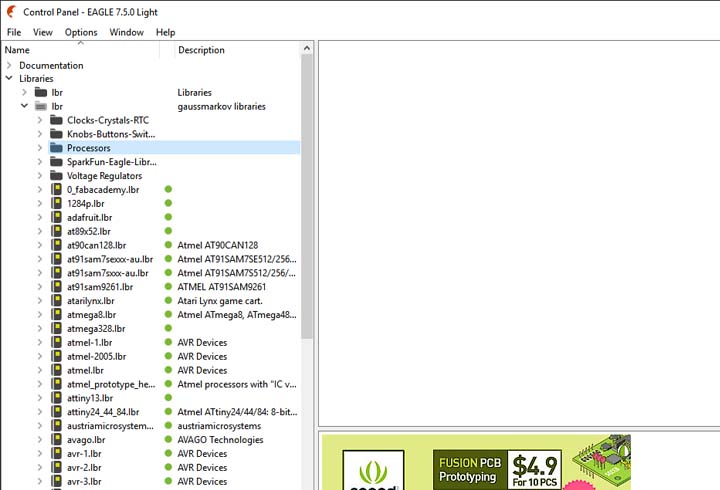
3rd step: adding some libraries (fabacademy lirary, sparkfun and adafruit libraries) to Eagle in order to have available all the needed components, I have followed this tutorial.
Useful Eagle tutorials.
4th step: create a new project and schematics, after add all the components of the boards to the canvas.
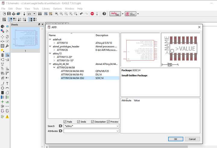
Tip: to add a component using the add command, could be usefull to use the * before and after the search word, in order to obtain a good result (thanks to Gianfranco for the tip).
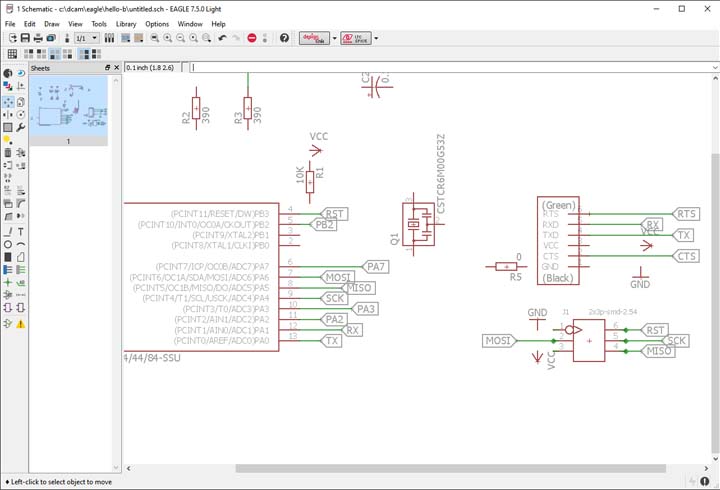
5th step: add the lable with Xref on for each pin that we must connect, in order to obtain an ordered shematics.
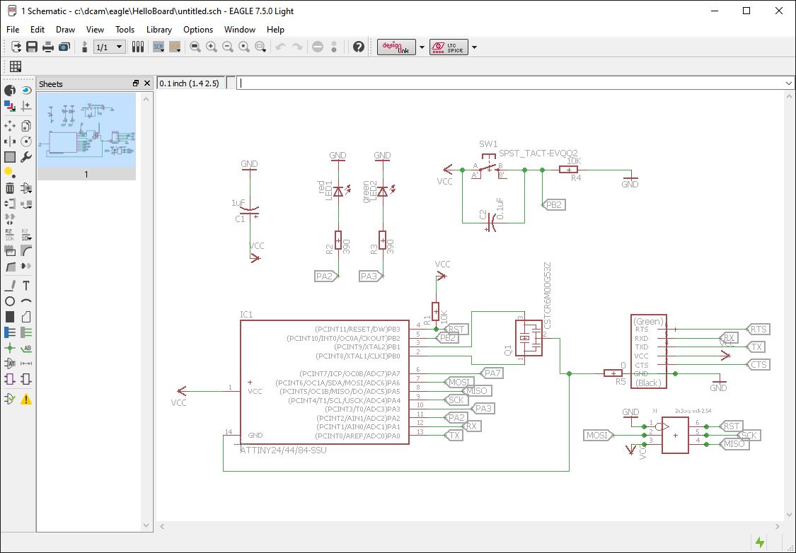
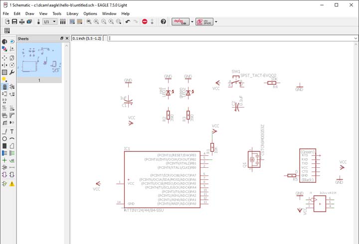
6th step connect all the components at the right place and obtain the schematic.
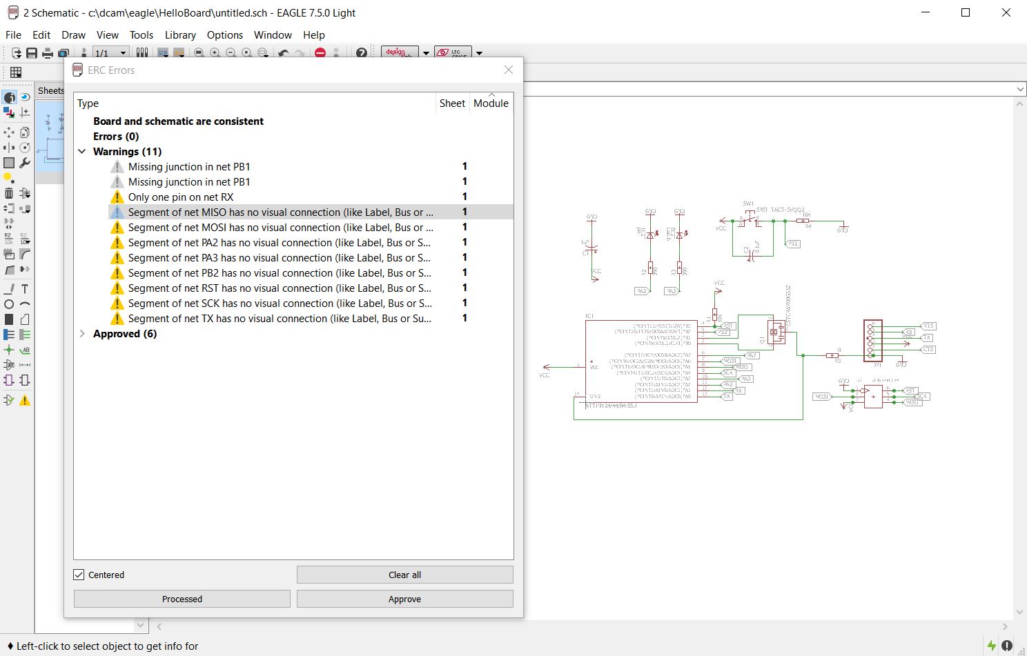
7th step: run the ERC function and check for errors, if needed correct the errors.
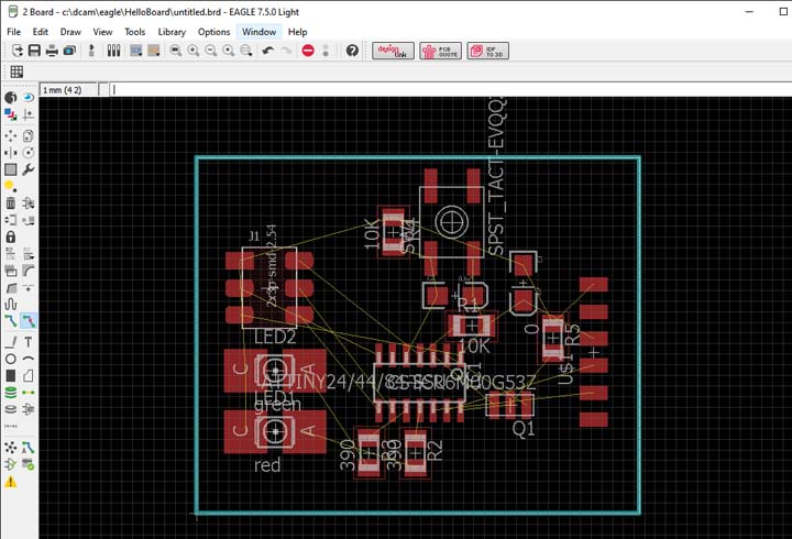
8th step: generate the board, positioning all the components and draw the milling ouyline.
I took a lot of time to make the final rooting, so I learned that the position of the components are very important to obtain good results and an easy work at the routing time.
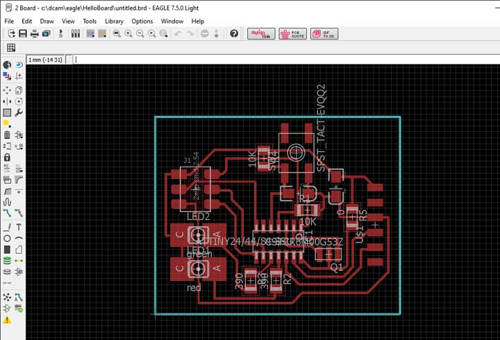
9th step: I started to use the autorute function, but I not reached sadisfactorily results. So I ruted all the PCB manually, and this took a lot of time.
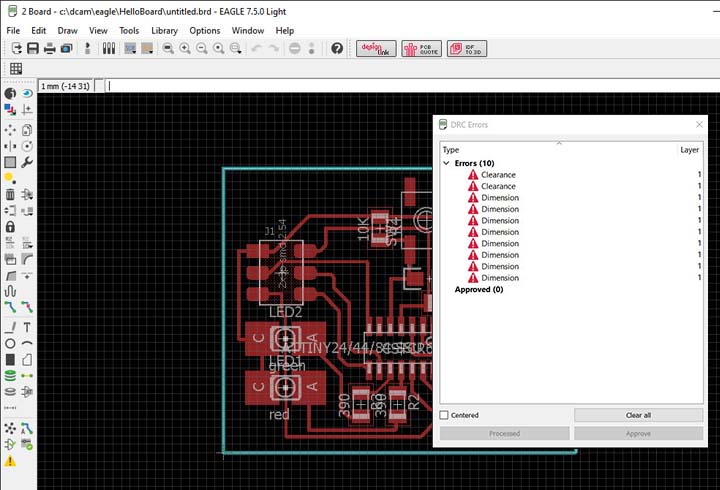
10th step run the ERC function and check for errors, if needed correct the errors.
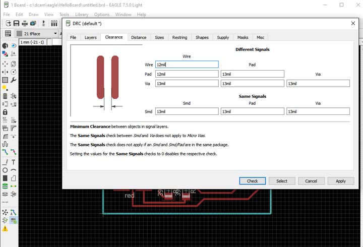
11th step: run the DRC function and check the distance between each traces, pads and ect to make sure that we have at least the thickness of the head of our v shape bit.
Mill and solder the Hello board

1st step: in order to make the board I used the pcbgcode Eagle plug-in, following the same process described and experimentate in the module number 4, Electronics production please see this link.
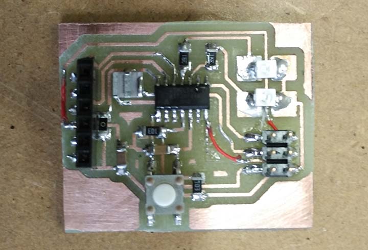
2nd step: results after milling and soldering.
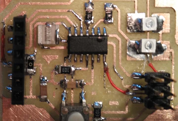
Errors: after the PCB milling as usual I sended the board with send paper, but during the process I push a little bit too much and I washed-up a couple of traces; so I repared these soldering a jumper wire. The washed-up traces was very thin 11mil.
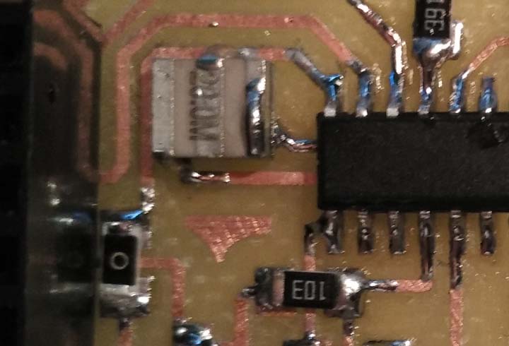
Errors: when I designed the schematic I have used a wrong package for the resonator, a little bit too small! I realized the error only at the end, because was the last component that I soldered.
Soldering the resonator was very hard, a surgical operation but I have no shorts, and work.
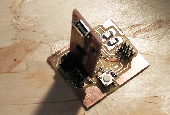
the FTDI connected to the board.
Testing the board: I connected the board to the laptop through the FTDI and I have got no smoke, in the next days I will program it.
1rst step: I started to spent some time to make the BOM and consult the components datasheets.
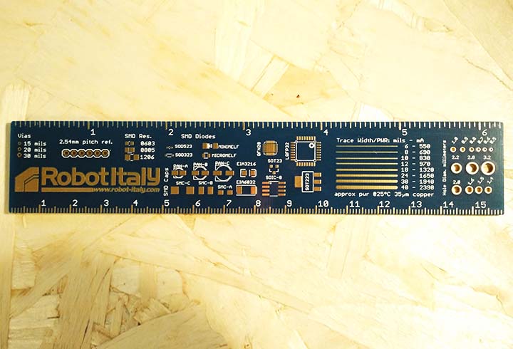
Saizing the traces width:
The most stressed trace must support 80mA of current, so to sizing the traces I used the robot Italy ruler. With a 35um of copper thickness at 25ºC and ^10ºC/A I could use the smollest 6mil trace. But this dimension is too small to mill so I decided to use 16mil traces and when nedeed 12 mil traces.