Roosvelth Cántaro's Academy

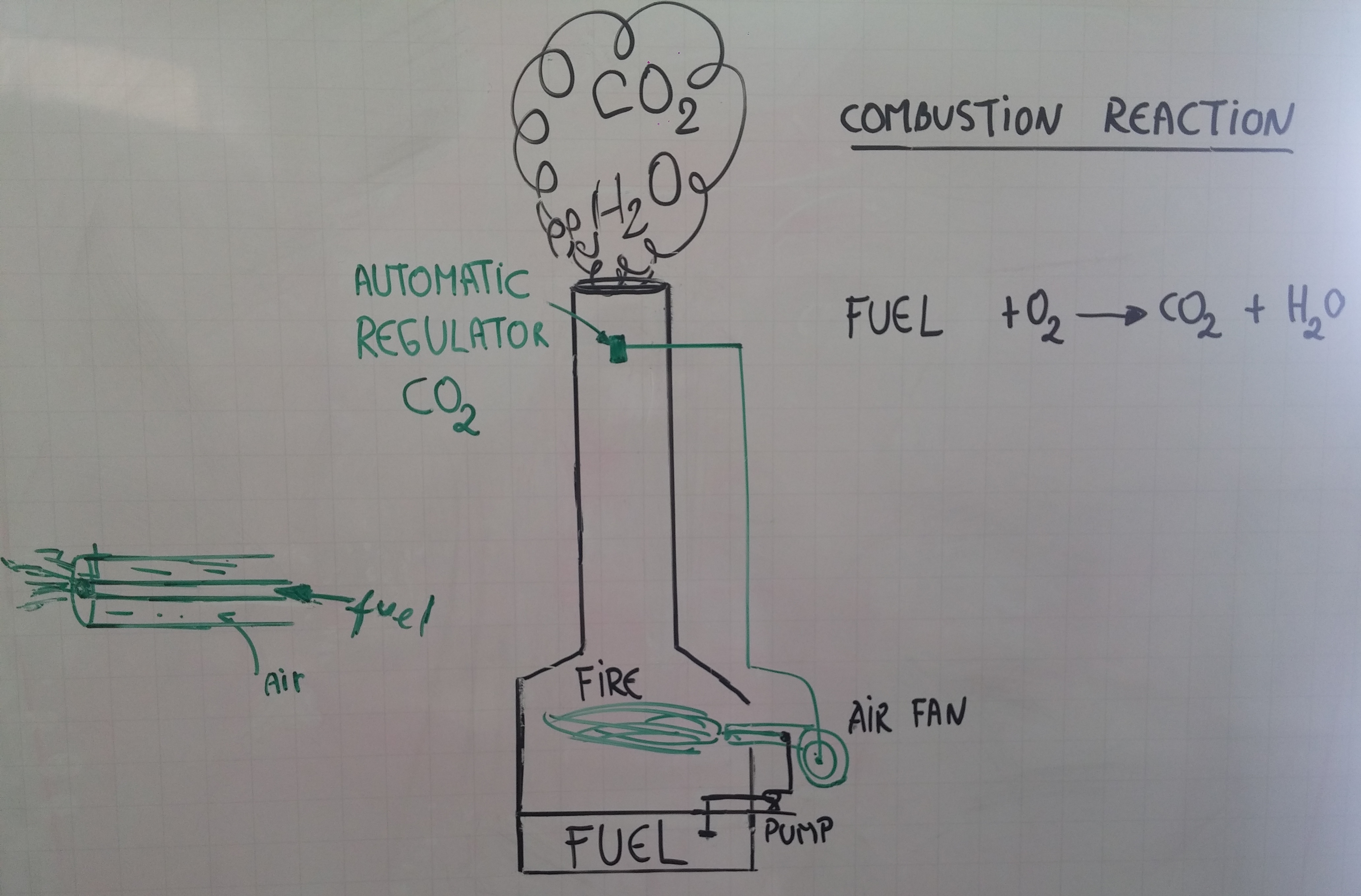
It was not easy to choose my final project as a Chemical Engineer I'm new to Digital Fabrication. My final project will be an Automatic mixture regulator for an air-fuel mixture. The idea would be the speed regulation of an air blower for presence of carbon dioxide in smokestacks.
This is an investigation on green chemistry. The idea is to develop a speed regulator of an air blower using a sensor which recognizes the presence of carbon dioxide from smokestacks. The research proposed, has relation whith the combustion reaction which can be complete and incomplete. The variations in fan speed depends on the content of carbon dioxide.
- Principles and practices, project management
- Computer - aided design
- Computer - controlled cutting
- Computer - controlled machining
- Composites
- Electronics (Production, Design, Programming, Input and Output Devices)
- Interface and application programming
- Project development
- Project presentation
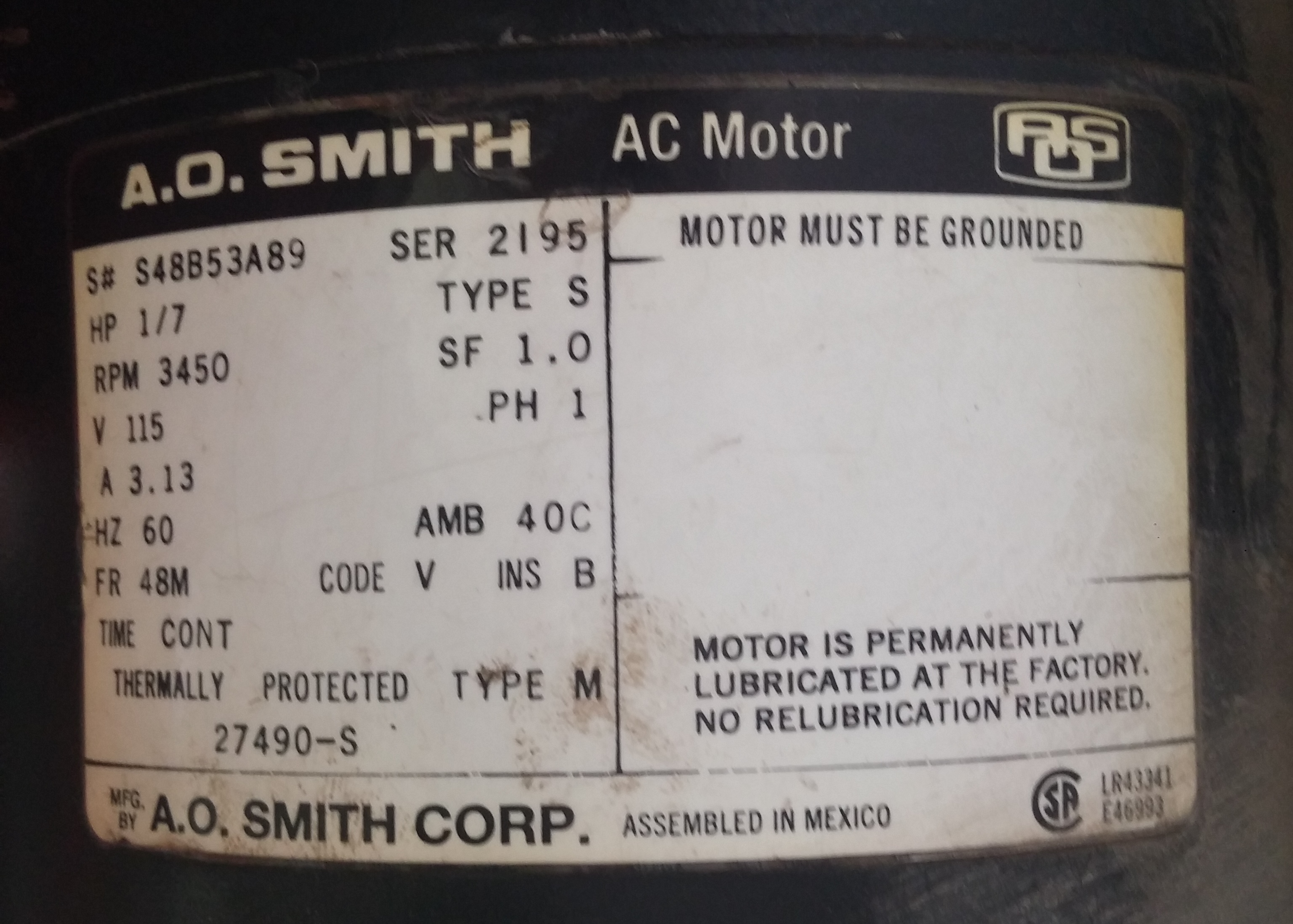
Nowadays more efficient methods are used for operational control of equipement and units, for example: The furnace fire testing laboratory has a power and automatic temperature controller, but needs a speed controller for the airflow.
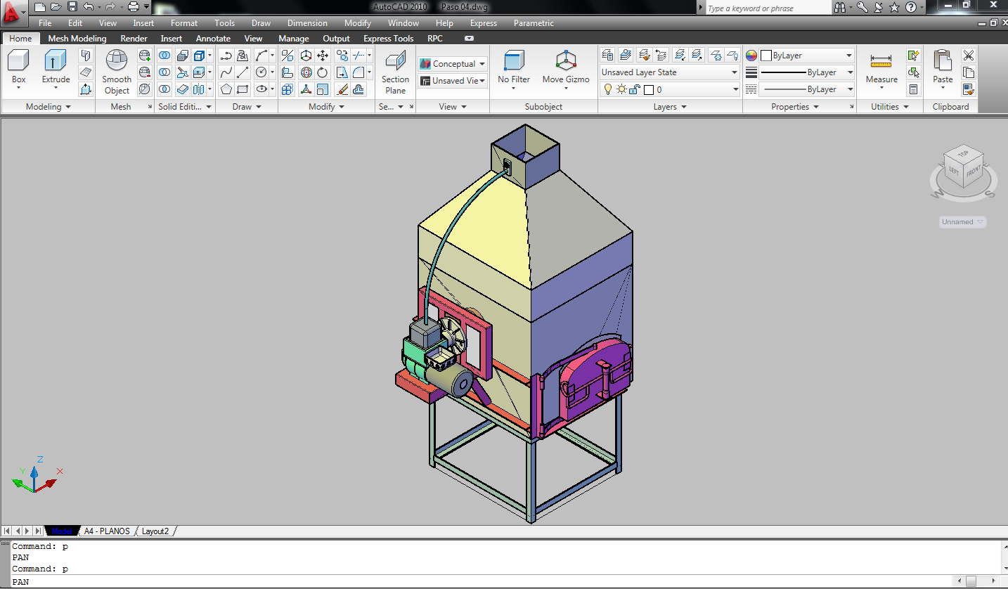
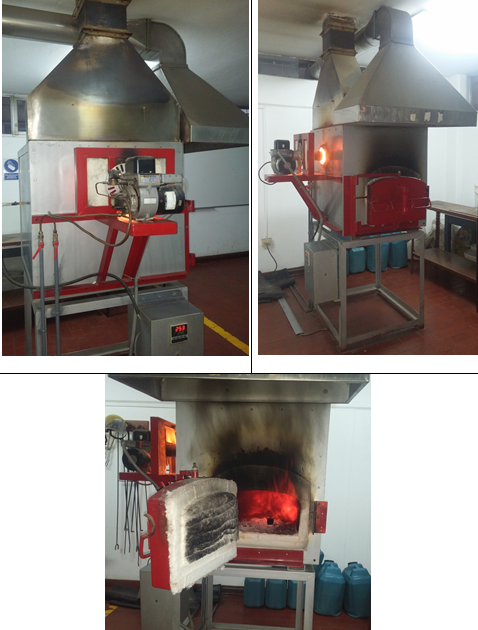
The project is to develope a controller to automatically adjust the air flow. The maximum operating temperature of the furnace is 1200°C and uses diesel fuel. Heating the minerals at high temperatures to release the volatiles components.
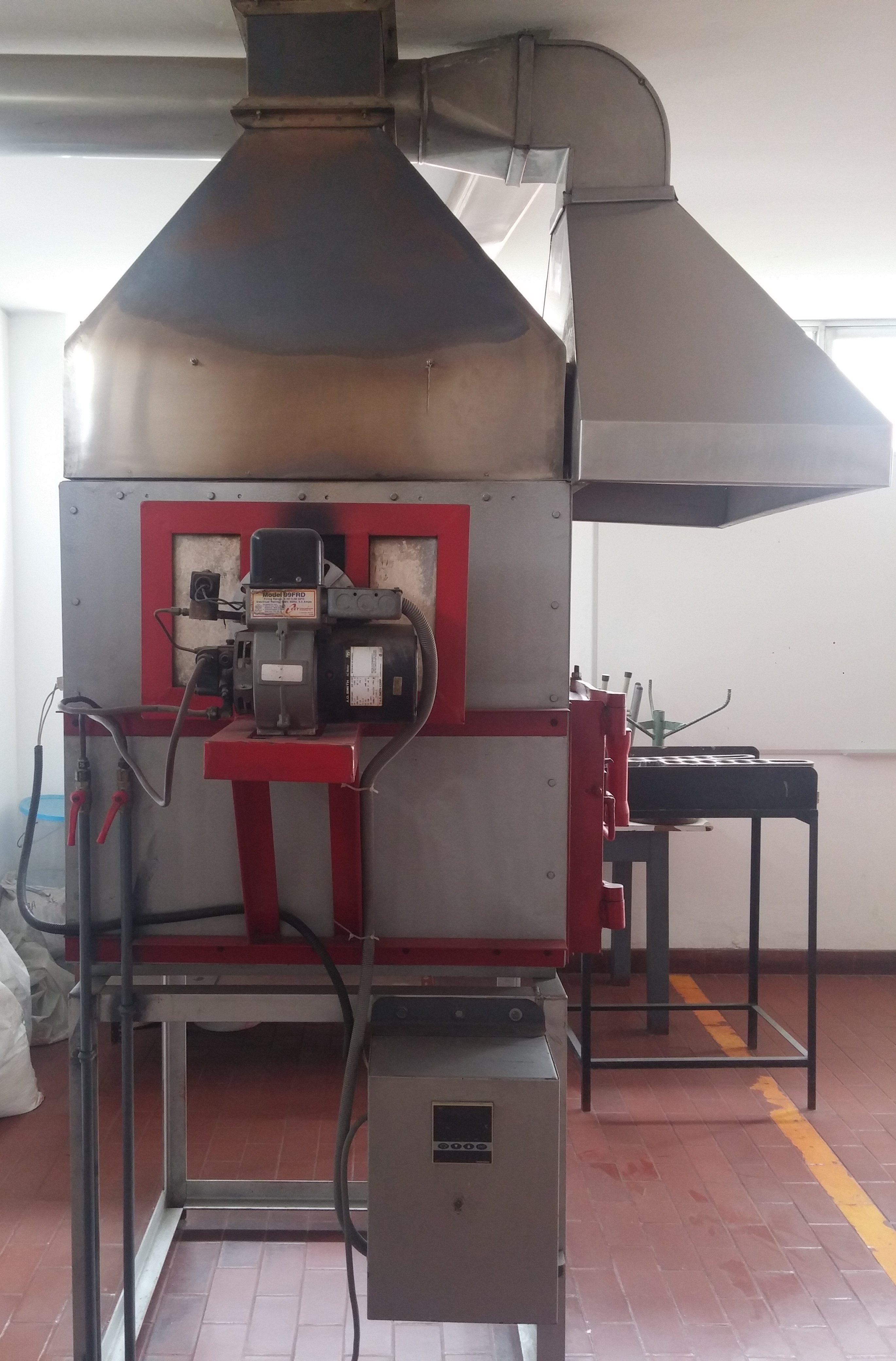
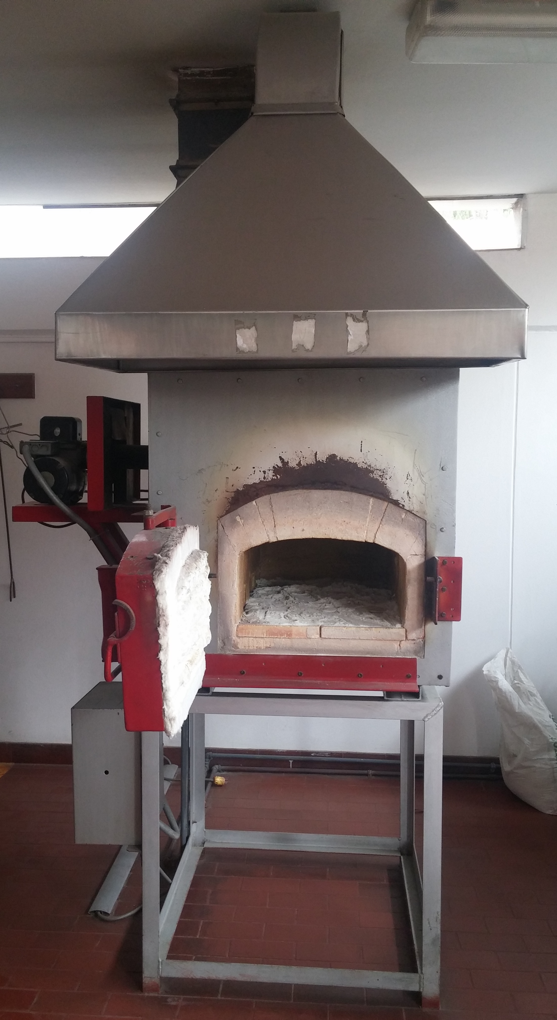
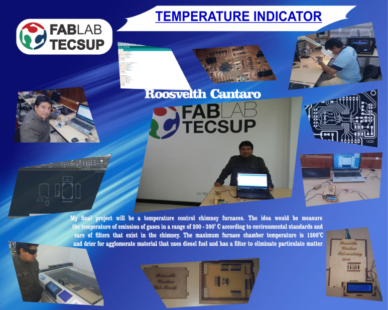
My final project will be temperature indicator chimney furnaces. The idea would be measure the temperature of emission of gases in a range of 100 - 300° C according to environmental standards and care of filters that exist in the chimney. The maximum furnace chamber temperature is 1200°C and drier for agglomerate material that uses diesel fuel and has a filter to eliminate particulate matter
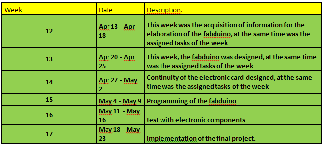
Links to any weeks that you worked on your final project:
At week 16 was performed PT100 temperature sensor control , this sensor is used by industries for recording high temperatures , the objective of the RGB LED is to indicate that the temperature ranges is almost cold blue PT100 temperature sensor , ( temperatures below 30 ° C ), green ; medium temperatures ( over 30 ° C and less than 60 ° C ) , and finally red are high temperatures ( 60 ° C ) . Where is a breakthrough for the final project?
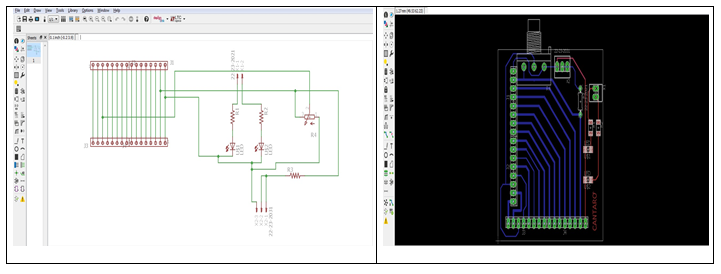
In the assignments N°6, I downloaded the software EAGLE and for my project final I worked witch this software in schematic and board design.
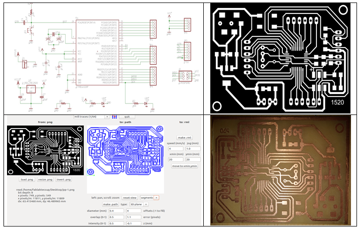
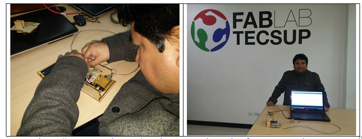
For this Project, I designed a board FabDuino available in the FABLAB TECSUP for can to use programming IDE-ARDUINO, to view temperatures in the LCD, using ARDUINO library.
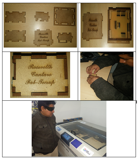
Then I'll show the following figures:
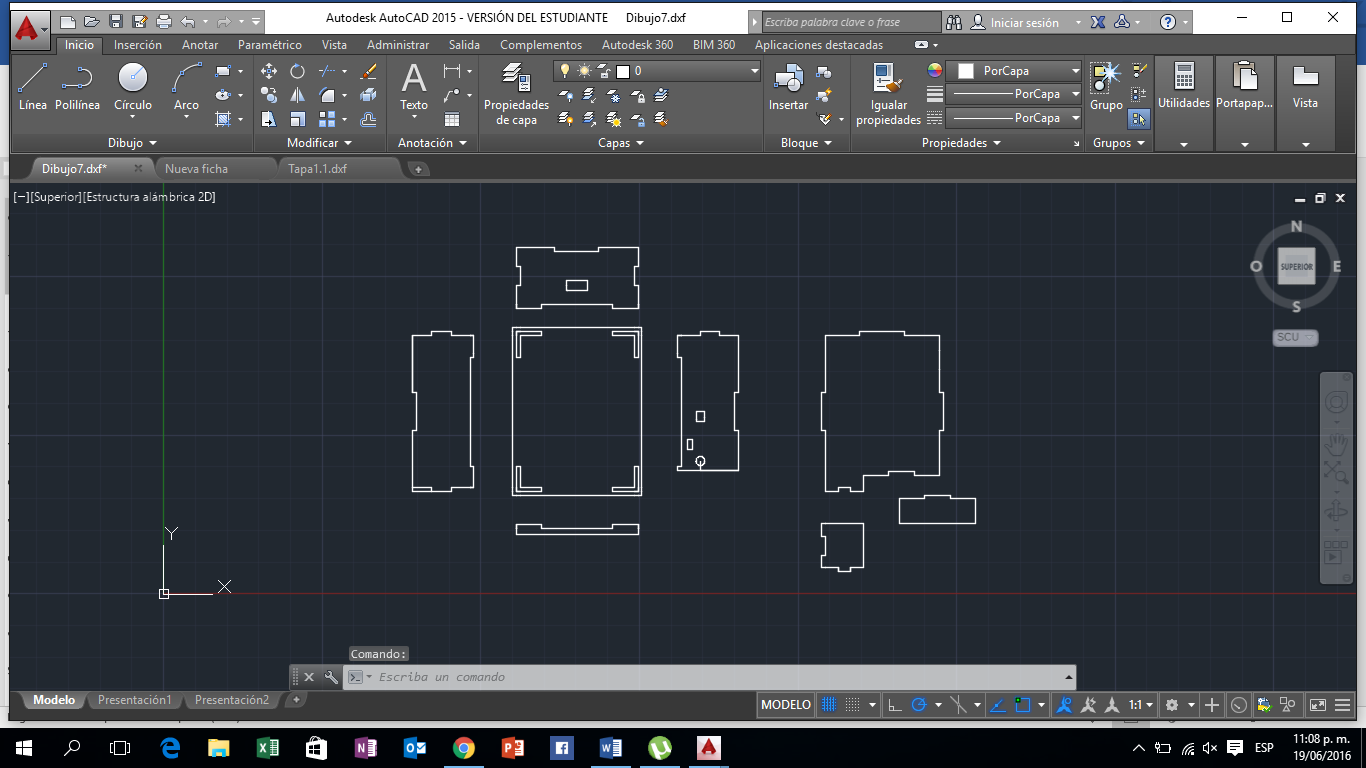
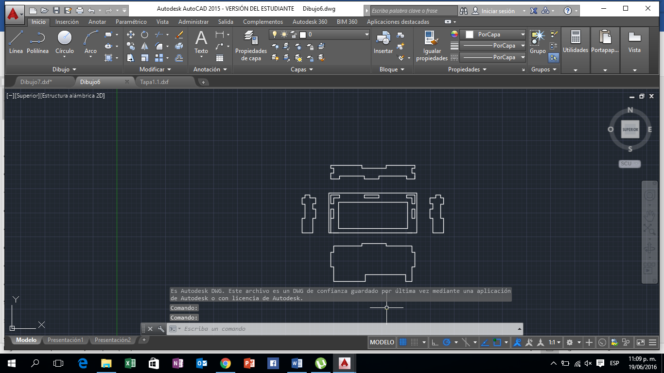
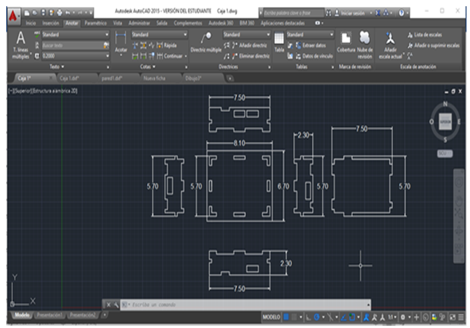
- Design FABDUINO
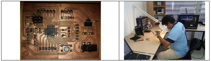
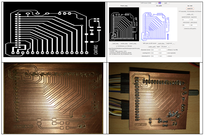
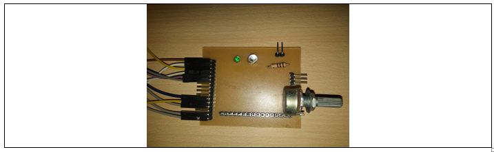
- Board FABDUINO
- Milling machine FABDUINO
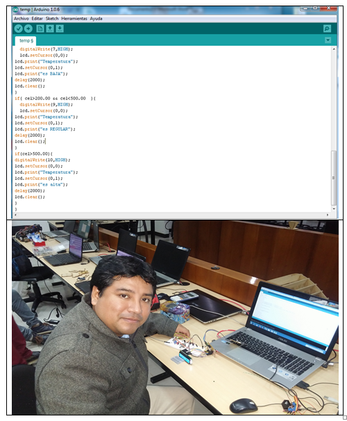
For the final project I used the software IDE ARDUINO for the programming the FABDUINO, because I had the motion of the assignment N°8. I began working on the programming using the library “LiquidCrystal.h” in order to use the LCD 2x16. The programming consists of acquiring PT100 sensor data and expresses them in temperatures to view them on the LCD.
The objective of this programming is to visualize the temperature of the chimney furnace and to indicate us if we are to a low temperature (low temperatures to 200°C), comes up (temperatures between 200°C to 500°C) or high temperatures (higher to 500°C).
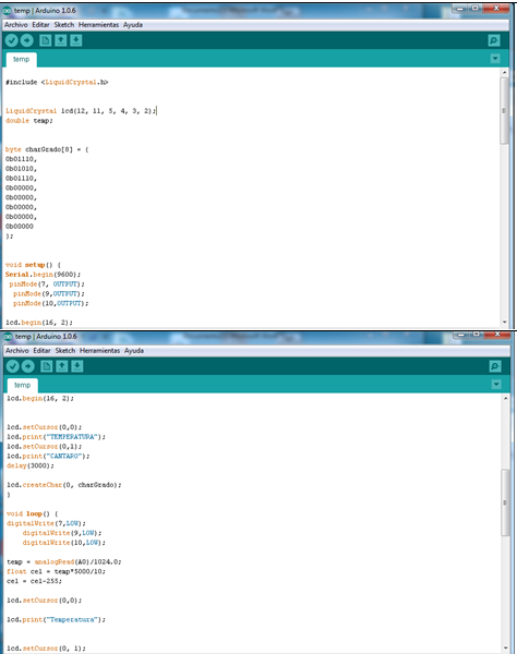
This allows connecting the plate FABDUINO with the LCD in order to view the collected temperature data acquired by PT-100.
I used AutoCAD software to design circuit protection, due to work with high temperatures; this can to cause a problem in the connections. The necessary temperature when welding the plates is 130 °C, therefore, the protection of each plate was performed.
Protection Fabduino.
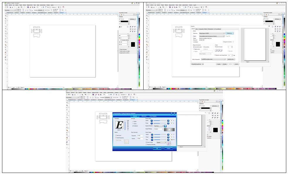
For printing, I used the program Corel Draw. The printing steps they are:
- Design location in the printing plate.
- Then we enter the settings in the preferences option.
- Then we introduce the plate size used is 900 x 600, then the vector option, which is to print, and raster option is selected, it is for engraving name.
I wanted to relate the Fab academy 2016 with industrial needs; I think that if I did it. Create a temperature indicator for be measure the temperature of emission of gases in the chimney furnaces.
By making my final project, I learned develop an idea, uses of micro-electronic components: Electronic design, programming (I used the software IDE ARDUINO), Computer-controlled cutting and I used the fab-lab Tecsup machine, and more. With this instrument, I could measure temperature emission of combustion gases and I check with other the measurement instruments calibrated and little room for error ( 1°C).
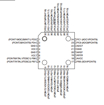
Pin configurations:
1.1.1 VCC
Digital supply voltage.
1.1.2 GND
Ground.
1.1.3 Port B (PB7:0) XTAL1/XTAL2/TOSC1/TOSC2
Port B is an 8-bit bi-directional I/O port with internal pull-up resistors (selected for each bit). The Port B output buffers have symmetrical drive characteristics with both high sink and source capability. As inputs, Port B pins that are externally pulled low will source current if the pull-up resistors are activated. The Port B pins are tri-stated when a reset condition becomes active, even if the clock is not running. Depending on the clock selection fuse settings, PB6 can be used as input to the inverting Oscillator amplifier and input to the internal clock operating circuit. Depending on the clock selection fuse settings, PB7 can be used as output from the inverting Oscillator amplifier. If the Internal Calibrated RC Oscillator is used as chip clock source, PB7..6 is used as TOSC2..1 input for the Asynchronous Timer/Counter2 if the AS2 bit in ASSR is set.
1.1.4 Port C (PC5:0)
Port C is a 7-bit bi-directional I/O port with internal pull-up resistors (selected for each bit). The PC5..0 output buffers have symmetrical drive characteristics with both high sink and source capability. As inputs, Port C pins that are externally pulled low will source current if the pull-up resistors are activated. The Port C pins are tri-stated when a reset condition becomes active, even if the clock is not running.
1.1.5 PC6/RESET
If the RSTDISBL Fuse is programmed, PC6 is used as an I/O pin. Note that the electrical characteristics of PC6 differ from those of the other pins of Port C. If the RSTDISBL Fuse is programmed, PC6 is used as a Reset input. A low level on this pin for longer than the minimum pulse length will generate a Reset, even if the clock is not running.
1.1.6 Port D (PD7:0)
Port D is an 8-bit bi-directional I/O port with internal pull-up resistors (selected for each bit). The Port D output buffers have symmetrical drive characteristics with both high sink and source capability. As inputs, Port D pins that are externally pulled low will source current if the pull-up 4 2545US–AVR–11/2015 ATmega48/88/168 resistors are activated. The Port D pins are tri-stated when a reset condition becomes active, even if the clock is not running.
1.1.7 AVCC
AVCC is the supply voltage pin for the A/D Converter, PC3:0, and ADC7:6. It should be externally connected to VCC, even if the ADC is not used. If the ADC is used, it should be connected to VCC through a low-pass filter. Note that PC6..4 use digital supply voltage, VCC.
1.1.8 AREF
AREF is the analog reference pin for the A/D Converter.
1.1.9 ADC7:6 (TQFP and QFN/MLF package only)
In the TQFP and QFN/MLF package, ADC7:6 serve as analog inputs to the A/D converter. These pins are powered from the analog supply and serve as 10-bit ADC channels.
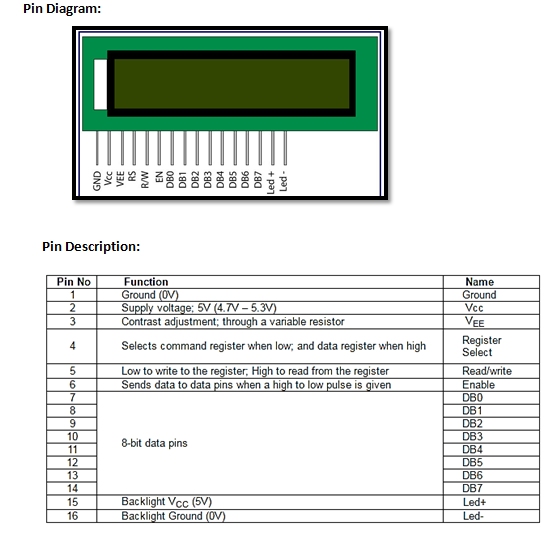
LCD 16X2:
LCD (Liquid Crystal Display) screen is an electronic display module and find a wide range of applications. A 16x2 LCD display is very basic module and is very commonly used in various devices and circuits. These modules are preferred over seven segments and other multi segment LEDs. The reasons being: LCDs are economical; easily programmable; have no limitation of displaying special and even custom characters (unlike in seven segments), animations and so on.
A 16x2 LCD means it can display 16 characters per line and there are 2 such lines. In this LCD each character is displayed in 5x7 pixel matrix. This LCD has two registers, namely, Command and Data.
The command register stores the command instructions given to the LCD. A command is an instruction given to LCD to do a predefined task like initializing it, clearing its screen, setting the cursor position, controlling display etc. The data register stores the data to be displayed on the LCD. The data is the ASCII value of the character to be displayed on the LCD. Click to learn more about internal structure of a LCD.
LCD