Exercise 14 - Composites
Assignment
Class assignment for this week:
- Design and make a mold (~ft^2)
- Produce a fiber composite from it
Mold Design
For my mold design, I decided to make use of a new software, Autodesk Fusion 360, rather than Inventor or SketchUp, which I have used earlier. My reason for doing this is because Fusion 360 comes highly recommended and it also comes with an integrated CAM component. This would make producing the gcode files from my design much easier, as compared to using Mastercam, which is a very tightly controlled software in our environment.
The Autodesk Fusion 360 GUI is very similar to Autodesk Inventor, so it should be a shorter learning curve for anyone who is familiar with Inventor. The software is available on both the Windows and OSX platform, though not on Linux, unfortunately. The main difference is that Fusion 360 saves its files on the cloud and you need to be signed in to be able to use the software. There is an offline mode, which I have not explored.
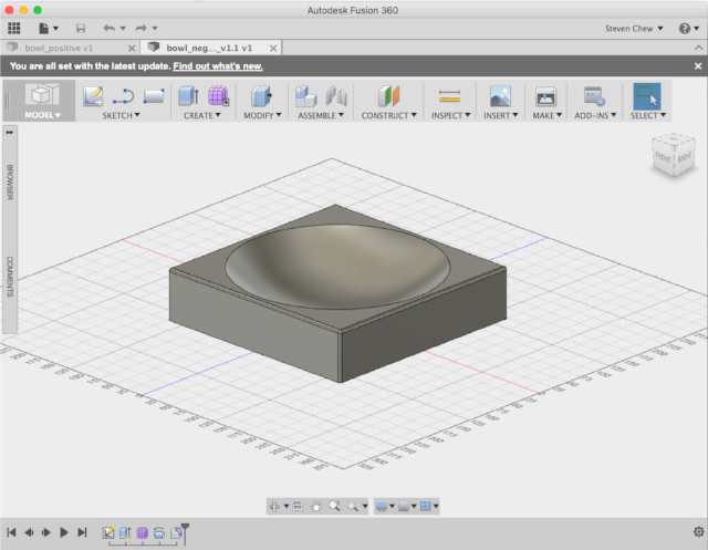
The next question for me was what to design for my composites assignment. I toyed around with a few ideas, e.g. an Ironman face mask, prosthetics, making a newspaper box for my house. I finally decided to try out 2 different ways of making a smmoth, curved surface (aka bowl). The reason I'm doing this is because I hope to be able to make the Star Wars BB8 droid at some point in the future. We also recently commissioned our vacuum press machine and had our vendor training. I asked our trainer what was the best way of creating a semi-sphere and it seems that the best approach would be to form it as an inverted semi-sphere. Let's see how a manual method works for my composites assignment.
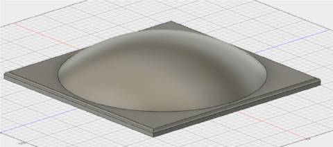
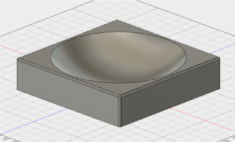
The 2 bowls that I designed are shown in the pictures below. The bowls are quite shallow because the blue foam that we have are 1" and 2" thick. I stacked 2 of them together to get a 3" (75 mm) thick layer, which limits the depth of my bowls.
Epoxy Resin
We had problems getting hold of Entropy Resin's Super Sap 100 - there are no dealers or distributors for the product in Asia and it is very difficult purchasing it from overseas at the moment because of shipping restrictions. I contacted a number of local epoxy resin suppliers here in Singapore looking for epoxy resins with the following specifications:
- high bio-content (environmentally friendly)
- low volatility (no special ventilation required)
- tack free in < 8 hrs
One of the vendors (Wee Tee tong) came back with the following offers:
- Epicote 1006 - low volatility, gel in 30 min, tack free in 12 hrs, 10:6 ratio of resin:activator
- Epicote 1003 - low volatility, gel in 5-10 min, tack free in 2 hrs, 3:1 ratio of resin:activator
After further thought on my proposed design, I decided to abandon it in favor of another design, a serving tray, modelled in Fusion 360. My main reasons for this is because we don't really have 3" thick foam. I would need to stack 2 layers of foam in order to get that thickness, so I revised my project to work with a 1" (25mm) foam instead. Since I wrote the first part of my assignment, I have gained further experience with Fusion 360, sufficient to feel comfortable in tackling a slightly more challenging design.
My revised design is shown below:
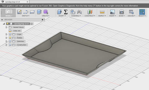
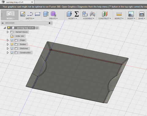
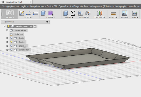
To create my serving tray, I first created a profile for the bottom surface. I then created an offset construction plane, raising it 20 cm above the bottom plane. I projected the bottom profile onto this new construction plane and used it as a guide to sketch out the profile for the top of my tray. Once the profiles have been created, I used the Create > Loft feature, selecting the bottom and top profiles to get the basic shape of my tray. To hollow out the tray, I used the Modify > Shell command, selecting the top surface of the tray and a hollow inside 2mm feature.
I found this feature of Fusion 360 (and Inventor) pretty cool, as it allows me to model more complex shapes. Good to know, so I have documented it here. You can also download my Fusion 360 source file at the end of this write-up and play through the process I used to create my model.
Making the Mold
My original idea was to use the standard vacuum infusion process to create my composite assignment. This is a pretty straightforward process, as we have a Composite Technology laboratory and we actually teach our students how to make composite parts using carbon fiber and vacuum infusion. For my assignment, I wanted to try something new, so I decided to create a 2-part mold instead, then use hydrostatic compression to make my composite part. If I'm successful, then this is something that we can easily replicate in our Fablab and satellite fablabs without the need for a specialised equipment and an expensive composite lab setup.
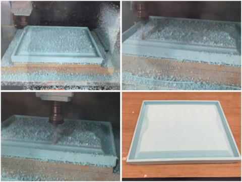
To create the mold for the outside surface, I started with the pre-hollow shell version of my model. I imported this model into our Roland MDX-540 SRP Player software, then re-oriented the model, so that the contoured surface was now the top profile for the machining operation.
Using the same approach as my Week 12 - Molding & Casting, I set up the stock (styrenefoam), type of milling (faster cutting, mostly flat planes, top only), created the tool path (top surface, cut area, depth of cut, type of tool and cutting parameters).
I did a 1.0mm surfacing of my workpiece first, then proceeded to machine my top surface. I started with a 6mm flat endmill, then worked my way down to the 3mm flat endmill, using partial cut area and cut depth. My reason for doing this is because the MDX-540 leaves a lot of surface uncut during the roughing operation when using a 6mm endmill.
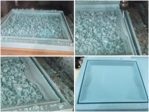
To create a maching piece for my compression mold, I started with a solid block in Fusion 360, with the same outside profile as my tray, then used the Modify > Combine > Subtract operation to get the required matching surface. I used this to machine the bottom half of my tray mold.
As in the top mold, I imported my 3D CAD model into the MDX-540 SRP Player, oriented my model correctly, selected styrenefoam as the type of stock and set up the correct stock dimensions. I set up the rest of the operations for type of milling, created the tool path and cutting parameters for the bottom mold and did a surfacing operation to level the surface of my workpiece.
Once this was done, I proceeded to machine the bottom half of my composite mold. The pictures below show the machining operation and the finished bottom mold.
Since I started with a 25mm thick blue foam, did a surfacing operation for both top and bottom molds and the height of each half of my mold was 20 mm, this meant that the top of my top mold was very thin, unlikely to be able to take the load from the compression molding. I therefore cut a piece of 5mm plywood and bonded it to my top mold using 3M VHB tape, to provide the structural support for the mold. I also tested the fit of the two halves. Since they were designed with matching dimensions, I found the fit of the physical molds very good.
Hydrostatic Compression Molding
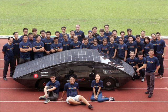
As mentioned earlier, SP has a Composites Technology laboratory in our School of Mechanical and Aeronautical Engineering, where students are taught how to do vacuum infusion of carbon fiber composite parts. I led our Solar Car team in the design and build of our solar cars, which participated in the 2013 and 2015 World Solar Challenge. The staff-in-charge of our Composite Technology Centre is a member of our solar car team and we also work very closely with the vendor who helped us fabricate the composite carbon fiber shell for our solar cars, so I have some experience with the vacuum infusion process used in our laboratory.
For this assignment, I wanted to try something different, using hydrostatic compression instead of vacuum infusion to create my composite part. I've heard Neil mention this technology during the 2015 and 2016 Fab Academy composite lecture, but have not had the urge to test it before, so I thought this would be as good a time as any. Some of the biggest advantages of using compression molding instead of vacuum infusion with sealant tape is that it is very easy to replicate in the field, even when there is no source of vacuum pressure or even electricity. There is no need for messy bleeder or breather material and a vacuum chamber to hold the excess epoxy extracted by the vacuum process.
For our solar car, we use a 1:1 ratio of carbon fiber + composite material to resin. I discussed this with our resin supplier and he advised that this is an ideal ratio, only achievable with a vacuum infusion process. For hand lamination, which I would be doing, from his own experience, the ratio would be more like 60 - 70% resin, with the rest being laminate material by weight.
I had a choice of 2 types of epoxy resins:
- 1. Epicote 1006: resin to activator ratio of 10:6, 30 min working time and 8-12 hrs cure time
- 2. Epicote 1003: resin to activator ratio of 3:1, 5-10 min working time and 2 hrs cure time
My plan for my composite serving tray was to use 3 layers of linen + epoxy, sandwiched between 2 layers of peel ply. This would be held in place between the top and bottom shells of my foam mold, with a hydrostatic weight place on the top of the entire assembly. I had also planned to use Epicote 1003 as my resin, with its shorter curing time, as I wanted to be able to quickly view the results of my tests.
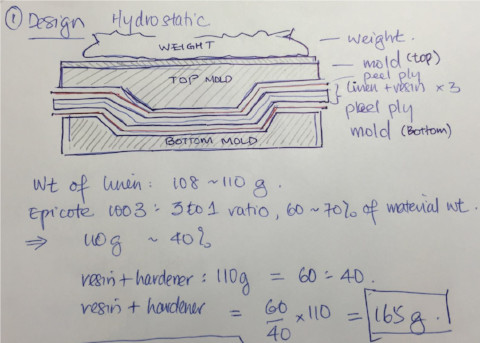
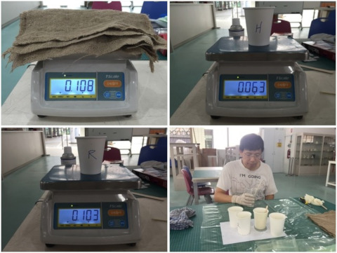
I first cut 3 pieces of burlap to the right size for my mold and weighed them. From the weight of the linen (108 ~ 110g), I computed the amount of resin + activator that I needed, using 60% resin/activator to 40% linen as the ratio. This gave me a resin/activator weight of 165g and 123g of resin to 41g of activator, since Epicote 1003 had a resin:activator ratio of 3:1.
Since Epicote 1003 had a very short working time of 5-10 minutes, I had to make sure that I had all the required material properly prepared and laid out. I also had to rehearse the procedure mentally, to make sure that I was very familiar with all the steps required. To facilitate my preparation, I made a list of all the steps in the workflow to create my composite part:
- 1. Cut burlap
- 2. Weigh burlap
- 3. Calculate resin:hardener requirements
- 4. Assemble material:
- peel ply x2 pcs, pre-cut to size
- burlap x3 pcs, pre-cut to size
- apply mold release wax to top & bottom molds
- prepare 2 sets of cups each, for resin and activator (2 sets because 1 set would be used to scoop the resin and hardener from their respective containers
- prepare mixing containers
- prepare applicator/brush and sticks for stirring
- lay out top and bottom molds (wax applied)
- prepare trashbag of water as hydrostatic weight
- prepare MDF boards to place above molds as base for hydrostatic weight
- 5. Lay peel ply over top and bottom molds
- 6. Weigh out resin (123g) and hardener (41g)
- 7. Pour resin into mixing container, followed by hardener. Mix well.
- 8. Spread resin on burlap layer 1. Use stippling motion to make sure that resin penetrates & wets the burlap. Lay wetted burlap over peel ply on bottom mold.
- 9. Repeat for burlap layers 2 and 3.
- 10. Lay peel ply over topmost burlap layer.
- 11. Lay top mold over the composite layers.
- 12. Stack MDF, followed by hydrostatic weight over assembly and record the timing.
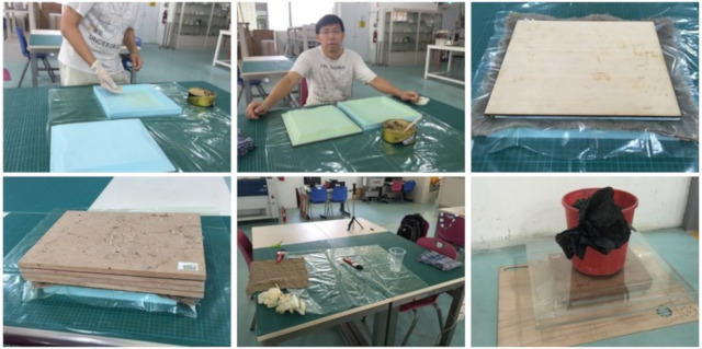
I've attached a snapshot of the handwritten copy of the workflow that I made to show my thought process. The eagle-eyed would be able to spot that after going over the process mentally, I had a change of heart and decided to use Epicote 1006 instead of 1003.
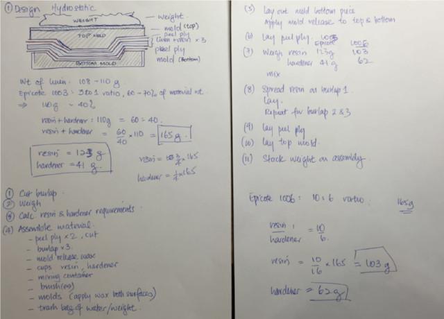
I was comfortable with my overall plan. The one step which I was unsure of was how long it would take me to apply the resin mixture over the burlap layers. In the worst case scenario, I had to apply the resin mix on 3 layers of burlap in 5 minutes, which works out to 1 min 40 sec per layer. Since I was working with a totally new epoxy mixture and new material (burlap), I was somewhat uncomfortable with the very limited time, so I decided at that point to go with the Epicote 1006 instead.
I recalculated the amount of resin and activator that I needed for Epicote 1006 and came up with 103g of resin and 62g of activator as the required amount.
Once the choice of resin was decided, I proceeded with the activites as listed in my workflow. I applied mold release wax to the top and bottom molds, prepared the burlap and peel ply layers, measured the amounts of resin and activator required and kept them in separate cups.
I then poured the resin, followed by the activator to my mixing cup, taking care to make sure that I left minumum amount of each in the holding cups. I stirred the mixture gently for about 5-6 minutes, then left it to stand for another 4-5 minutes. I could see a small amount of minute air bubbles, but the mixture was generally clear.
I applied the resin mixture to my first layer of burlap, taking care to ensure that the burlap was completely wetted, using a stippling motion for good penetration of the linen. The wetted burlap was placed over the peel ply on the bottom mold. I did the same with burlap layer 2. At this point, I ran into a snag - my resin mixture was finished! The burlap absorbed a lot more resin that I expected, based on my experience with carbon fiber composites. Even though I had allocated a higher amount of resin/hardener mix than for carbon fiber using vacuum infusion, it was insufficient. Rather than re-weigh and mix a new batch of resin/hardener, I decided to leave it at 2 layers and learn from the experience for the next time I work with burlap.
I completed the layup process by adding another peel ply layer over burlap layer 2, followed by the top mold. MDF boards were then stacked over the composite assemby and my hydrostatic weight (trash bag filled with water) placed over the MDF. The MDF boards were used in order to create a larger surface for the hydrostatic weight to sit on. The entire composite assembly was placed in a corner of the Fablab while waiting for the resin to cure. The worst case time required for curing was 12 hrs, which meant that my "masterpiece" would be ready for checking the following morning.
Results
I returned to the Fablab very early the following morning, as I was very eager to see how my compression molding process turned out. I set up my tripod and camera, as I wanted to capture the moment. It's probably the first ever instance of compression molding done in SP. All of our composites work so far has been done using vacuum infusion, so I was treading on uncharted territory, as far as SP was concerned.
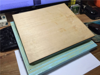
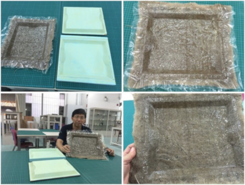
I removed the pail of water, which I used as weight for my compression molding, followed by the acrylic and MDF boards. Cue drum roll.... cue 15 seconds of extreme silence... I removed the top mold and picked up my molded composite piece, which came off the mold very easily. I was pleasantly surprised as the composite serving tray came out rather well. One of my concerns was that I did not have sufficient resin mix to make a proper composite piece. The tray was quite rigid and firm, despite having only 2 of my intended 3 layers.
The pictures below show the results of my compression molding process. I only need to trim off the excess edges and I would have my serving tray. There are improvements that I can make to the finishing of the composite tray, but I'm in two minds about it. One the one hand, I would like to keep it as it is, for historical & sentimental reasons and make another better composite tray, using the experience that I have gained from making my first tray. My molds are still in perfect condition, so it would only take me another hour or so to layup another composite tray.
At the same time, I would like this tray to have a better quality finish, something that can be easily fixed...
Reflections
I wish I could say that my entire assignment proceeded smoothly from start to finish and that my composite serving tray came out perfect and could not be improved upon. That only happens in dreams, seldom in reality, especially not when so many firsts (at least for me) are involved. There are still many aspects of my workflow that could be improved upon and I have gained a lot from doing this assignment.
During the design process, I learned to make use of some additional features of Fusion 360. I was stuck intially on how to create a hollow shell. Once I discovered how easy it was to create a shell, I felt somewhat stupid, for having missed the obvious.
During the machining process for my first mold, I secured the workpiece to the bed using double-sided tape, which is our usual practice for blue foam. However, I did not check on the condition of the tape - which was bought sometime ago. Even though it was a fresh roll that I opened a few days previously, it had lost most of its adhesive strength. The surfacing operation went well. However, during the roughing operation, the workpiece detached and I shut down the machine. Nothing serious, but one piece of blue foam ruined.
I decided to use 3M VHB, which we had in our Fablab instead. These tapes were purchased as part of our solar car project and are used to tape our solar panels to the body of the solar car. After my experience with the blue foam detaching, I decided to put many strips of VHB tape across the entire length of the foam. It stayed secure during the milling operation, but removing it was another matter altogether. Learning from this experience, I used the VHB tape sparingly when milling my next piece of foam.
I'm still learning the intricacies of the SRP Player for our MDX-540. I've gone beyond what was covered during the Roland training, but I feel that I can still optimize my settings, in order to reduce the time required for my cutting operation. This is one area which I want to pursue further.
For the compression molding process, I still have not gotten the right ratio of resin/hardener mix to fabric. The burlap cloth that I used is very absorbent. The current ratio is something like 165g of resin to 72g of burlap. I did not manage to cover each piece of burlap completely and some areas of the composite surface is a bit patchy. This can be easily fixed by applying another layer of resin, but I would rather get it right the first time round.
I also found it quite difficult to apply the resin to the burlap using a paint brush. Perhaps using a linoleum roller or squeegee might be more effective? This is another thing which I need to experiment with, in order to determine the best method of applying resin to burlap.
All in all, I really enjoyed this assignment, the new knowledge and skills which I have acquired. It gives me great personal satisfaction to be able to challenge myself, to venture into new areas and improve on my existing knowledge.
This is also my last outstanding assignment for the Fab Academy diploma course. I have actually attempted, mostly successfully, some not so successfully many other things during the assignments in other weeks. I have only managed to document a fraction of the things that I have done and there is still so much more that I want to do and discover. I hope to be able to keep active in the Fablab community and to be able to give back to the community in the same way that I have learned from the work and efforts of others in the community.
Thanks a lot Neil, Fiore, Bas and others in the Fablab network for the wonderful work that you are doing. You will always have my gratitude and appreciation.
Downloads
The Fusion 360 files for my serving tray design can be download using the link below. I have also provided the STL version of my file for convenience.