Exercise 07 - Computer Controlled Machining
Assignment
Our class assignment for this week is "Make Something Big" or more accurately, large format machining.
For this assignment, we have to familiarise ourselves with CAD modeling and the workflow involved in producing the part on a large format router. I took a step back and reflected on the processes involved. I first needed to decide what I wanted to make, design it in a CAD package (which package), understand all the terminology involved in machining operations, such as feed rate, chip load, flat vs ball-nosed endmills, intepreting g-code and the operation of the Signvec SK2030 router that we have in our fablab.
Determining Press-fit for the Material
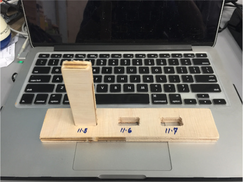
I started off by measuring the thickness of the 4'x8' plywood sheets that we ordered for our Fablab. These were nominally 12mm sheets, but the measured thickness was closer to 11.5mm. My colleague, Hendra, wrote a simple g-code program in DXF2GCODE, to determine the settings for the best press-fit for our material.
Hendra's program created a series of rectangular holes with sizes ranging from 10 to 12mm in 0.5mm increments. The results of his testing is reproduced here:
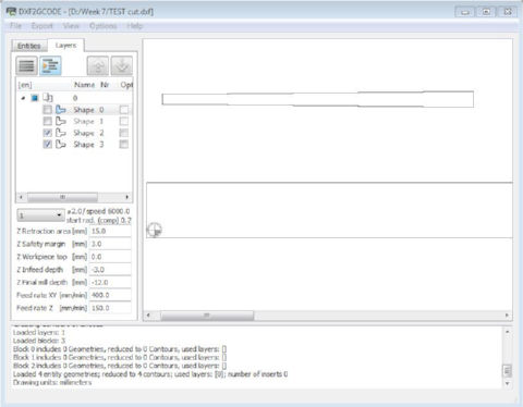
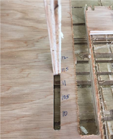
Based on the results from Hendra's test, I decided on slot sizes of 11.5mm for my design.
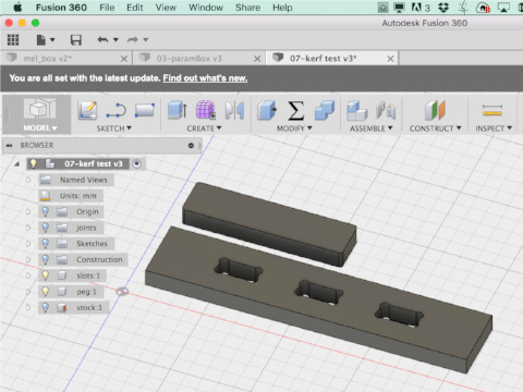
I subsequently designed my own model for testing the best settings for my press-fit furniture in Fusion 360. For my press-fit test, I made slots of 11.5mm, 11.6mm and 11.7mm. I obtained the most snug fit with the 11.5mm slot. The other 2 settings, 11.6mm and 11.7mm were still usable, with reasonably good fit, with perhaps a bit more wriggle room when using 11.7mm cutouts.
Flatpack Stool Design - Ver 1
I decided to make a flatpack stool as my first foray into large format machining, as CNC is not really my forte and I wanted something manageable, while I got familiar with the workflow. As I gained experience, I hope to be able to venture into flexures and living hinges based products.
For my first design, I decided to make use of SketchUp, rather than Autodesk Inventor, as I wanted to use something that is cross-platform (Windows and OSX in this case). SketchUp Make is available for free and there are lots of plugins and extensions which adds functionality to the core product. SketchUp is also a favorite of woodworkers, at least based on what I was able to glean while researching the topic. The added bonus is that it is a very simple program to use.
Once the choice of software had been decided, I proceeded to design my stool. I first made a 3D model and assembled it in SketchUp, to make sure that all the parts would fit. From here, I made a copy of my model, broke up the copy into its component parts, e.g. seat, legs, and laid them flat on another part of the workspace, ready for export to dxf.

There at least 3 ways of going from a SketchUp design to CAM process that I am aware of, based on my research on the Internet:
- 1. Export file to dxf and import it into CAM program
- 2. Use SketchUCam to generate gcode and send to CNC machine directly
- 3. Use FlightOfIdeas plugin to convert faces to SVG outline, import to MakerCAM, generate toolpaths for CAM and send to CNC machine
I decided to go with the first approach, i.e. generate dxf from my SketchUp model, then import it into the CAM program that we use here in SP, to generate the toolpath for routing. My workflow then was as follows: SketchUp > dxf > Mastercam > gcode > JG > router.
JG is a software that came with our large format router, which translates generic gcode to a format that the machine understands.
Feeds & Speeds
For any milling or routing operation, it is important that the right parameters are selected for the machine, the tool used and the type of material that is being cut. The relation between these various parameters is best described by an equation:
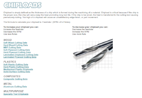
chip load x cutter diameter x #flutes x spindle speed = feed rateThe CNC Cookbook website has a very good description of the interplay between these various factors, with wrong settings leading to various problems, such as tool breakage, poor surface finish, poor tool life, machine chatter and material removal rates.
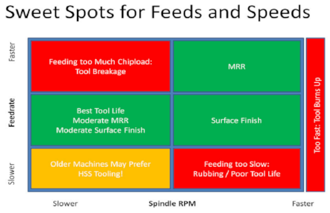
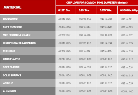
Onsrud has a very good reference for the cutting data for different types of materials. The material that we are using for our Make Something Big assignment is soft plywood. From information in the table and other references on the Internet, a good starting point for our CNC with a 6mm (1/4") endmill would be a feedrate of between 700 - 1000 mm/min. Online and mobile based apps are available for calculating feeds and speeds for various materials.
Mastercam Toolpath Generation
The CAM workflow for Mastercam is as follows:
- 1. Open the design file.
- 2. Click Zoom > Fit icon to display the workpiece on the screen.
- 3. Set System color (red) and level number (100).
- 4. Select curve(s) on the workpiece.
- 5. Create a bounding box around the workpiece.
- 6. Move the workpiece to the Work Coordinate System (WCS) origin.
- 7. Set Level 100 as main level and select Machine Type > Mill > Default.
- 8. Create Toolpath, enter name of the EMC filename for saving.
- 9. Select Chain, select the curve/profile, toolpath type and tool from the library.
- 10. Set the tool and cut parameters, stock information.
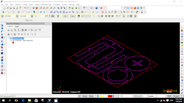
- 11. Use Mastercam Simulator to verify the cutting operation.
- 12. Repeat 8 - 11 until all curves/cutting operation has been selected.
- 13. Click All operations icon, select Post selected operation icon to generate the NC file. Save the file.
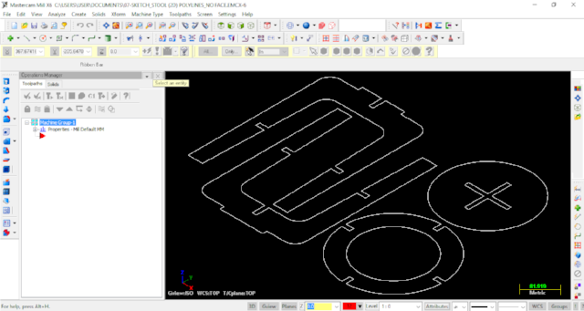
1 Importing dxf file |
 2 Creating bounding box |
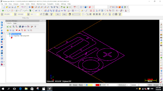 3 Setting origin |
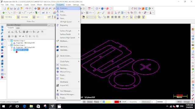
4 Select Toolpath Contour |
 5 Contour operation |
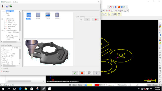
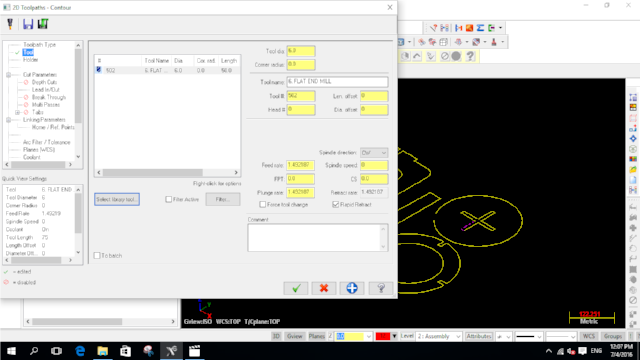 6 Tool parameters |
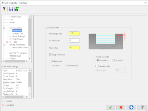
7 Cut parameters |
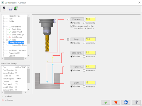 8 Linking parameters |
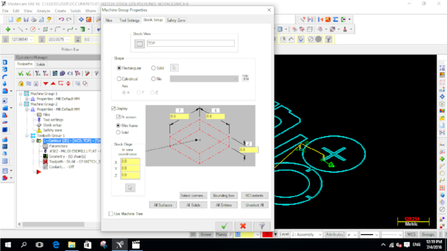 9 Stock setup |
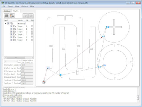
Besides Mastercam, there are other ways to generate the machine toolpath. DXF2GCODE, a free software downloadable from Sourceforge, is a good example. DXF2GCODE reads in a dxf file and generates optimized toolpaths based on the configured cutting parameters.
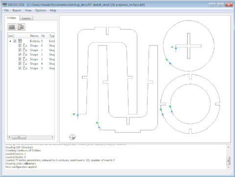
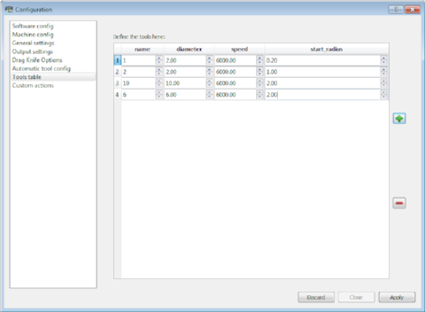
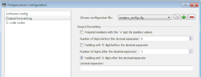
Users can customise DXF2GCODE by selecting the Options > Configuration or Options > Post Processor configuration menu option. For instance, I added a 6mm mill bit to the list of available tools, under the Options > Configuration > Tools table section.
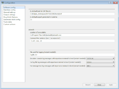
The correct endmill is selected from the Layers tab. This is also where you set the milling parameters for the CNC. Once this setup is done, you can generate the correspondig gcode by selecting Export > Optimize and Export Shapes. The generated gcode is then loaded into the CNC_CHANGE (JG) program for our Signvec CNC router.

CNC_CHANGE (JG) Program
The JG program is very very particular about the formatting of the gcode that it reads. For instance, I have no difficulty viewing the generated gcode in most other gcode viewers, e.g. JNC viewer. However, JG gave me a totally messed up toolpath instead. To compound matters, documentation for the Signvec SK2030 and the JG program is almost non-existent.
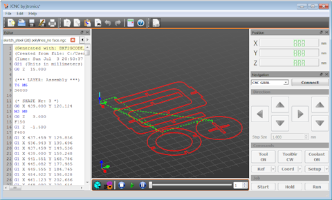
After a fair amount of frustration and hair pulling, I realized that the problem was caused by the spaces between the X, Y, Z, I, J and K parameter and their corresponding values. The solution to this is to remove all the whitespaces using a texteditor like notepad or gedit. Removing spaces from a few hundred to a few thousand lines of gcode is extremely tedious. I decided to explore the DXF2GCODE program in more detail and discovered that I could actually configure the Post Processor to automatically remove the blank spaces for me.
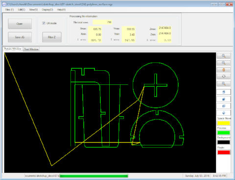
The resultant gcode file, read in by JG, after removing whitespaces:
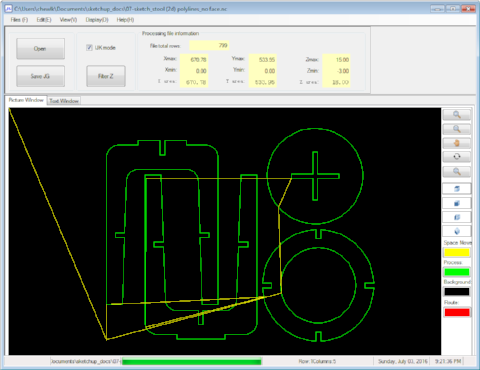
Once the gcode has been verified by JG, it is then saved as a .JG file, ready for cutting on the Signvec SK2030.
Milling the Flatpack Stool - Ver 1
The Signvec CNC is controlled via a 3.5 inch jog-shuttle controller. The JG file prepared earlier is copied over to a USB flash drive and plugged in to the SK2030 jog controller. Pressing the F1 key bring up an online help screen. Pressing F4 allows you to load the gcode file from the USB drive.
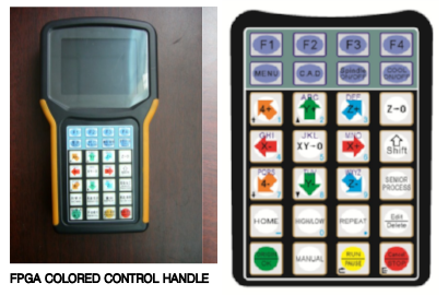
Once the file is selected, pressing the OK button will read the file. At this point, the machine parameters can be changed/set by pressing the Edit key, followed by the new values for that parameter. Pressing the OK key registers the new settings.
Pressing the X, Y or Z keys moves the spindle in the respective directions. The XY=0 key is used to register the XY origin in the User Coordinate System (UCS). Pressing the Z=0 key registers the Z origin in the UCS. Pressing the Spindle On/Off button allows one to turn the spindle motor on or off. This is useful when setting the Z origin. When positioning the head, the High/Low key toggles between high speed and low speed movement. Pressing the Run key, followed by the OK key executes the selected cutfile.
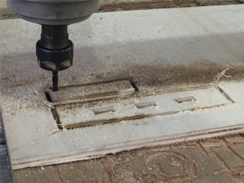
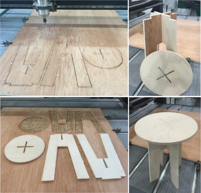
After setting the UCS XY origin for my workpiece, I first did an air-cut to verify the proper operation of the CNC and to check my workpiece boundaries. I then moved the spindle to an unused area of the board and moved the head down to register the actual Z origin, which is the top surface of my stock. Once I was satisfied with my cutfile, I proceeded to route my flatpack stool. Tabs were added to the gcode to hold the pieces in place during the milling operation.
During milling, pressing Shift-F2 or Shift-F3 allows one to decrease or increase the spindle motor speed by 3000 rpm each time. The SK2030 spindle motor has a range of 6000 - 24000 rpm. Pressing the UP-arrow (Y-up) or DOWN-arrow (Y-down) keys during milling changes the feedrate by 5% each time. The feedrate can be varied between 50-120% of the preset feedrate.
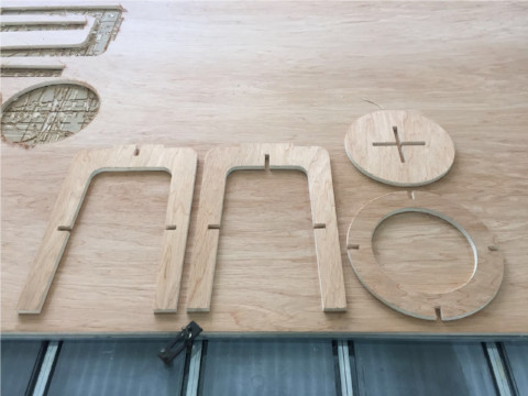
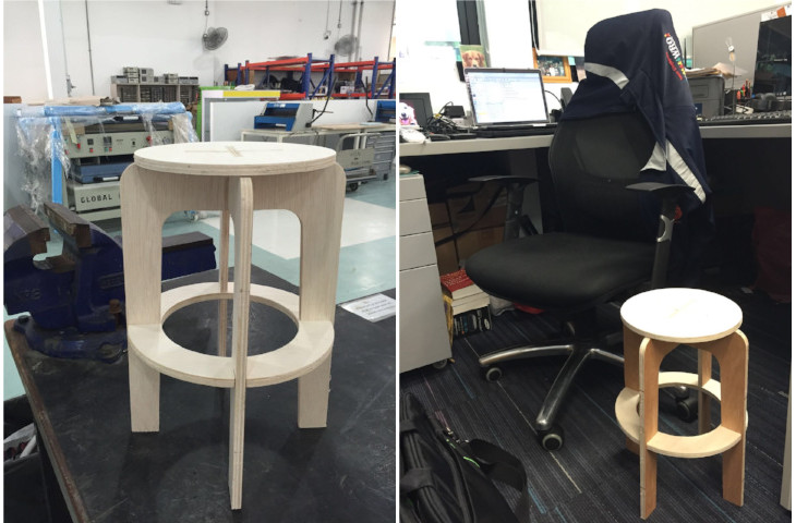
Once my stool has been cut out from the stock material, the tabs were removed using a hammer chiesel/screwdriver combination. The milled pieces were then sanded down to clean up the edges from the milling process. The stool was then assembled.
Problems/Issues
I encountered a number of problems/issues in designing and making the first version of my flatpack stool. I opted to use SketchUp to design my stool and export it to dxf using the dxf/stl plugin. What I didn't know was that SketchUp exported a 3D version of the dxf file. When this file was imported into Mastercam, there was a lot of cleaning up to do. The second problem I encountered was that the dxf file consisted of multiple short line segments, including those for the circles and curves. Again, this meant a log of clean-up was required. Rather than doing the clean-up in Mastercam, my dxf file was opened and cleaned in Autocad.
Mastercam is a very powerful CAD/CAM software with a long learning curve. Unfortunately, the software was installed in the PC that was meant for the Signvec SK2030 use - which meant that access to the machine was limited during this assignment. Students & staff from our Mechanical Engineering school could access the software via our campus network, but as EEE staff, I had no access to the software, apart from the system installed on the Signvec PC, which made learning the software difficult.
When I designed my stool, I opted not to add in the dogbone fillets, as there were a number of them to add and I basically took the easy way out, thinking that I could just shave off a bit of the wood after the milling operation. This meant that my stool had a less than perfect fit. Another major design flaw was the circular ring supporting the legs of my stool. Drawing and assembling it in SketchUp was very easy. I thought that I could just tilt the ring and jiggle it around to assemble it in the actual piece. What I found was that the fit was so tight that there was no way for me to assemble the ring support element without breaking apart one of the stool legs.
All in all, I found this assignment a very good learning experience for myself. It definitely took me out of my comfort zone and forced me to learn a lot of new software and the CNC router, something which I would otherwise not have done on my own.
In retrospect, I could have just used DXF2GCODE directly, rather than going the Mastercam route, as I could have achieved the same end result, but with a lot less effort.
Downloads
The design files for version 1 of my stool can be downloaded using the links below.
- SkechUp file for flatpack stool (ver 1)
- Cleaned up version of dxf file
- Gcode generated by DXF2GCODE, suitable for JG program
- Fusion 360 file for press fit test
Updates
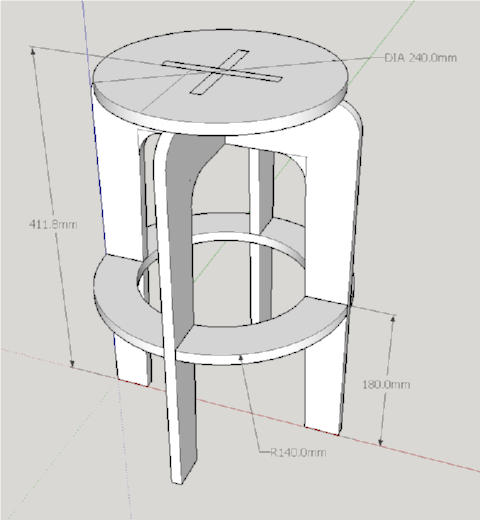
I subsequently revisited this assignment and decided to design another version of the flatpack stool, this time using Fusion 360. My decision to use Fusion 360 is because the CAM component is integrated as part of Fusion 360 and it makes generating gcode for manufacturing a lot more convenient. The software is also somewhat similar to Autodesk Inventor, which is an added bonus for me, because it is equivalent to learning 2 software in learning 1.
Version 2 of my flatpack stool is shown in the figure below. My entire design process can be played back in Fusion 360. Fusion 360 has a addin to generate dogbone fillets written by Casey Rogers, which makes creating these items very convenient. You simply select the vertical lines in the CAD model where you want the dogbone to be added and click on the OK button to add it in.
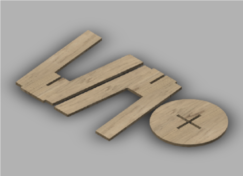
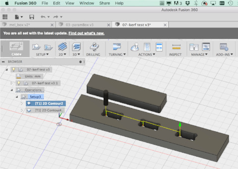
Fusion 360's CAM process has a built-in simulator, which allowed me to verify the machine toolpath and milling operation. I could also specify the entry points and where I wanted to insert tabs for the parts I am milling. Similar to the process for Mastercam, I set the UCS XY origin at the bottom left corner of my stock and the Z-origin to the top of stock. I added a 2mm offset to the bottom of my stock and instructed the CAM process to mill all the way through during contour operation. This ensures that the workpiece is completely cut through and handles slight variation in the height of the plywood sheet.
For the CAM process, I set the feedrate to 500 mm/min and spindle speed to 8000 rpm, which gave me a chipload within the recommended limits. However, my settings were over-ridden by those set in Signvec's jog controller. Fusion 360 has a wide selection of machine configurations for CAM post-processing. Initially I selected generic grbl, as Signvec machines are not in the list. Just as in the case of DXF2GCODE, this setting gave me totally messed up toolpaths in the JG program. By selecting generic Mach3 instead, the problem was resolved.
I also found it helpful to create guide holes in my stock in Fusion 360, avoiding areas occupied by my workpieces. Once the guide holes have been marked out, I used an impact driver to put in self-tapping screws to hold the plywood sheet firmly down to the sacrificial board.
Click on the hyperlink to download the Fusion 360 design file for my Flatpack stool version 2. You can play back my entire design process in Fusion 360. The CAM settings are also in the same file.