Exercise 05 - 3D Scanning & Printing
Assignment
There are 3 parts to the assignment for this week:
- 1. Test the design rules for our 3D printer(s) - group project
- 2. Design and 3D print an object (small, few cm) that could not be made subtractively
- 3. 3D scan an object (and optionally print it)
SketchUp
To create the 3D models for 3D printing, I decided to use SketchUp. I had previously used SketchUp back in 2014, to make simple 3D models, so I thought this would be a good opportunity to revisit the software and see what additional features SketchUp has added since then.
The current release is SketchUp 2016 and is available on both the Windows and OSX platforms. Unfortunately, there are no versions for Linux, though earlier releases could run under Wine. SketchUp is available as a free version (SketchUp Make) and a paid version (SketchUp Pro), available in both 32- and 64-bit release.
I tried installing the 64-bit version of SketchUp Make on my Ubuntu machine using Wine, but could not get it to run. After trying for a while, I decided to give it up and revert to the versions on Windows and OSX, which ran without any problems.
SketchUp supports extensions written in Ruby, available from the Extensions warehouse. To download SketchUp extensions, you must be a member. Free membership is available.
Some of the most popular SketchUp extensions for 3D printing are:
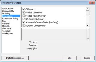
The first 2 extensions allows the use to export SketchUp skp models to STL files for 3D printing. The Solid Inspector extension has the ability to automatically repair many manifold problems. The CADspan plugin contains a set of tools to help the user make the SketchUp model 3D printable, such as organizing layers to separate sections, unsmooth the model or plan tolerances.To install an extension in SketchUp, select Window/Preferences/Extensions and click on the Install Extension button, then select the extension to install.
There are a number of good tutorials and references to using SketchUp and using SketchUp for 3D printing. Some of the tutorials that I've used are:
- SketchUp School - 3D Printing Guide
- 8 Tips for 3D Printing with SketchUp
- Basic Workflow for 3D Design in SketchUp - Instructable
- SketchUp Tutorial for 3D Printing - from All3DP
The 8 Tips article lists some very important points when creating models for 3D printing:
- 1. Models have to be solid (all faces closed) to be 3D printable
- 2. Give your walls thickness
- 3. Scale up by 100 (or 1000) to make small parts
- 4. Increase circle/arc segments to get smooth curves
- 5. Model parts as separate components & use Outer Shell to combine
- 6. Use plugins to work faster (see above for useful plugins)
- 7. Know the print material specifications & limitations
- 8. Reduce material to reduce cost - especially true when using commercial 3D print service
Points 1 & 2 above are very important when designing models for 3D printing. Point 1 is also known as the manifold or "watertight" test - all faces of the 3D model must be closed. This is where the Solid Inspector plugin comes in very handy. Solid Inspector makes inspecting the 3D model for closed surfaces and fixing problems very simple. Another alternative is to export the model to STL and check for manifold errors with Meshmixer or NetFab.


Another point that is very important is that all vertices/faces must be oriented correctly, i.e. they must face the same direction. When designing 3D models, a common error is to have some of the faces pointing inwards and others pointing outwards. This confuses the 3D printer. Solid Inspector also checks for and fixes these errors.
Testing Wall Thickness
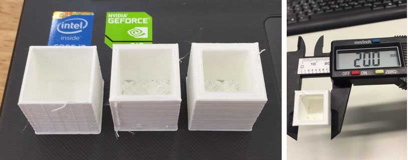
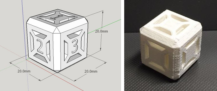
My first test for 3D printing was to determine the optimal wall thickness for my 3D models. I created 3 simple 20mm x 20mm x 20mm cubes in SketchUp, with wall thicknesses of 1.0mm, 2.0mm and 3.0mm, checked the models using Solid Inspector, then exported them to STL format.

Printing 3D Model
We have a number of different types of 3D printers in Fablab SP. Our main 3D printers are Ultimaker 2s, Makerbot Replicator 2s and Up Plus. Since I work mainly with the Ultimaker 2s, I imported my "wall thickness" STL file into Cura, the 3D print software for the Ultimaker 2.
I prefer to work in the "Full Settings" mode, switching occasionally to the "Expert Settings" mode, when I need to tweak the 3D printer parameters further. For this test, I used mostly default settings, just changing the layer height to 200 microns (for faster 3D print), nozzle size to 0.4mm, shell thickness to 1.2mm (multiple of nozzle size) and fill density to 15%.

The optimum wall thickness depends on a number of factors, such as type of material, structure and design of the 3D model, vertical or horizontal wall. The I.Materialise and Shapeway websites have very good write-ups on how to choose the right minimum wall thickness. For example, Shapeways recommends a minimum wall thickness of 2mm even though you could use a 1mm minimum wall thickness when using their white, strong & flexible plastic material.
During my tests, I found that my cube model with wall thickness of 1.0mm, 2.0mm and 3.0mm all printed out successfully for PLA, so wall thickness wasn't an issue. I would size the wall thickness based on the type of material, the design of my 3D model and the purpose of the structure.
Tolerance
For the tolerance test, I decided to create a 20mm wireframe cube with a shaft passing through one axis. I designed hole with a diameter of 10mm and the shaft a diameter of 8 mm, so that there is a 1mm clearance all around the shaft. The entire 3D model was printed without any supports. There was hardly any excess PLA filament material deposited between the shaft and the hole, so the 2 structures were separate by applying just a small force and thereafter turned very easily.
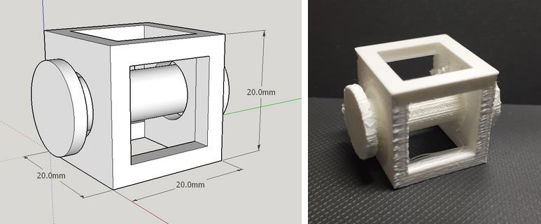
I found that the Ultimaker 2 printed objects to the designed size very accurately, so a 1mm gap alround between the hole and shaft made the mechanism too loose. My next test would be to reduce the gap between the hole and shaft to 0.5mm alround and reprint the 3D model to see if it will still be easy to separate the shaft from the hole and if the structure will still turn easily.
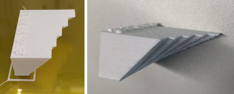
Overhang Angle Without Support
To determine the overhang angle that our Ultimaker 2 can print without any support, I decided to create my on 3D model in SketchUp, with angles from 40 deg to 60 deg, in 5 deg increments. The recommendation for most 3D printers is a max angle of 45 degrees without the need for support. My test results show that the Ultimaker 2 can easily handle printing up to a 60 degree overhang without any support.
Percentage InFill
My colleague, Mark Ng did a very detailed analysis of the effects of the amount and type of infill on a Makerbot Replicator 2 3D printer. The link to his test results is available here. I'm interested in finding out how the Ultimaker 2 performs compared to the Makerbot Replicator, so I will conduct a similar test and post my results here as well.
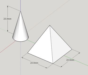
Printing Sharp Points
To test the ability of our Ultimaker 2 3D printers to handle sharp points, I decided to print a cone and a square pyramid structure. The SketchUp model of the test is shown below. The 3D print results and my observations will be updated later.
Bridging without Support
Based on the 3D printer test model that I downloaded from Thingiverse, the Cubion 3DP-110F can bridge gaps of up to 16mm without any support when using ABS material. I ran the 3D printer test model which I downloaded from Thingiverse on one of our Ultimaker 2 3D printer. The detailed results are in the next section. What I found was that the Ultimaker 2 had no problems bridging gaps of up to 16mm in all my test configurations.
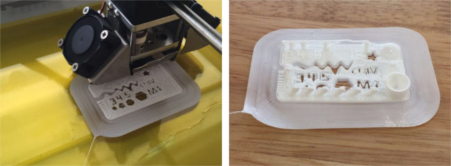
3D Printer Test Model (Thingiverse)
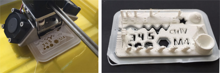
I started off by designing my own 3D models to test each parameter for 3D printing one at a time, such as wall thickness, max angle without support. Thingiverse has a number of ready models that test various aspects of a 3D printer. One of the best all-in-one 3D printer test models that I have come across is the one designed by CtrlV. His model test many of the important parameters for a 3D printer, such as size (accuracy), hole size, nut size, fine details, rounded print, minimum distance & walls, overhang angle, bridge print and surface. CtrV's test model can be download from here.

The image above was printed on a Cubicon 3DP-110F, a 3D printer from Korea. The printer has a build volume of 239mm x 190mm x 200mm and a heated, completely enclosed build volume, unlike most other 3D printers in its class, which have an open build volume. It is also one of the more expensive 3D printers in its class, retailing for GBP1899.
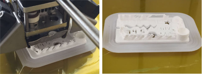
I decided to run the 3D print test on the Ultimaker 2 that I have been using an determine the optimal setting for the printer. To do this, I started with the "Quick Settings" menu option on Cura, then switch over to the "Full Settings" mode and adjusted the settings to get a better print result. I also adjusted the extruder temperature on the Ultimaker and this can only be done from the device LCD front panel.
I started with the current default configuration on the 3D printer and selected the "Fast Print" setting on Cura, loaded the STL file, generated the gcode and saved it to SDcard. From there, it's off to 3D print the test file.
Most of the features on the test print came out, but I found that there was too much stringing and the bridging to be too thin at Fast Print setting. The Fast Print setting used 10% infill, 50 mm/s print speed, 150 mm/s travel speed and 150 micron layer resolution.
My next test was to print the model using the Normal Print setting. This printed the model with 20% infill, 50 mm/s print speed, 150 mm/s travel speed and 100 micron layer depth.
At Normal Print settings, there was way too much stringing and many of the features were merged together. At this point, I suspected that some of the current settings on Ultimaker was not too right. The main culprits for excessive stringing are too high a temperature and too slow a print speed, so I decided to check the settings on the printer - what a shock! The nozzle temperature was set to 240 degC, which was way too high for PLA! This temperature is more suited for printing ABS material.
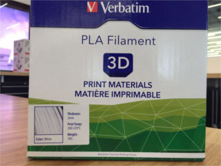
A quick check on the box for our filament confirmed my suspicions. We use Verbatim 3D filament and the recommended temperature setting for Verbatim PLA is between 200 - 240 degC.
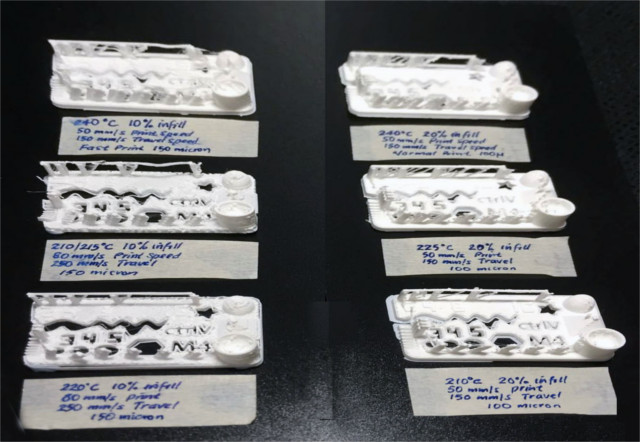
I started to vary the nozzle temperature, the percentage infill, print and travel speed, to try find the optimal setting for our Ultimaker 2 with Verbatim PLA. With the correct settings, the Ultimaker should be able to print a model with minimal stringing, bridge the 16 mm gap and print all the features on the test model with minimal "smudging".
A compiled summary of my tests is shown in the picture below.
Optimal Settings for PLA
Based on the series of 3D print tests that I carried out, the optimal setting for that Ultimaker 2, with Verbatim PLA material is:
- Nozzle temperature: 210 degC
- Percentage infill: 20%
- Print speed: 50 mm/s
- Travel speed: 150 mm/s
- Layer resolution: 100 micron
At 150 micron layer resolution, 10% infill and nozzle temperature of 220 degC, I found that some of the features on the 3D model did not print out correctly. The model was also too flimsy. I suspect that this is largely due to the very small features on the 3D print test model. If the features were larger, it would have printed out correctly.
Optimal Settings for ABS
I did a similar test on another of the Ultimaker 2 3D printers that we had in our Fablab, this time using ABS filament from another vendor. Using a similar approach to that used for my PLA filament test, I found that using the following settings for ABS produced a decent print:
- Nozzle temperature: 230 degC
- Percentage infill: 20%
- Print speed: 50 mm/s
- Travel speed: 150 mm/s
- Layer resolution: 150 micron
3D Model for Assignment
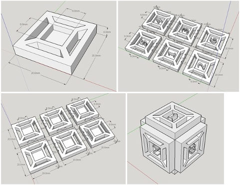
For the 3D print assignment, we have to design a print a 3D model which cannot be manufactured using subtractive manufacturing. I decided to design a hollow dice for this assignment. My model was inspired by the "thorn dice" created by Chuck Stover. My dice are nowhere near as elegant as those by Chuck, but it's a start. I'm not completely happy with my results, so I will be redesigning my dice as 6 separate faces, then assembling them in SketchUp and putting a sphere inside the hollow space created.
Since I couldn't get the number imprints on the surface of my hollow dice, I decided to redesign my dice and print it out again, this time in ABS. To create my new design, I started with designing one face in SketchUp, then replicated it 5 times to get the 6 faces. I created the numbers using the pull command to create a depression for the numbers, then putting in the numbers using the 3D text feature. Next was to rotate the faces and align them to get my cube. To give the dice a nicer appearance, I created a chamfer along all the edges and closed up the corners.
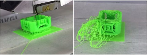
I encountered a number of problems/issues when I tried to print my hollow dice on our Ultimaker 2:
- the filament was not feeding smoothly, grinding of the filament
- bottom chamfer section did not print out as there was no support and no wall thickness
- model adhesion to the platform was poor - we used masking tape, which didn't stick very well to the build platform. One of my jobs completely detached from the platform, resulting in a mess during printing
- print settings which worked a few days ago no longer worked
To fix the problem in my design, I created a wall thickness for my chamfered edges, rather than using just the skin. Masking tape is not a good solution for the build platform. We will need to revert to using hairspray, glue-stick or kapton tape. Singapore has a very high humidity (>90%) and we believe it is affecting the filaments which are left on our 3D printers. We are exploring storing our 3d printer filaments in a dehumidified environment until they are required. Another alternative is to move the 3D printers to an air-conditioned environment. The filament feeder is one issue that has troubled us from the start. We are working with our vendor to resolve this, but have yet to find which really works. Cost/quality of filament is not the issue, because even Verbatim & Ultimaker's own filament fails to feed due to grinding.
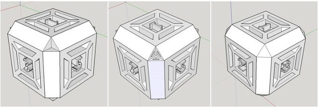
My redesigned hollow dice model is shown below. I've added a 0.7mm wall thickness to all the chamfered edges, which solves the problem of air-print along the bottom face. Another improvement would be to add small supports under the top face, in order to reduce the distance that the 3D printer has to bridge.
Another object that I would like to print is the sphere embedded within a wireframe cube. I have previously designed the 3D model in Tinkercad, OpenSCAD and Antimony during Week 2 - Computer Aided Design. I'll use one of the models from Week 2, generate the STL file and 3D print it.
Hollow Dice 3D Model
My hollow dice 3D cad model is displayed below. You can zoom the model by using the scrollwheel on the mouse. To rotate the model, click and drg the left mouse button.
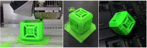
Some of the problems that I encountered in printing my hollow dice and the final good print are shown below.
The files that I used in my 3D print testing and assignment can be downloaded from the links below:
- Wall thickness model
- Tolerance model
- Overhang model
- Cone-pyramid model
- Thingiverse 3D Printer test model
- Hollow dice model
3D Scanning - 123D Catch
Autodesk 123D Catch is a free app that uses photogrammetry to create 3D models from a series of photographs. The photographs can be captured using a mobile device or any camera and 3D models that are created by this software can be printed on a 3D printer. It is available on the OSX, Windows, IOS and Android platforms. The program is available from the 123D website, Apple's AppStore, Google Play, Windows Store or from http://www.123d.com.
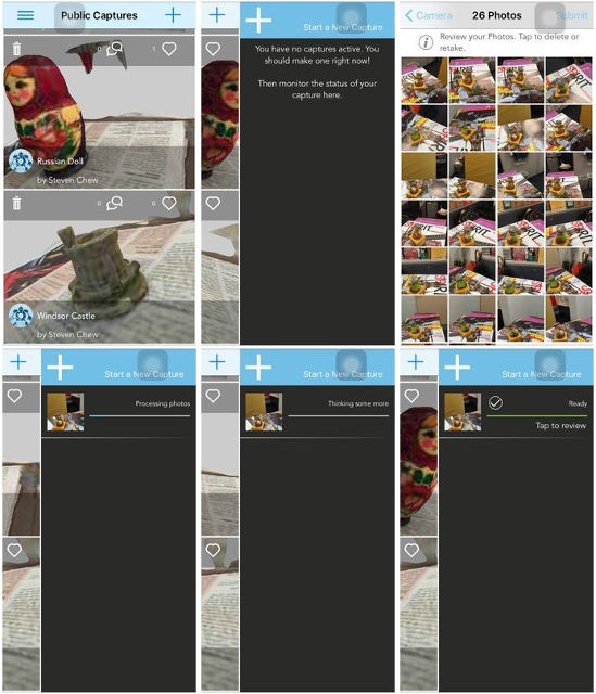
I have the software installed on my Apple iPhone, as I find it more convenient to take the photos I need using my iPhone's built in camera. The other bigger benefit of using the smartphone version of the software is that the app is able to guide the user during the photo taking process to improve the chances of a successful 3D scan.
The basic workflow for 123D Catch is as follows:
- Step 1: Log in to your 123D Catch account
- Step 2: Press + to start a new capture
- Step 3: Capture the photos following the onscreen guides
- Step 4: Upload to 123D Catch server & wait for processing to be completed
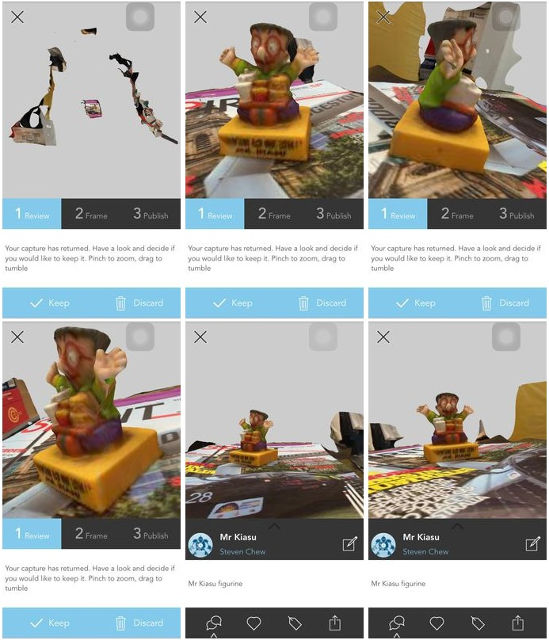
- Step 5: Review captured 3D model & click Keep to continue
- Step 6: Frame the captured 3D model & click Next to continue
- Step 7: Publish the 3D model
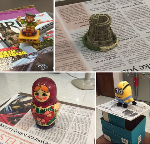
Capturing the photos to upload to the 123D Catch server can be done anywhere. All you need is somewhere with uniform lighting and space to move around the model. The pictures below shows the setup that I used at home and in my office to capture some of the models that I have uploaded to my Public Capture.
As you've probably noticed, the 3D model processed by 123D Catch has a lot of additional background objects which need to be removed. I first logged in to my 123D account and downloaded the images from 123D Catch.
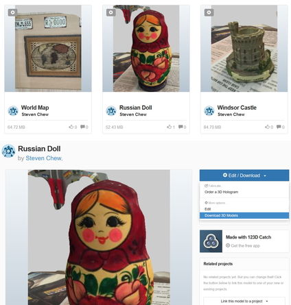
You have 3 options for downloading 123D Catch models - STL file, mesh package or photo package. To clean up the 3D model, downloading the mesh package would be sufficient.
Once you have downloaded the mesh package to your local computer, unzip it to its own folder. At this point, you need one of the mesh editors that I listed earlier: Meshmixer, Meshlab or Blender. I've decided to use Meshmixer to clean up my 3D models.
Once Meshmixer has started up, select Import>Import and navigate to the folder where you unzipped the 3D model. Click on the mesh folder and select mesh.obj. This imports the 3D model into Meshmixer for editing. In Meshmixer, clicking the left mouse button is the select button, clicking the right mouse button rotates the object and clicking scrollwheel and dragging the mouse pans the object. The scrollwheel allows you to zoom in and out of the workspace.
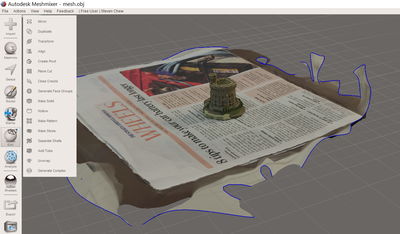
The first thing step in cleaning up my imported 3D model is to get rid of the unwanted background. To do this, I clicked the Select button on the left toolbar. This allows me to select parts of the meshes that I want to delete. Selection can be by painting the unwanted areas or by using a lasso tool. Once the unwanted portions of the model has been selected, pressing the Del key deletes the mesh. Pressing Ctrl-Z or Undo allows you to recover from any errors if you accidentally deleted a part of the object that you want to keep. Ctrl-Y is the redo command.
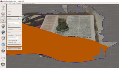
As you clean up your 3D model, it is important to use a combination of the scrollwheel and the right-mouse button to rotate and zoom in/out to ensure that you are editing the meshes correctly. The size of the brush tool can be adjusted as necessary. It is very easy to leave unwanted background that located some distance away from your model.
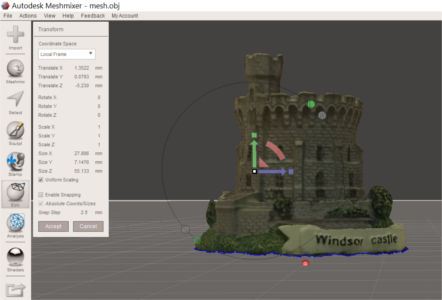
Once the model has been cleaned up, select Edit>Transform to move the 3D model over the origin, represented by a small red sphere on the workplane. Click the left mouse button over the direction arrows to move or rotate the model in the desired direction.
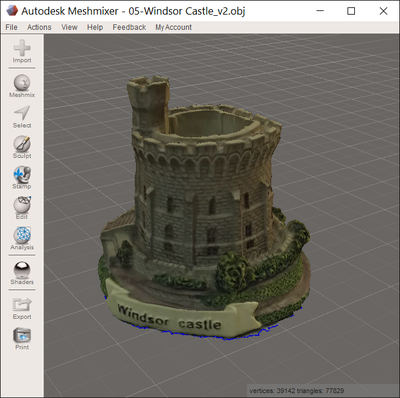
Once the above steps have been completed, we need to check the 3D model for any open manifolds and perform repairs to the meshes if necessary. This is done by selecting Analysis>Inspector from the toolbar on the left. Any holes that are discovered at this point is filled in using either a flat, minimal or smooth fill. Click on Auto Repair All to perform the repair, followed by Done.
The completed 3D model can be exported in various formats (obj, stl, vrml, svg, etc. using the File>Export option and sent to a 3D printer to get a physical replica of the scanned object.
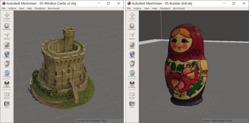
My completed & touched-up 3D scan model is displayed below. You can view more of my scanned 3D models by following the links after this section.
To view my scanned 3D models, click on the links below:
To download my scanned 3D models:
3D Scanning - Next Engine
We have a Next Engine in our fablab. However, it has not been setup yet. Once that is done, I hope to test it out, as the system is supposed to be able to produce 3D scans with 100 micron resolution and is used in organizations like the British Museum to digitize some of their displays.