This week the assignment is to make something big with computer controlled machining. In FabLab@SP, we have a large format CNC router the SK2030. The medium of choice is a 4’ x 8’ AA grade plywood. First and foremost, I want to thank one of my coursemates Tham for his experience in operating with the SK2030 CNC router. And not forgetting one of my coursemates Hendra introducing us to dxf2gcode and his best practices to use gcode.
trivia
This week is rather hectic for me. I am juggling between a 4 days in-situ course, moving to a cheaper accomodation, and trying to complete this week’s assignment. Grace under pressure.
Design methodology
Last week, I attended a 2 days workshop targeted at educators. In one of the discussion forum, there were a few mention of students with special needs, such as students with ADHD or hyper-activity. Currently, the devices made for such students are too unique in a classroom setting, and might run into the touchy issue of stigmatizing students with ADHD.
My design of the challenge chair is targeted to reduce such stigma in a class room setting. All students to be issued with the same furniture, but with the use of common class room equipment such as a basketball to disguise it the furniture for the need of ADHD student. The said challenge chair has a turn table as the sitting surface, this serves as rotation on the z axis. As for movement of the x and y axis, the said challenge chair will be prodded on a basket ball. This piece of chair is a challenge to sit on, for a regular person per se; there is not a fixed stable point while sitting on it.
May be it is fated for me to make this challenge chair. I have designed the prototype without a basketball, taking the necessary measurements from the internet, and hoping some kind soul would lend me one. With a stroke of luck, I chanced upon a discarded basketball when moving house earlier this week.
Workflows
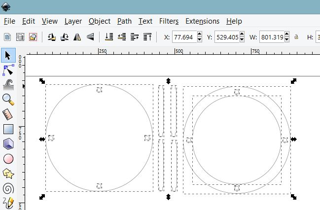
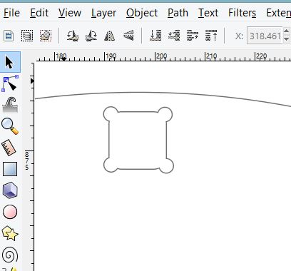
I designed the necessary parts to construct the design mentioned above in inkscape. . The design consist of 2 parts, a flat top where the turn table will be placed, and a hollowed out body to contain the basketball. I designed with the largest basket ball in mind, which is 250mm in diameter, and added 40mm to the radius for the ball to move freely. The joints is a simple slot in joint, the hole is designed using the dogbone shape as per depict in the following screenshot. My coursemates have reported the perfect size for a good it for slots to be 11.5mm. I have designed my challenge chair using the parameters reported. . From inkscape, one can export the file into standard such as dxf. My design in svg can be downloaded from here My design dxf can be downloaded from here
Unfortunately, our CNC router does not eat DXF directly, and it prefers to eat not GCODE *.nc but rather *.jg. One way is to use the provided software which is MASTERCAM to generate the necessary gcode, the gcode is then converted to *.jg. Alternatively, One of my coursemates Hendra introduced us to dxf2gcode
this allows converstion of dxf to gcode *.nc. Several modifications are needed to be done on the generated *.nc. Check out the writeup at below section. The *.nc is then coverted to *.jg with the JG Software.
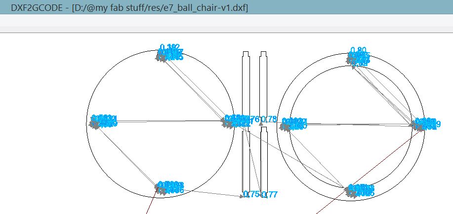
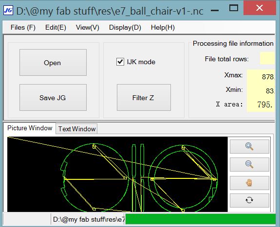
The following diagram describes the toolpath generated by dxf2gcode the generated gcode can be downloaded from here
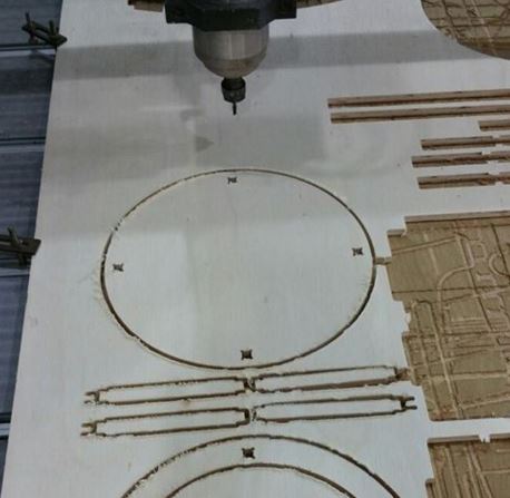
This gcode is then modified to jg that is then fed to our CNC router. The following picture describes the end process, after milling is completed.
update: workflow with DXF2GCODE gcode and jg
minor editing of gcode is required on the
config.cfg. The following parameters were recommended
from our experienced staff. A new tool parameter is
added, with diameter = 2.0, speed = 6000.0,
start_radius=1.0.
the gcode *.nc generated with DXF2GCODE can be
viewed in any text viewer.
one peculiarity in the generated *.nc, there will
be white spaces in between the x, y, z axis, and also
th i, j. For example, The following generated code "Z
15.0" white spaces to be removed to become "Z15.0";
rinse and repeat for all remaining white spaces.
Tabs are added manually in the *.nc. Tabs prevent milling bit from breaking while contouring, and also to hold the CNC routered parts in place w.r.t stock.
pluginging feed rate are set to F150.0 when Z3.0 and also F400.0 when Z-1.5. Ensure the milling bit is retracted to Z positive value at the end of CNC routing.
this *.nc is then fed to the JG software to be transformed into *.jg to be eaten by our CNC router.
update: workflow with mastercam and jg
Generally speaking, the workflow to work with mastercam can be described as follow.
first get the DXF format from the SVG file.
next place the DXF file into the Mastercam software, put in the necessary tabs, then generate the feed, speed, depth and passes, and finally generate g-code in *.nc format.
Our CNC router only eats *.jg, the *.nc file have to be converted by jgsoft.
The software workflow is described below.
First, From MasterCam open the design file.
Contours in the design file will break the milling bit easily. To
prevent this breaking of mill bits, square tabs are added to contours.
The mill machine type is selected
prepare the tool path by chaining the mill.
Important to check the following parameters such as clearance, retract, feed plane, top of stock, depth, on your CNC router before operation. In our CNC router the following parameters are set in absolute. Clearance = 50.0, Retract = 25.0, Feed plane = 10.0, Top of stock = 0.0, Depth = -11.5.
The GCode is then generated with Mastercam code expert. The *.nc file is then saved.
Our CNC router only eats *.jg, the *.nc file have to be converted by jg software.
using CNC-Change software
The following screenshot describes the CNC-Change software used to convert *.nc to *.jg
CNC router workflow
A piece of plywood stock is secured on the CNC router bed. The milling bit is zero-ed to the space to be CNC routed. The choice of milling bit is a 2 flute 6mm carbide milling bit. The following SK2030 machine dependent parameters are retrieved from our experienced staff: cutting speed at 21000 rpm, feedrate at 50% cutting speed and 10% plunge rate of the cutting speed. The *.jg in a usb flash drive is then plug into the controller. Use the onscreen menu to navigate to the required *.jg, then CNC route away.
Assembly and test
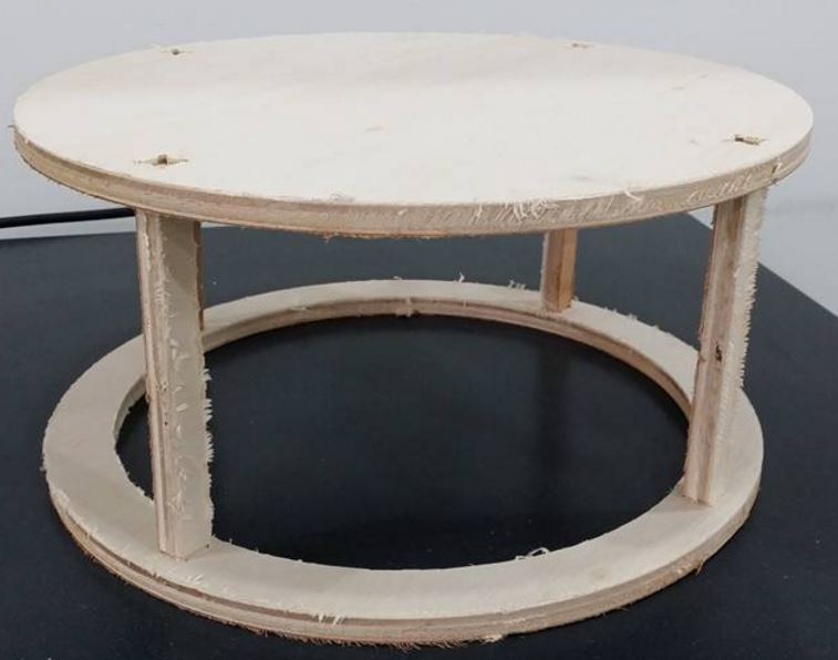
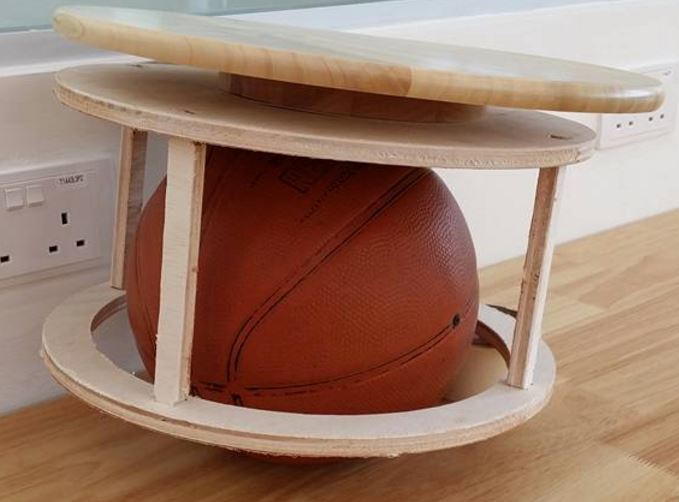
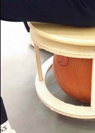
The following picture describes the pieces assembled. No glue or nails needed. The joints fit like a glove. this is the regular mode for normal person. The following picture describes the challenge chair mode, where the CNC machined piece is prodded on a basket ball, and install with a turntable on the seating surface. For the interest of time and upon recommendation of local instructor, I have used a lazy-susan that is lying idle in my office to substitute the turntable. One of my students came across my challenge chair in the fablab, and wanted to try it. The following picture describes the testing by my student. his comment: “very difficult to sit lahhhhh”
Source files Download
My design in svg can be downloaded from here
My design dxf can be downloaded from here
My design generated gcode with DXF2GCODE can be downloaded from here
My design generated jg can be downloaded from here
reference
DXF2GCODE https://sourceforge.net/projects/dxf2gcode/files/latest/download
milling formula http://www.esc-ltd.co.uk/Milling%20Formulas.pdf