Assignment 13
Задание 13
(2ND EVALUATION EDITION) In which I control LED stripe through transistor
В котором я реанимирую один из моих старых проектов
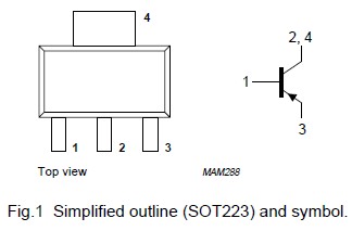
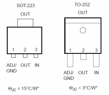
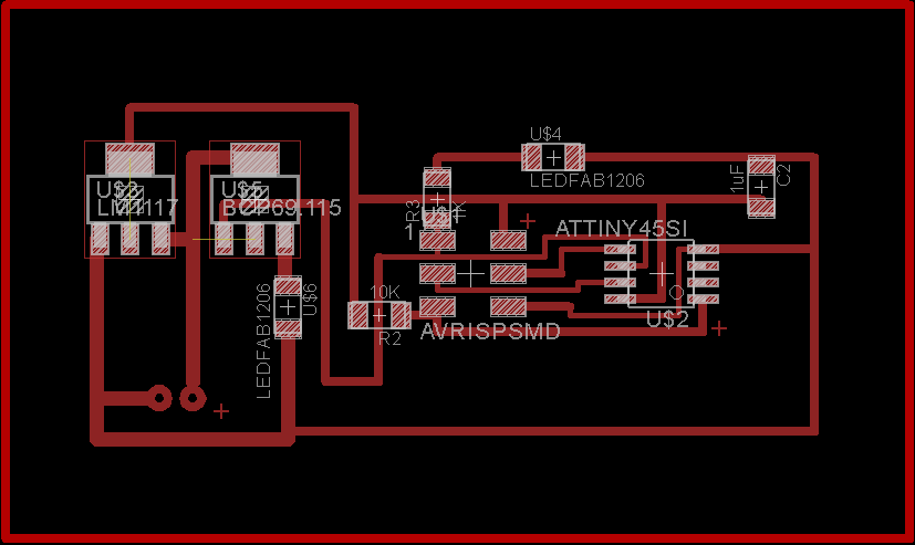
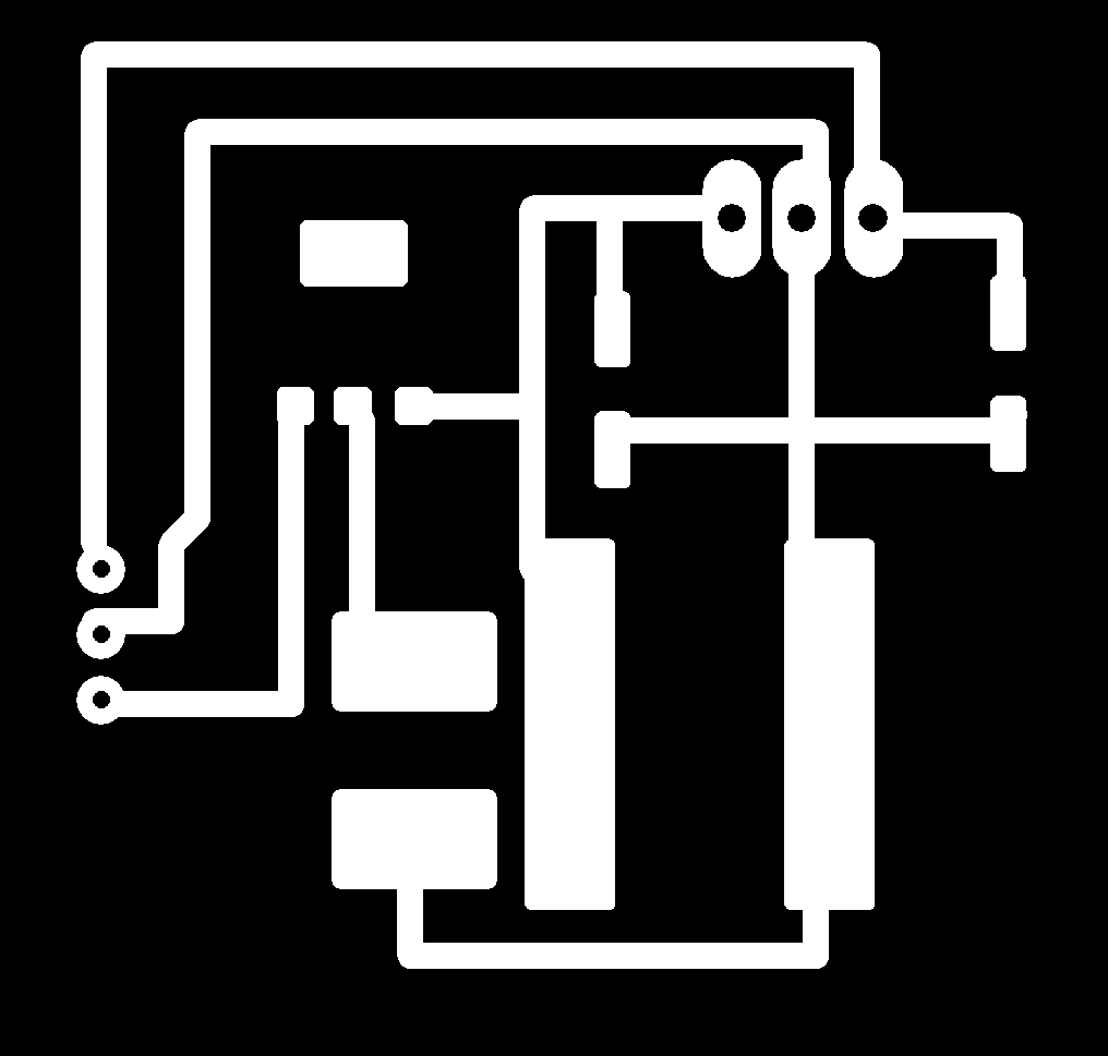
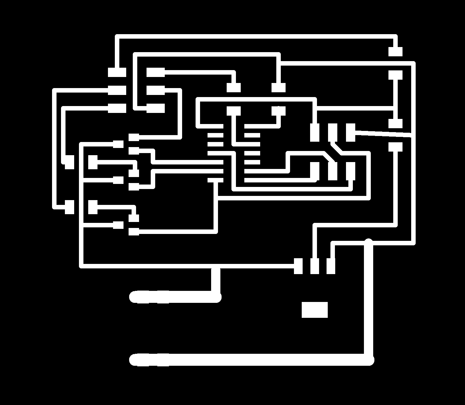
As I needed both 5 and 12 volts I had to convert 12V power supply to 5V and also make a 5V-controlled gate for 12V to control LED stripe. I chose LM1117 and BCP69 for those purposes and added the, to fab Eagle library
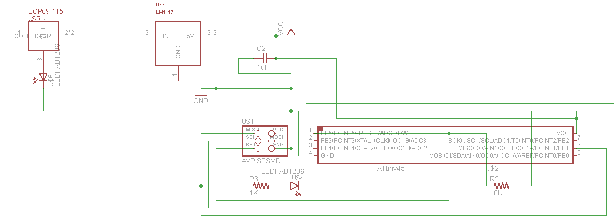
While making this pcb, I was refering to my previous pcb from input assignment both in schematics and layout
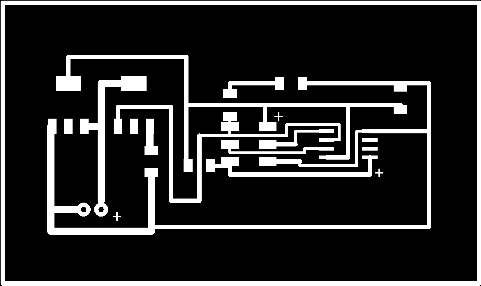
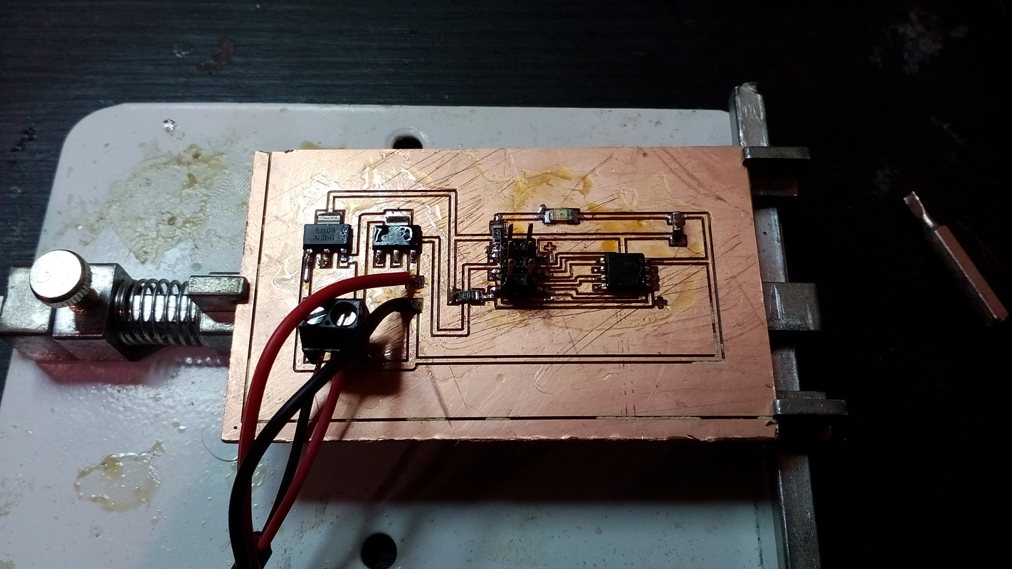
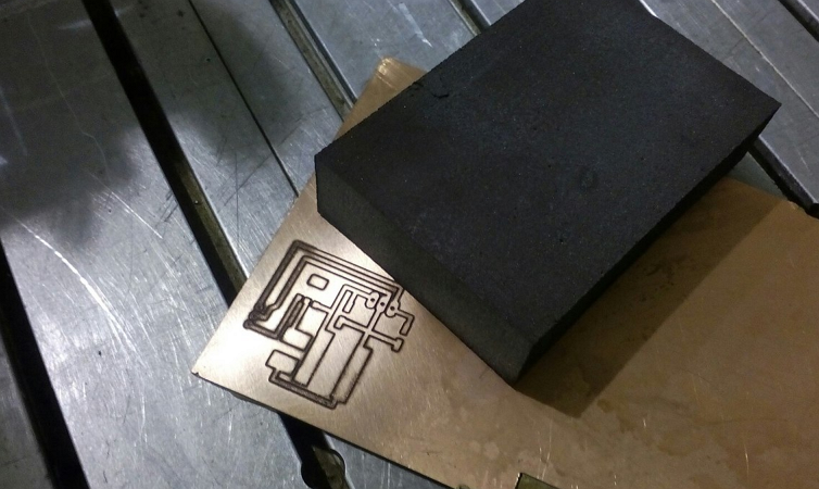
The board was milled as in electronic production assignment: I uploaded .png in fabmodules, calculated task as g-codes (PCB traces (0.010) ), converted g-codes from inches to mm and milled my pcb on K2 milling machine
  void setup() {
  pinMode(1, OUTPUT);
}

// the loop function runs over and over again forever
void loop() {
  digitalWrite(1, HIGH);   // turn the LED on (HIGH is the voltage level)
  delay(1000);                       // wait for a second
  digitalWrite(1, LOW);    // turn the LED off by making the voltage LOW
  delay(1000);                       // wait for a second
}
This is a simple blink sketch I used to test my pcb but this pin has PWM abilities so I also can use it as a dimmer
Transistor-controlled LED from Gleb Miroshnik on Vimeo.
LED controller test from Gleb Miroshnik on Vimeo.

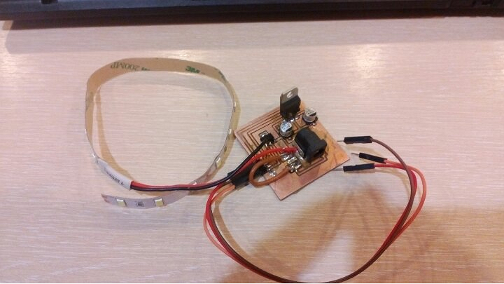
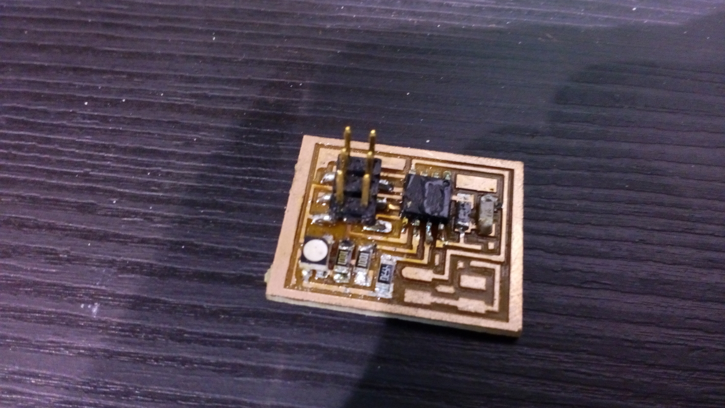
Next I decided to make a module to have an ability to remake only one part of the board in case of fail and also it makes board making more flexible: I can use this module for my pcbs and for Arduino projects
LED stripe module test from Gleb Miroshnik on Vimeo.
Final thoughts
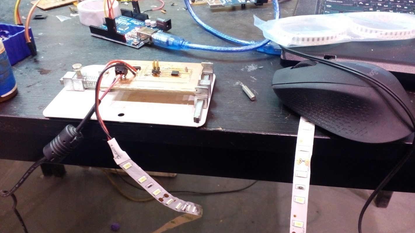
I don't know exactly why this test didn't work out with full-sized LED stripe but the controller was still alive and working after that test and it even controlled the transistor. My guess is very high current on LED stripe and power supply caused this lag. Hopefully, changing those components would help me overcome this problem in my final project. Also I managed to make this controller work as I changed connection of LED stripe. Now this module can be used with any pcb, all you need to have is the contacts: 5V, GND and signal to control transistor.
Downloads
Out.rar (includes Eagle files, traces in 600dpi .png; module Sprint Layout file and traces in 600dpi .png; and updated Eagle fab.lbr)In which I reanimate one of my old projects
В котором я реанимирую один из моих старых проектов
Previously, on Fab Lab Polytech... (THIS IS NOT MY ASSIGNMENT, IT'S AN INTRO ABOUT STUFF I MADE 2 YEARS AGO, MY ASSIGNMENT IS BELOW)
Ранее, в Фаблаб Политех
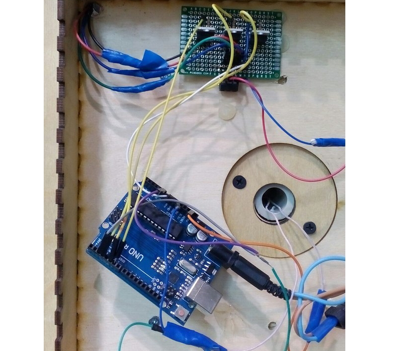
On VII School Fab Lab Polytech I was in charge of making one of the projects. The main idea was to create a current collector which could check which side of cube is faced towards viewer and set the appropriate LED stripe mode. I used three sets of diodes to make different cuttent values on input and three transistors to calibrate current on each channel of LED stripe. As you can see on pictures below project was realized with using arduino Uno (which is an overkill), mockup board with three transistiors and lots of insulating tape. Such a shame, really (but I was mostly concerned about mechanics that time). I'd redesign the board using ATtiny44, add a socket for 12V power supply and voltage transformer to supply mictocontroller.
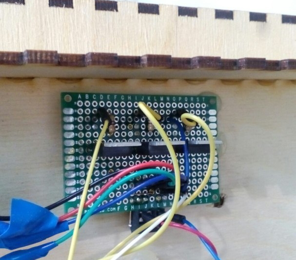
Milling - 3, Gleb - 0 (I failed two boards straight and broke a milling bit)

Left one has different depth of cut (my fault with fixing textolite)
Right one has no microcontroller soldering places (I guess, I tore them away when I was trying to clean a pcb with a steel ruler)

Gleb strikes back! (kinda)
Somebody might say that I gave up on that project but I prefer saying that I'm just preparing for something great. Making a whole fab led controller would be a great archievement but it'll take a lot of precious time which I don't have. So, I took Neil's rgb led controller and made it work.
void setup() {
  pinMode(0, OUTPUT);
    pinMode(1, OUTPUT);
      pinMode(2, OUTPUT);
}

void red ()
{
    digitalWrite(0, HIGH);
    digitalWrite(1, LOW);
    digitalWrite(2, HIGH);
}
void green ()
{
    digitalWrite(2, HIGH);
    digitalWrite(1, HIGH);
        digitalWrite(0, LOW);
}
void blue ()
{
    digitalWrite(0, HIGH);
        digitalWrite(1, HIGH);
    digitalWrite(2, LOW);
}
void cyan ()
{
    digitalWrite(0, LOW);
    digitalWrite(1, HIGH);
    digitalWrite(2, LOW);
}
void yellow ()
{
    digitalWrite(2, HIGH);
    digitalWrite(1, LOW);
        digitalWrite(0, LOW);
}
void magenta ()
{
    digitalWrite(0, HIGH);
        digitalWrite(1, LOW);
    digitalWrite(2, LOW);
}
void white ()
{
    digitalWrite(0, LOW);
        digitalWrite(1, LOW);
    digitalWrite(2, LOW);
}
void black ()
{
    digitalWrite(0, HIGH);
        digitalWrite(1, HIGH);
    digitalWrite(2, HIGH);
}
// the loop function runs over and over again forever
void loop() {
            // wait for a second
            red();
            delay(1000);
            green();
            delay(1000);
            blue();
            delay(1000);
            cyan();
            delay(1000);
            magenta();
            delay(1000);
            yellow();
            delay(1000);
            white();
            delay(1000);
            black();
            delay(1000);
}