
assignment 13
output devices
The aim for this week is design and code an existing input board and adding to it an output device.
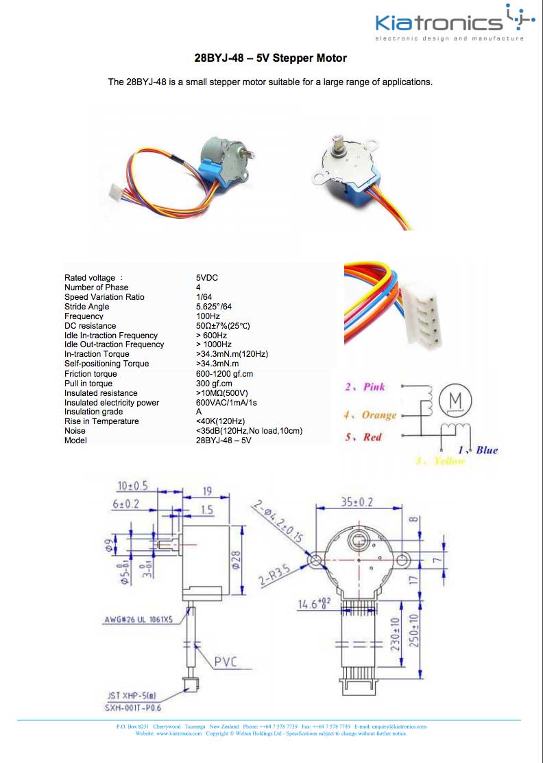
As for my final projects I want to use motors, I chose to add a motor to my potentiometer board and controll the speed. Bipolar Steppers are too big, So I wanted to try some unipolar steppers I had at home, they are way smaller. I have the 28BYJ-48 5 lead unipolar stepper. They work with 5V.
fabKit
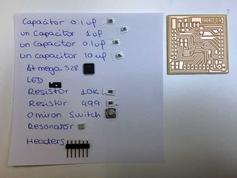
My first idea was to mill a fabKit board and design a board with the items I wanted to control, and take advantage of the fabKit and re-use it for other experiments.
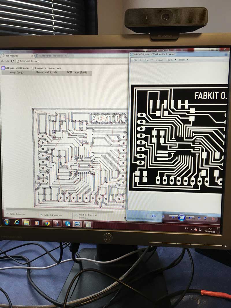
I downloaded the *.png files and started to mill the v.4 board. It looked nice!
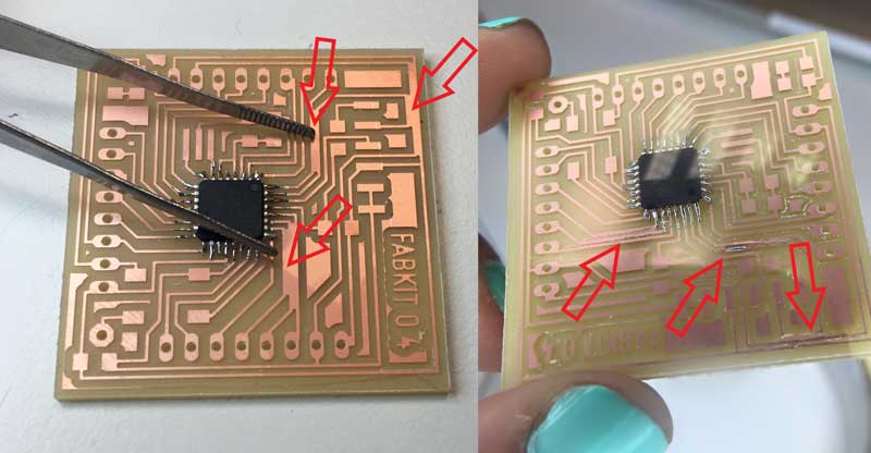
But then when I started soldering I figured it out that some traces were not milled, the board needed postproduction!!!
Testing with the multimeter, it seemed to be fixed.
Then, connecting the fabKit to the fabIsp to program it, I checked the connections wrong, following a previous version pinout scheme and burned the microcontroller :( (for sure, it was overheated and smelled very bad)

No surrender! I had the choice of milling a new board, but I saw on fabModules that the fabKit v4 was not doing the traces properly (as before). I figured it out that that version was designet to be milled with a laser cutter, so It needed more definition that the one I can get with the Modella. I asked my remote instructor and understood that I needed to mill the fabKit v.2.
But unfortunately I broke the milling head a little while after It started milling. Because we had some issues with them at the lab in past assignments, we only have two 1/64 milling heads left. My colleague Jose at that moment didn´t milled his board yet, So I had to stop my assignment to let him work.
2nd fabkit
My super-guru and remote instructor Nuria is super cool. This weekend was a long holiday in Spain, and riving back from Asturias, I stop by fabLab León and she gave me a milled and cutted fabKit and a motor driver for my stepper motor and Arduino.
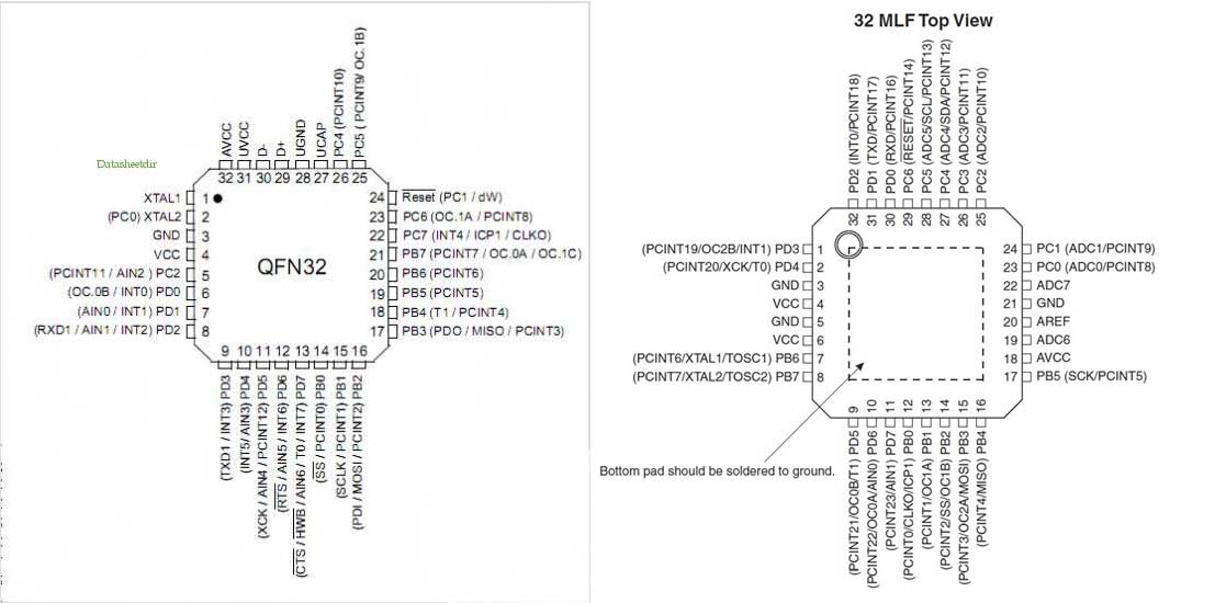
I was super happy with my new FabKit, but then checking the pinouts, I figured it out that I messed it up with the microcontroller, I took an Atmega 16U (LEFT), that has different pinouts that the 168/328 (RIGHT).
When I tried to change the microcontroller, because we don´t have heat gun at out lab, I totally messed It up and broke the traces. Super fail vol.2.

Because it seems that I have a hex with fabKits, I decided to design & mill a simple hello.stepper board with a potentiometer.
Hello stepper


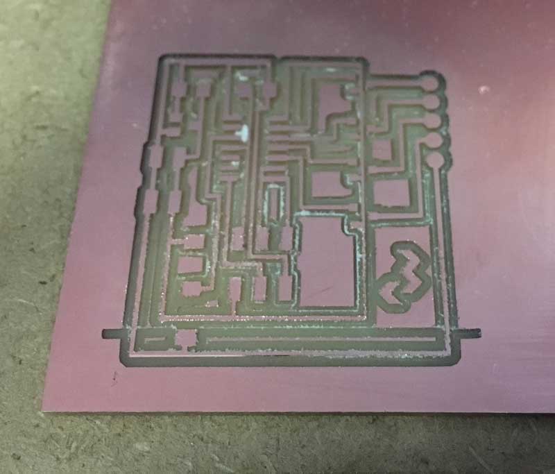
The board unglued from the sacrifitial layer when it was milling the outline, and it moved from its place, so I had to cut the board with a guillotine. It´s not a good tool, the board gets cracked.
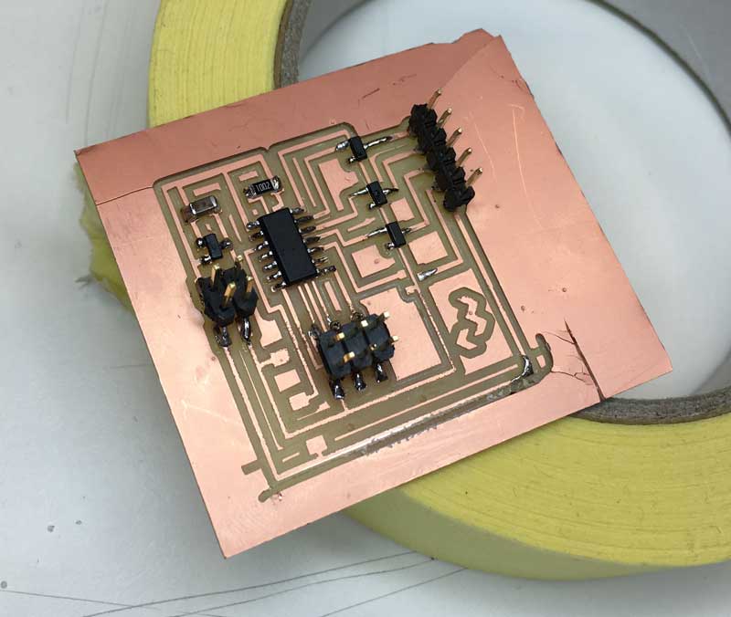
I forgot the potentiometer at home, but I least I could burn the bootloader and check if the board its ok. but it seems not. I double-checked the soldering and connections and it looks ok. But Arduino keeps telling me that It can´t burn the bootloader.
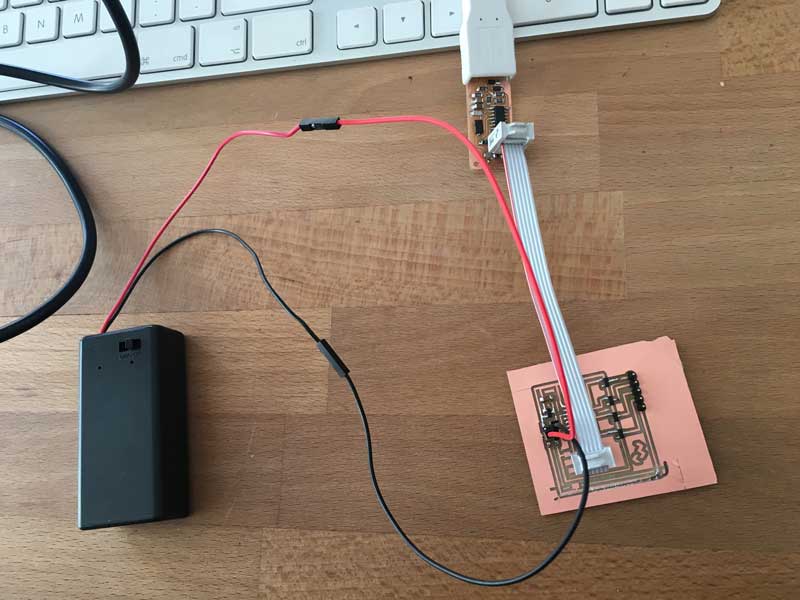
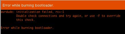
I will ask for help, I think that my schematic is ok, but maybe the issue comes from the design, not from the soldering.
Arduino Testing
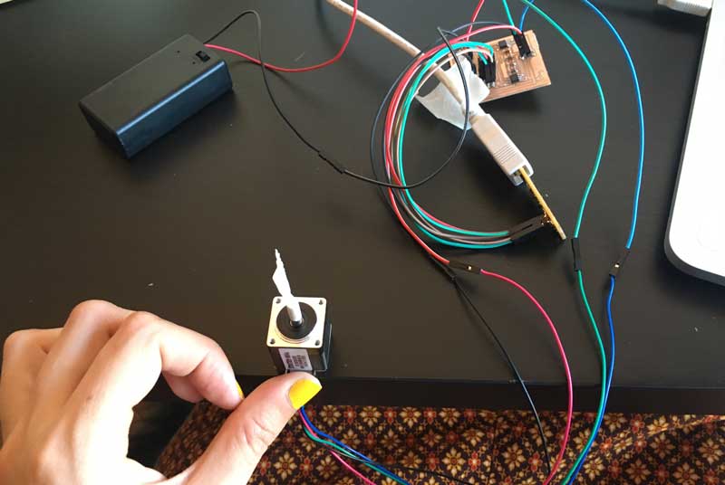
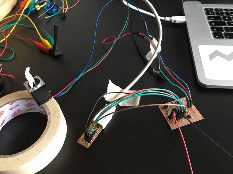
As it seems I can´t move the motor with my hello.stepper board, I made a test with Arduino.
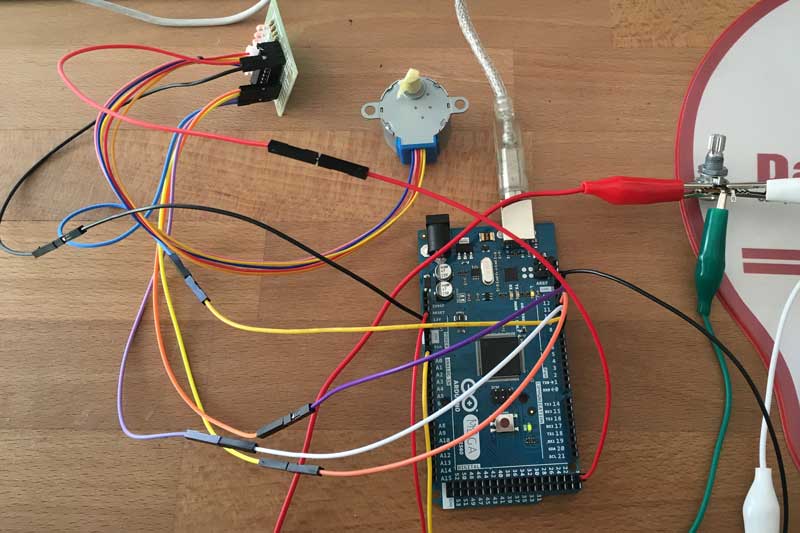
I used an Arduino Mega, a 10k potentiometer, and a ULN2003 driver for the motor.

I used the AccelStepper library because i worked with it more times. I adjusted the potentiometer value to speed.


The motor has not the speed range I thought it had...I think I must rethink the final project, or at least, the way the discs or items should move.
Quite a week.
Changes
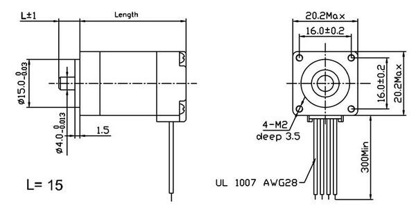
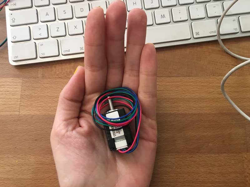
As I see that the unipolar motors doesn´t fit to my purposes, I decided to test with bipolar motors. I worked with the classic Nema17 in the past, but they are too big. I searched for the smaller ones of the Nema Family. I found the Nema8.
I redesigned the hello.stepper.bipolar board from Neil and added connections for the potentiometers, but I couldn´t mill the board yet.
For test the motor, I made some testings with a Ramps 1.4 shield that I had at home, with an Arduino Mega. This shield has 5 polulu motor drivers. It´s suitable to build 3d Printers. I used a 12V switching power supply and a 10K potentiometer.
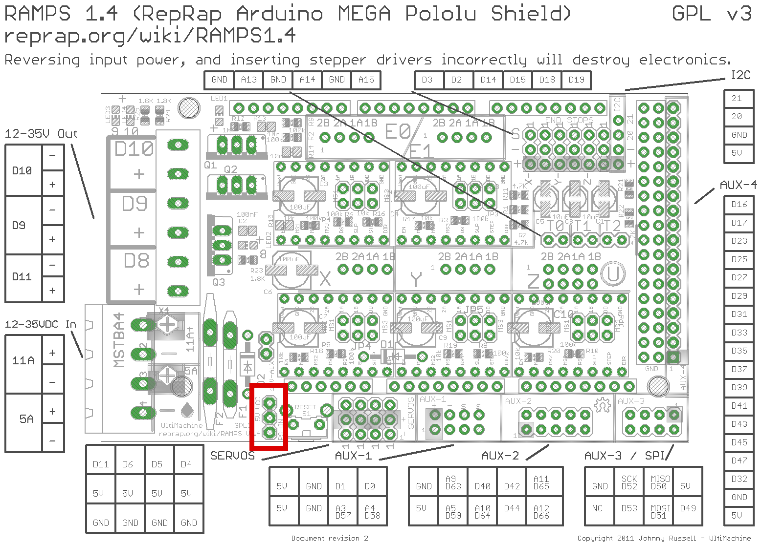
The shield schematic pinout is very useful to find the analog and digital pins correspondances.
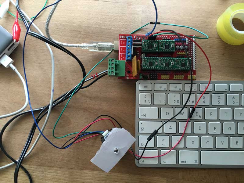
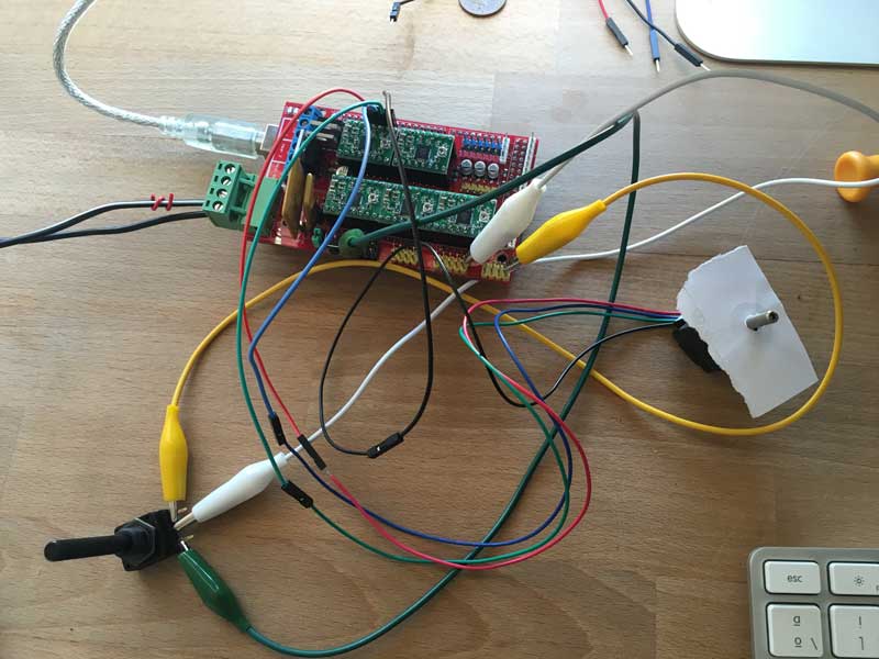
It´s giving better results than the unipolar one, and the size difference is not that big. I´m using the Accelstepper library.
Hello bipolar
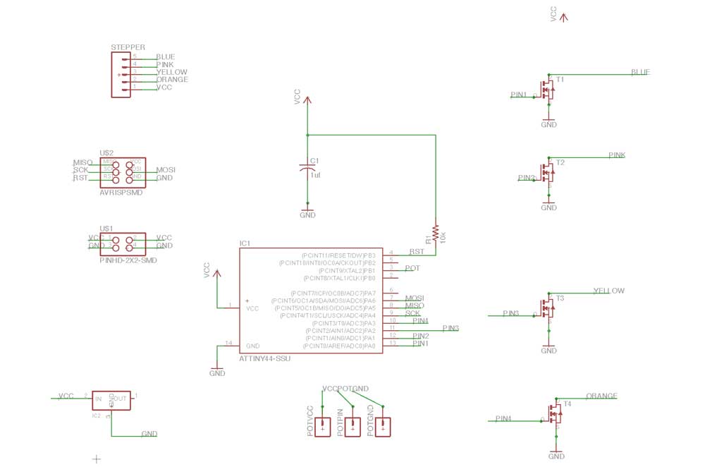
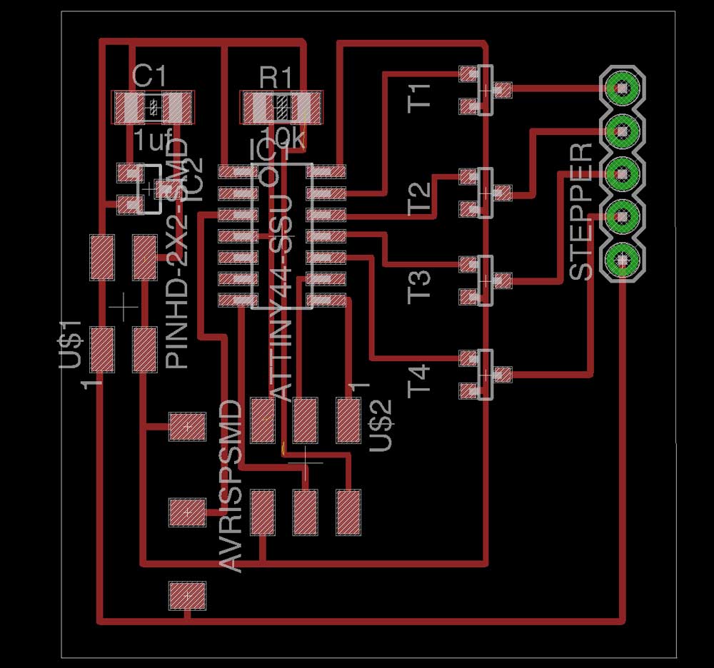
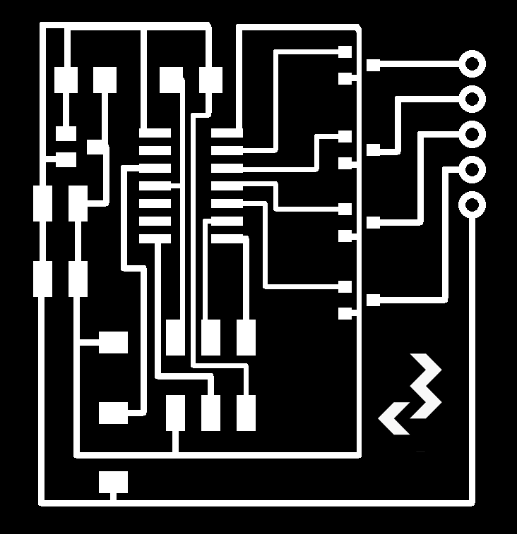
Ok, lets design in Eagle a new Hello Bipolar board. I´m updating this assignment with the board designed for networking & applications week. (with free pins for BUS communication). I used the attiny´s 44 datasheet for check the available analog to digital pins, I needed one for the potentiometer and 4 for the H-bridges (2 by stepper coil).

Postproduction! Overlaped traces. GND and VCC were joined and the regulator was overheating.


I fixed the overlaped trace:


I tested it with a basic Arduino example from Stepper library. At the beggining, the motor moved properly, but in a while I realized that it was trying to move with no success. I was powering the board with a 9V battery. I talked with colleagues from my supernode that made bipolar boards, and they were feeding it with 12V. It seemed to move in a better way, but one of the H-Bridges was overheating.
Failing bipolar from Marta Verde on Vimeo.
Nema 8 from Marta Verde on Vimeo.
OUTPUT DEVICES |
|
Described your design and fabrication process using words/images/screenshots |
X |
Explained the programming process/es you used and how the microcontroller datasheet helped you |
X |
Outlined problems and how you fixed them |
X |
Included original design files and code |
X |