This week we looked at computer-controlled cutting. This evolved from from our look at CAD the previous week. Our assignment is to design, create, and manufacture a GIK or press fit construction kit. This is to be done using the main tool we discussed in our global lecture, the laser engraver/cutter. We were also asked to demonstrate using a vinyl cutter, the other tool we looked at. This was very exciting as we finally get to use the tools to take our CAD designs and make physical objects from our creations.
This week uses what we learned last week with computer-aided design, to make sure we incorporate parametric design into our files. Last week I started to use SolidWorks and I will revisit using the software again this week to create the files. Neil also suggested using the clone feature in Inkscape and I will try that as well. InkScape is intuitive to use and the clone feature works really well for a basic parametric design. I also used SolidWorks and had some help from another Fab Academy member, Karen, to help me understand how parametric linking works within SolidWorks. I learned how to link items in SolidWorks and better my comprehension of how the software works.
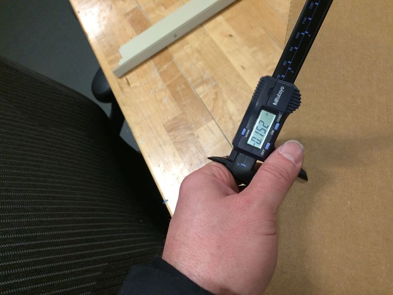
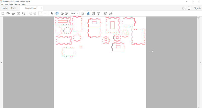
I started the process using Inkscape as Neil had suggested to try the cloning feature of the program. I decided to create several shapes to make boxes in my design. The boxes were to be able to connect to form square and rectangular boxes. I laid out my shapes on Inkscape using the rectangle shape and then cloned smaller rectangles to be the tabs on the boxes. I used the Union and Difference tool under Path to create tabs that would line up correctly when I laser cut them out. I spent alot of time working through the process and headed back to the Fab Lab ready to cut out the boxes so they would be press fit. I had measured the cardboard with calipers before I left on Wednesday to make sure I thought I knew the correct size thickness.
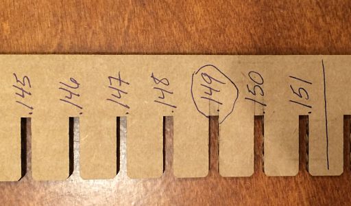
Caliper Reading | Inkscape Drawing
I then imported the file into Corel Draw using a .pdf of the file. I made sure it was in hairline and sent it to the Epilog Helix laser to cut out the parts. After I took the parts out of the laser and immediately started to put them together to see if the press fit would work. I found they did go together, but they would not stay in a press fit position. I forgot to include the thickness of the cardboard into the equation and the sides fell off. I knew I had to go back to the drawing board to finish up the project. This meant going with my earlier plan of using SolidWorks to create joints to slide the pieces together with.
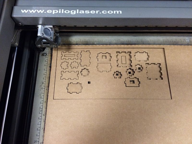
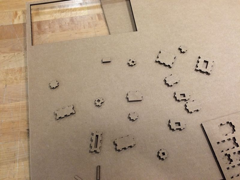
Laser Cutting Design | Failed Assembly
I knew I had to quickly change direction with my design. I had started a design in SolidWorks on Wednesday before I left the lab and had several hours to complete the assignment before I had to return home. I decided to open up SolidWorks and continue with my design of the press fit parts. I decided to scrap my initial Inkscape project because I did not think the joints on the box would hold like I would need them to with the design. I figured that instead of a open sided notch, I would use a slotted part with fillets on the opening and created several shapes. I decided to create 4 different pieces using the same formula to create the parts. I created parametric linking from the slot I created so when altered the distance of one notch, it would adjust the size on all the notches I created. I was also posed with the dilemma of what size was the notch. I did not want to create a press fit kit several times so I needed to create a template of notch size because you need to take into consideration the material that is removed in the laser cutting process and than can create a looser fit than is required by the project. The cardboard was cut to the right size and several different sizes were cut on the laser to determine the best fit. It appears that .149 is the best cut size. This is just smaller than the caliper reading of .152. It was worthwhile to check the diameter of the notch to get a correct and tight fit, without ripping or compressing the cardboard going into the slot.
I then started to create my parts using the correct dimensions and parametric design. I created the file in SolidWorks and made sure all my four parts were on the same planes and all linked together. As you can see from the photographs of the project, the files use linking to maintain the correct .149 diameter of the slot on each piece. I found SolidWorks to be much easier to create exact parts than in Inkscape for this application. I also could get more granual control of each piece using SolidWorks.
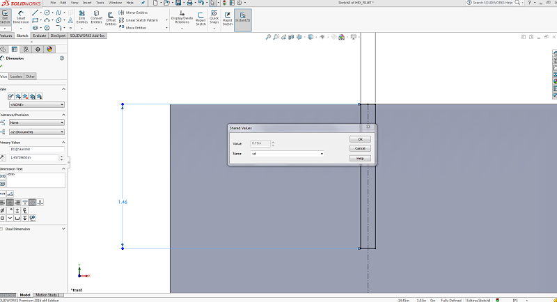
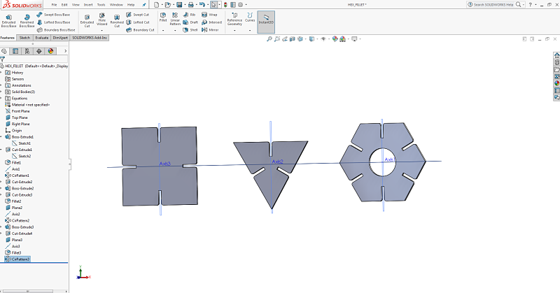
Parametric Linking | Three of My Shapes in Same Plane
I then needed to send my files to the laser cutter to produce. I first exported them as a .dwf file. I then printed them and found that they were still dimensional so I had some sides were smaller because it was cutting them on an angle which sheered off the sides. I was frustrated, but decided to export it from SolidWorks as a drawing file, which created a 2D model instead of the 3D that was pulling into Corel Draw. It was a small frustration but a good learning experience of how to export form SolidWorks to Corel Draw and then to the Epilog. As you can see in the photo beneath on the left, it cut too much on the right side of each piece because it was interpreting it as a 3D sketch instead of 2D.
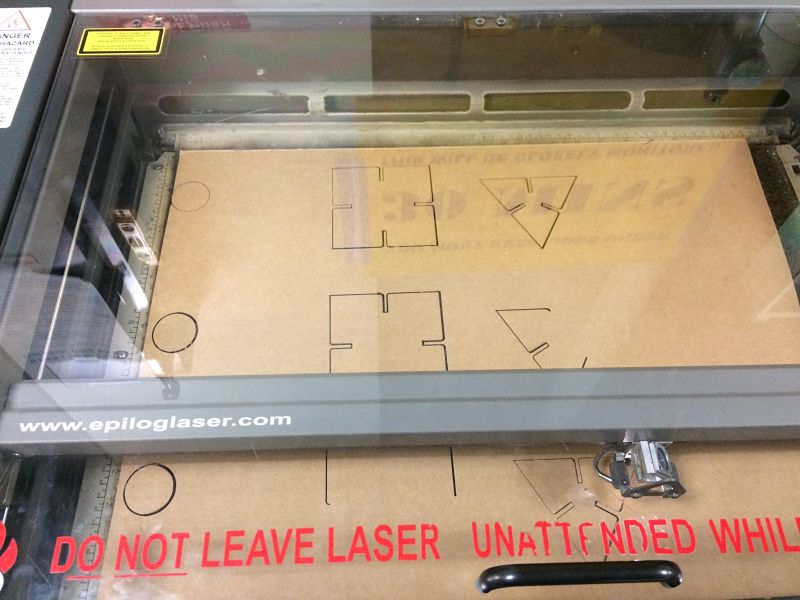
Notice Right Side Too Much Subtracted | First Batch Of Pieces Too Small On Right Side
I was able to then push my correct drawing files from SolidWorks to get the cut I needed on the laser. I imported the drawing into Corel Draw and then maximized my 24inch by 18 inch cutting area to create more pieces on the cardboard for one final cut to produce my press fit construction pieces.
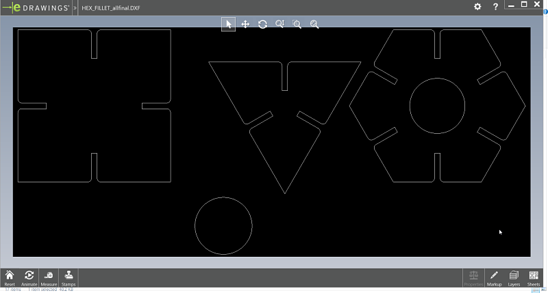
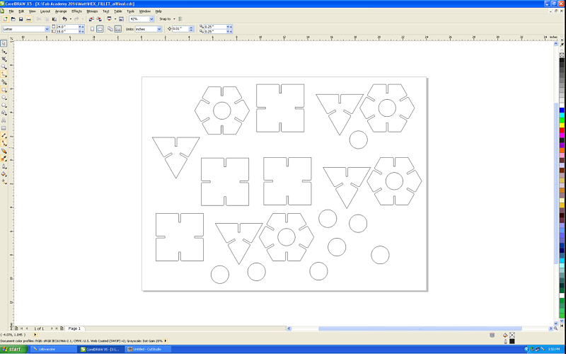
ePub Drawing File From SolidWorks | Imported Corel Draw File Ready To Print
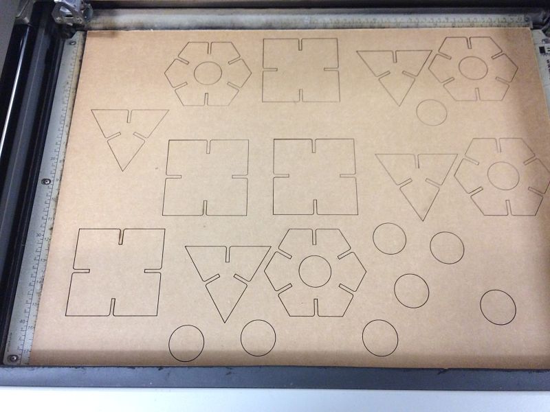
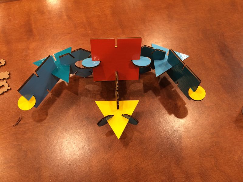
I then printed my pieces and they seemed to fit well. I was very relieved that I had been able to create my parts using SolidWorks, Corel Draw and the Epilog laser. It was all starting to come together using parametric design and CAD.
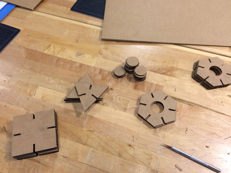
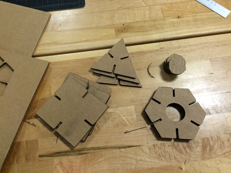
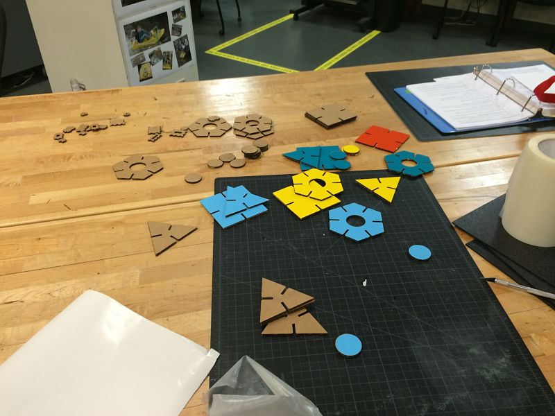
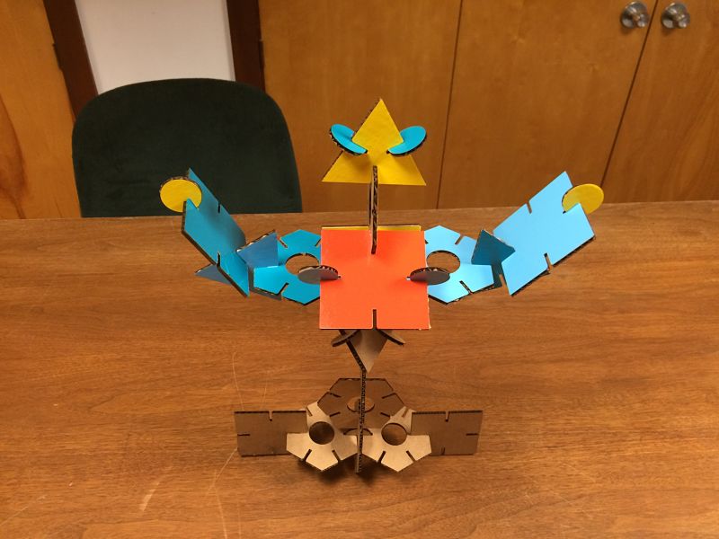
The Final Parts | Ready to Start With The Vinyl
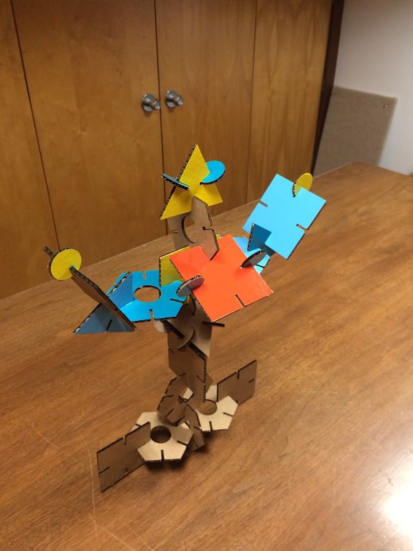
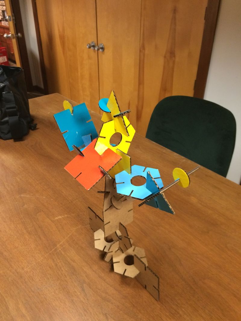
We were asked to demonstrate our use of the vinyl cutter. I decided to use the same file I had used in Corel Draw to then cut vinyl for my press fit construction pieces. I did not want to cut all of them but just a few to add color to my kit and not be so consumptive on the vinyl. I was able to print from Corel to the Roland vinyl cutter. I also learned how to cut just the first part of the roll when I load the vinyl into the machine by choosing to cut for the back. It saved a lot of material as the setttings had defaulted to cut roll from the middle and that wastes alot of vinyl. I went about the process of choosing several colors and made four cuts on the vinyl cutter. I then went about weeding the material, using transfer tape and then applying the material to the cardboard pieces. I found I could reuse the transfer tape multiple times to eliminate waste as well. As I finished up it provided much needed color to the press fit set.
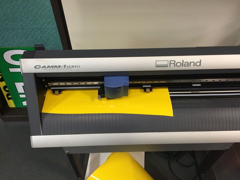
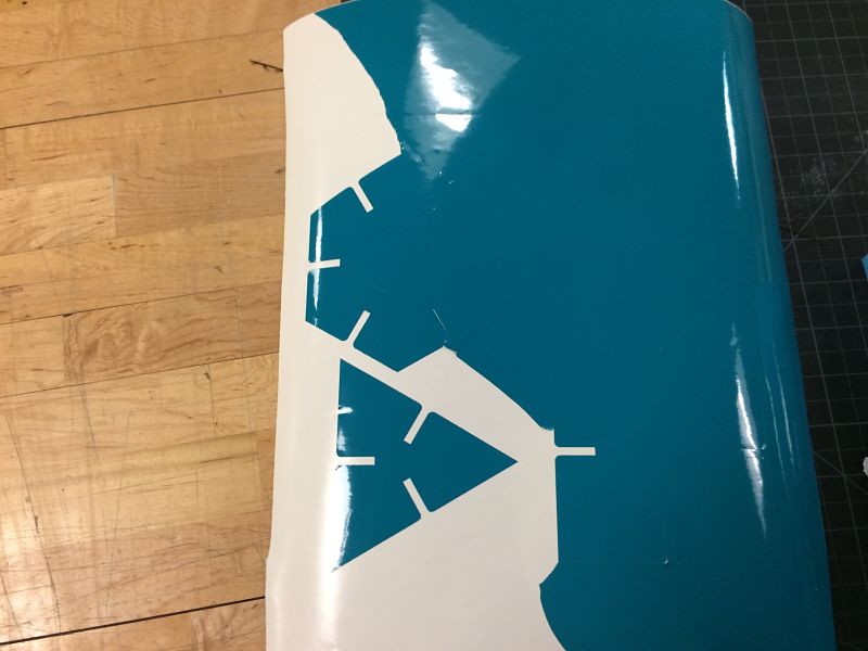
The Roland Vinyl Cutter | Weeding The Vinyl
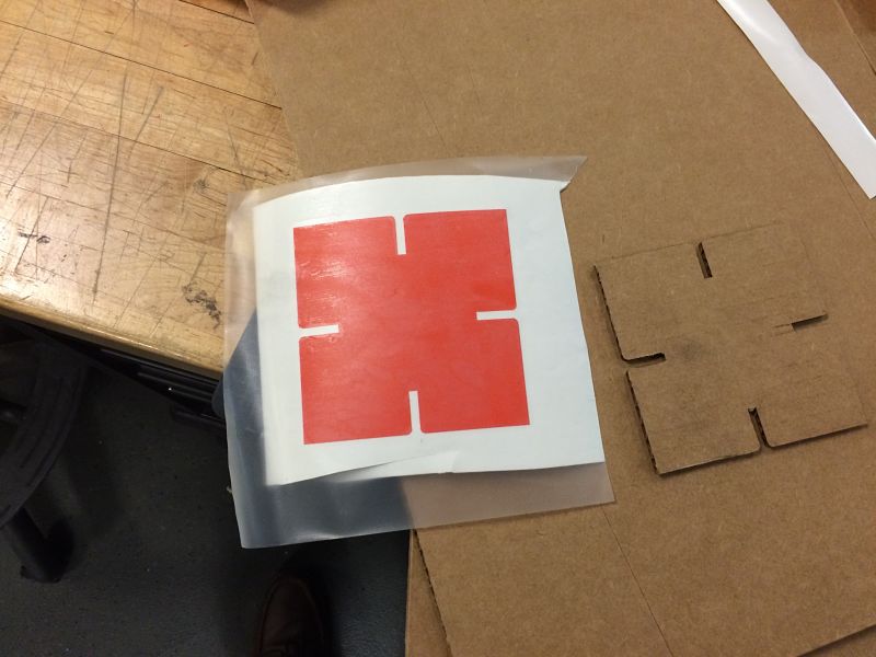
Transfer Tape | Pieces Covered With Vinyl
This week focused on design thinking with Bruce Mau of the Massive Change Network. Bruce provided strong evidence as to why design thinking is beneficial not only in the development of your ideas and products, but for financial success. He cited the 229% gains made by companies striving to really look at design thinking and design. I found his journey fascinating as he sold his Bruce Mau Design and started the Massive Change Network. His involvement in solving real problems, like Mecca, only solidifies my belief that schools at any level need to include students in solving real problems using design thinking as a component.
Project Files: