In the ninth and tenth weeks we are tasked with building a machine as a group. First we design and build our machine and test it manually to make sure that there is no binding of components. Next, we automate our machine using a PCB programmed for the motion we need. All of the designing, building, programming and testing will be performed by the team members.
Here is a list of the team members.
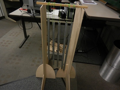
We discussed our machine design starting in the first weeks of the course. Many different ideas arose. Foam cutters, lathes, drawing machines and others. Eventually we settled on making a machine that played wind chimes. We would have a total of five chimes that would sound good when played together. They would be struck by some mechanism connected to an axis drive. The sound would be random as if thewind were mving the chimes against each other.
Working as a team we met and planned our solution. We needed some device to hold the wind chimes and the axis drive mechanism. We needed something to strike the chimes to make a sound. We also needed some method of control.
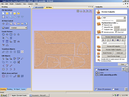
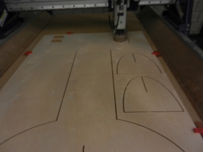
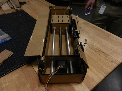
Individuals then started to work on separate tasks. Karen worked on creating drawings for the machine. Karen (the musically talented team member) would also cut and tune the chimes. I would take Karen's designs and using Aspire and the Shopbot cut the pieces for the framework. Chris worked on the Gestalt boards and the programming. Matt made the cardboard boxes to hold the axis-drives and created the groups home page.
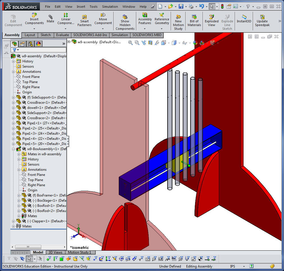
Karen sent me the design files to make the framework of our chime machine.
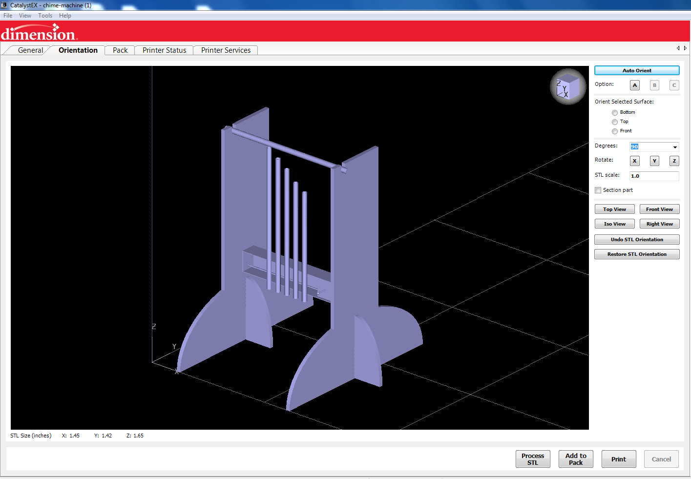
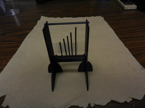
The first one is a rendering of what the machine will look like when finished.

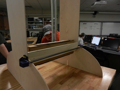
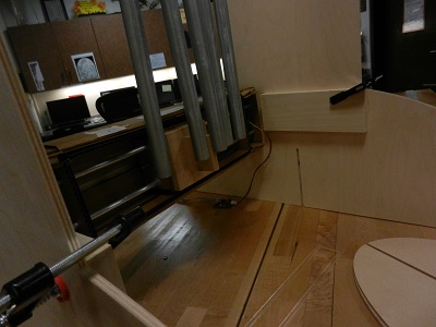
The first problem we encountered was an issue of speed. We discovered that when we attached the axis to the frame we bowed it enough to cause some friction. We loosened the screws slightly and that seemed to fix the problem.
The second problem we had was using a wood ball to strike the chimes. The pipes seemd to hang up behind the ball. I made a flat wood plate with a rounded edge and the action of the machine improved.
We discussed some of the ideas that would improve the design of the chime machine. Edit the cutfiles for the ULINE boxes, eliminate some of the folded pieces in the boxes (too thick), shore up the rigidity of the machine to see if it would improve sound and possibly make the box out of a material other than cardboard.