Arduino compatibles on a breadboard
My vision for this project stands and falls with the capability to read hex code, store it in memory and load the hex code on-the-fly onto another Arduino. It is the core of what I want for the Arduino-based gaming console.
I have already begun to investigate to what extent it is possible to read a piece of hex code in memory and burn it into another Arduino's Flash ROM. I successfully did that with a small code fragment, the Blink example from the Arduino IDE. I was using two Arduino Unos and noticed that the memory was exhausted pretty soon. I investigated further and stripped a Breakout game I am developing down to its bare essentials, but even this did not fit into the small memory footprint of the Arduino Uno. It is worth mentioning that the hex file for the game code must fit into the Arduino's memory completely.
As I want to program nifty videogames with multiple stages, collision detection, a frame buffer, and melodies, I need much more memory than what the Arduino Uno has on offer. I would like to use an Atmel ATmega1284p which has four times the memory of the Arduino Uno and is not too hard to solder. As this chip is not used by any device in the Arduino family, I need to check first whether I can implant the chip into the Arduino ecosystem. This is the more important, as I want to use the Arduino IDE for software development.
June 24th.: Why Arduino IDE? My hope is to bring to live a small but thriving community of non-experts who eventually contribute games to the LEDmePlay or who build their own LEDmePlay consoles. So far, at least ten people have done that. With a simplified approach on programming, I want to lower the threshold for them.
Groundwork: Arduino Uno in a breadboard design
For training and to learn the basics, I will first build an Arduino Uno on a breadboard, burn the bootloader into its ATmega328P and let the Arduino Uno do something. After that I will repeat this for the Atmel ATmega1284P.
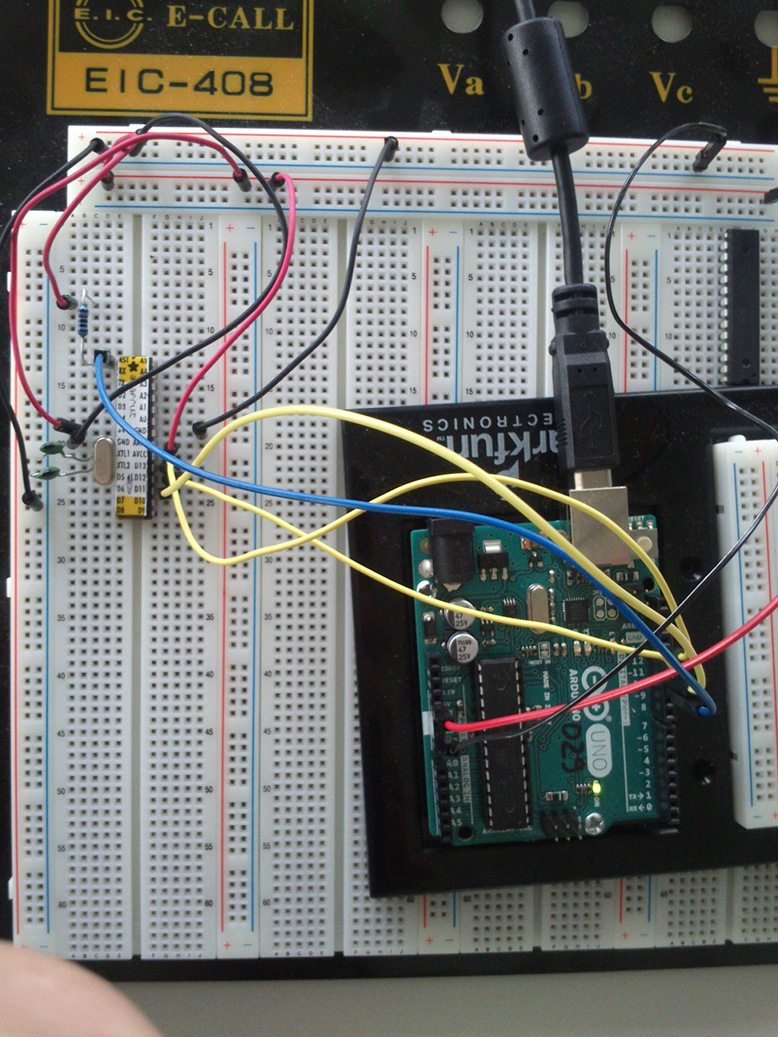
For the general design of the Arduino Uno on a breadboard, I followed a tutorial from the German Make magazine. I cloned their cabling between Arduino Uno and ATmega328P (not shown).
Burning the bootloader:
To install the bootloader onto the ATmega328P, it needs to be burnt into the Flash ROM. Atmel has designed the ISP interface for this very purpose that makes it possible to program a barebone ATmega processor via the Serial Peripheral Interface (SPI). As the serial RS232 interface transmits data asynchronously, it is incompatible with the synchronous SPI interface. An ISP programmer is needed, therefore, that translates the signals, or one can use an Arduino to do the task. In the Arduino IDE v1.6.9, I needed to load the ISP sketch from the examples, uncomment the line "#define USE_OLD_STYLE_WIRING" in order to make it work with digital pins 10 - 14 (see comments in the sketch itself), and then burn this into the Arduino Uno. The procedure is exactly the same as with "ordinary" sketches. It was successful.
When I wanted to burn the bootloader into the ATmega328P, I switched to programming mode "Arduino as ISP" and selected "Burn Bootloader" in the Arduino IDE's menu. A few seconds passed, then I got following error message from the Arduino IDE:
        1
        2
        3
        avrdude: Yikes!  Invalid device signature.
        Double check connections and try again, or use -F to override
        this check.
Why did this happen? I double-checked my cabling. It seemed correct and the same as in the tutorial. It turned out that the tutorial lied at me in the ISP programming section. A visitor who left a comment in the magazine's forum was also unable to burn the bootloader on his chip. He recommended the slightly modified cabling that is detailed in this article.
I wired up Arduino Uno and the ATmega328P on the breadboard as detailed below:
        Digital Pin 10, RESET (Arduino Uno)         --      Pin 1, RESET (ATMmega328P)
        Digital Pin 11, MOSI (Arduino Uno)          --      Pin D11 (ATmega328P)
        Digital Pin 12, MISO (Arduino Uno)          --      Pin D12 (ATmega328P)
        Digital Pin 13, SCK (Arduino Uno)           --      Pin D13 (ATmega328P)
        GND (Arduino Uno) -- film capacitor 22pF    --      16 MHz quarz, 1st leg -- Pin XTL1 (ATmega328P)
        GND (Arduino Uno) -- film capacitor 22pF    --      16 MHz quarz, 2nd leg -- Pin XTL2 (ATmega328P)
        5V (Arduino Uno)                            --      AVCC (ATmega328P)
        5V (Arduino Uno)                            --      +V (ATmega328P)
        GND (Arduino Uno)                           --      GND (ATmega328P)
        5V (Arduino Uno)                            --      5V (ATmega328P)
        10 kOhm resistor between 5V (Arduino Uno) and Pin 1, RESET (ATmega328P)
The correct cabling is shown in following image that was taken from here. Pin 7 is "+V". Suffice is to say that I could now burn the bootloader onto the ATmega328P as expected.

Turning the ATmega328P into an Arduino Uno:
Above procedure has set the ATmega328P's fuses in a way that it now expects an external 16 MHz quarz oscillator. I have already added the quarz and the necessary capacitors to the design on the breadboard.
If it seems adequate, I will continue in this section and turn the design into a full-blown Arduino. This is currently not necessary.
ATmega1284P in a breadboard design
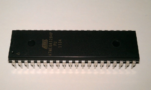
As the Atmel ATmega328p in the Arduino Uno, the Atmel ATmega1284P-PU is an 8 bit microcontroller chip in a DIP package. Below image which was taken from here shows what it looks like:
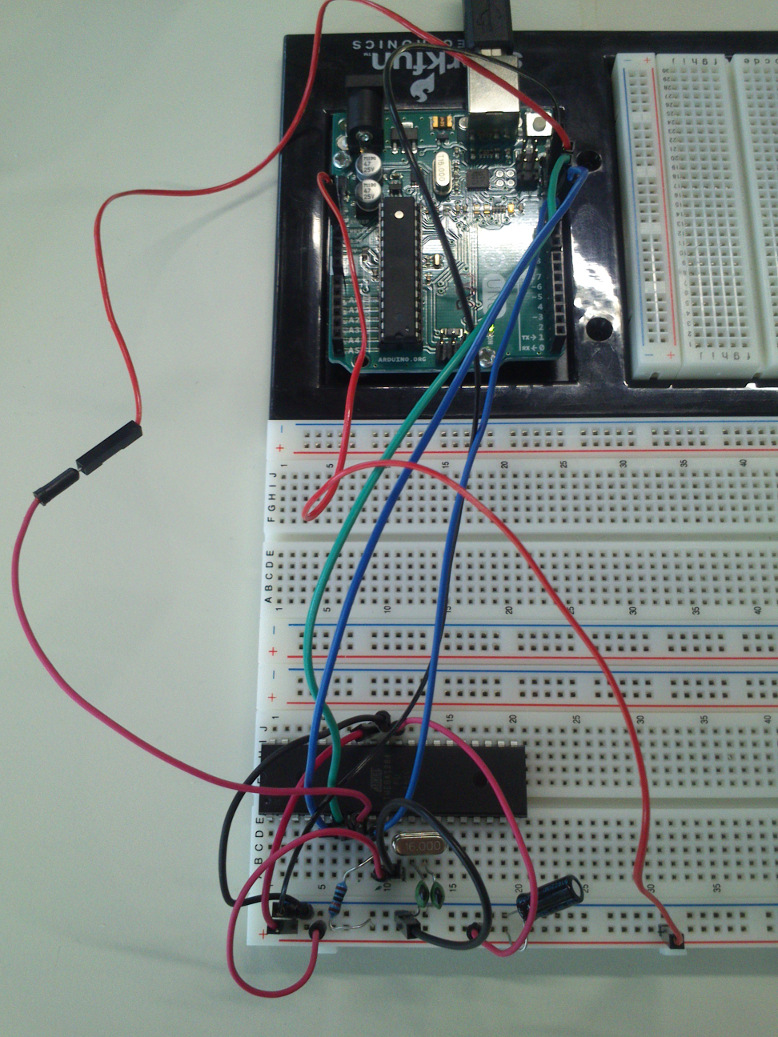
For wiring the ATmega1284P with the Arduino Uno, I followed these recommendations, but I did not wire the FTDI header this time. I also omitted the 100 nF capacitor between GND and 5V.

The Atmel ATmega1284P compares fairly well to the chip the Arduino Mega 2560 uses (the comparison table is taken from here):
        Feature         328P    1284P   2560P
        Price           $2,99   $4,66   $11,28
        RAM             2k      16k     8k
        Flash           32k     128k    256k
        EEPROM          1k      4k      4k
        UART            1       2       4
        IO Pins         23      32      86
        Interrupts      2       3       8
        Analog Inputs   6       8       16
I needed to add the hardware definition for the ATmega1284P to file boards.txt that the Arduino IDE is using. I followed this tutorial on the Arduino website and the one from above. I downloaded the ZIP file with the board hardware definitions and unpacked it. When I wanted to transfer the hardware definitions into file boards.txt I had a hard time locating it on my harddisk. I finally found it in "/Applications/Arduino.app/Contents/Java/hardware/arduino/avr/boards.txt" which is a considerably more complicated path than what is detailed in the tutorial from the Arduino website. Alternatively to finding the file from the shell, the file can be uncovered following the section "Manual Installation" from this Adafruit tutorial in which Adafruit details how to add hardware definitions for their Arduino compatible boards.
To show the new board definitions within the Arduino IDE, I reenacted their tutorial but with some modifications: I renamed the folder that I got by unpacking the ZIP file as "mighty-1284p" and added this to "Arduino.app/Contents/Java/hardware/". For clarification: the file structure inside the Arduino application, Arduino.app, can be accessed by right-clicking on it, then selecting "Show package Contents".
Burning the bootloader: I selected as board "Mighty 1284p 16MHz using Optiboot", selected as bootloader "Arduino as ISP" and tried to burn the bootloader with "Bootloader brennen" ("burn bootloader"). I got the following error message:
        Der Sketch verwendet 5.848 Bytes (4%) des Programmspeicherplatzes. Das Maximum sind 130.048 Bytes.
        Globale Variablen verwenden 665 Bytes des dynamischen Speichers.
        Fehler beim Hochladen: Konfigurationsparameter 'upload.tool' fehlt
This roughly translates to "Error while uploading: configuration parameter 'upload.tool' missing". This error is mostly due to the different Arduino IDE versions used in the tutorial(s) and by me. I fixed that error by adding the necessary parameter line '*.upload.tool=avrdude'
to every boards.txt definition in Arduino.app I could find, thereby replacing the asterisk with the respective board name. However, I believe this has been necessary for the boards.txt file in the folder "mighty1284-p/avr/" only, as after doing so the message disappeared. I was satisfied with this progress. The Arduino IDE was not. It greeted me with yet another error message:
            Warning: Board arduino:avr:bobuino doesn't define a 'build.board' preference. Auto-set to: AVR_BOBUINO
Warning: Board arduino:avr:mighty_opt doesn't define a 'build.board' preference. Auto-set to: AVR_MIGHTY_OPT
Warning: Board arduino:avr:mighty doesn't define a 'build.board' preference. Auto-set to: AVR_MIGHTY
Warning: Board arduino:avr:avr_developers doesn't define a 'build.board' preference. Auto-set to: AVR_AVR_DEVELOPERS
Warning: Board mighty-1284p:avr:mighty8 doesn't define a 'build.board' preference. Auto-set to: AVR_MIGHTY8
Warning: Board mighty-1284p:avr:avr_developers doesn't define a 'build.board' preference. Auto-set to: AVR_AVR_DEVELOPERS
Warning: Board mighty-1284p:avr:mighty_opt doesn't define a 'build.board' preference. Auto-set to: AVR_MIGHTY_OPT
Warning: Board mighty-1284p:avr:bobuino doesn't define a 'build.board' preference. Auto-set to: AVR_BOBUINO
Warning: Board mighty-1284p:avr:mighty doesn't define a 'build.board' preference. Auto-set to: AVR_MIGHTY
Bootloader-Datei angegeben, aber nicht vorhanden: /Applications/Arduino.app/Contents/Java/hardware/mighty-1284p/avr/bootloaders/ATmegaBOOT_1284P.hex

Der Sketch verwendet 5.848 Bytes (4%) des Programmspeicherplatzes. Das Maximum sind 129.024 Bytes.
Globale Variablen verwenden 665 Bytes des dynamischen Speichers.
avrdude: stk500_recv(): programmer is not responding
avrdude: stk500_getsync() attempt 1 of 10: not in sync: resp=0x00
avrdude: stk500_getsync() attempt 2 of 10: not in sync: resp=0x1c
avrdude: stk500_getsync() attempt 3 of 10: not in sync: resp=0x1c
avrdude: stk500_getsync() attempt 4 of 10: not in sync: resp=0x1c
avrdude: stk500_getsync() attempt 5 of 10: not in sync: resp=0x1c
avrdude: stk500_getsync() attempt 6 of 10: not in sync: resp=0x1c
avrdude: stk500_getsync() attempt 7 of 10: not in sync: resp=0x1c
avrdude: stk500_getsync() attempt 8 of 10: not in sync: resp=0x1c
avrdude: stk500_getsync() attempt 9 of 10: not in sync: resp=0x1c
avrdude: stk500_getsync() attempt 10 of 10: not in sync: resp=0x1c
Problem beim Hochladen auf das Board. Hilfestellung dazu unter http://www.arduino.cc/en/Guide/Troubleshooting#upload.
The Arduino IDE seems to expect yet another parameter line to be present in boards.txt. I added this line to the boards.txt files in "mighty-1284p/avr/" and everywhere else in Arduino.app (I know this is amateurish). The Arduino IDE also complains that it cannot find the bootloader in the path "/Applications/Arduino.app/Contents/Java/hardware/mighty-1284p/avr/bootloaders/ATmegaBOOT_1284P.hex." It seems the incompatible boards.txt file I downloaded is in an older format not suitable for an Arduino IDE 1.5+ (see this discussion on a German Arduino forum).
I copied the 'ATmegaBOOT_1284P.hex' file from folder 'mighty-1284p/bootloaders/standard/' to the location the Arduino IDE expected it to be. That worked.
When I tried to burn the bootloader now, I got a similar message as before that means yet another line, "*.bootloader.tool=avrdude" is missing in the board definition files. I added this line to all boards.txt files but still got another error:
avrdude: Yikes!  Invalid device signature.
         Double check connections and try again, or use -F to override
         this check.

Fehler beim Brennen des Bootloaders.
What device signature does the Arduino IDE expect? I don't know. I investigated a little bit and stumbled upon this Arduino forum entry. There, someone recommends to replace the device signature in the boards.txt file. My chip is an ATmega1284PU while the chip they are using in the tutorial I am following is an ATmega1284P. They have different device signatures. Could this be the source of my problem? But on this web page, someone shows the photo of an ATmega1284PU and its signature. The chip on the photo is "my" chip, and its signature is:
Atmega chip detector.
Entered programming mode OK.
Signature = 1E 97 05
Processor = ATmega1284P
Flash memory size = 131072
LFuse = 62
HFuse = 99
EFuse = FF
Lock byte = FF
Clock calibration = 81
Bootloader in use: No
EEPROM preserved through erase: No
Watchdog timer always on: No
Bootloader is 8192 bytes starting at 1E000

Bootloader: ...
It seems I need to investigate further. The author of the page also points me at some useful programs, the 'ATmega chip detector' for example that has produced above output. Grab them from here. I again checked all connections and tried again to burn the bootloader. Using the Arduino IDE's verbose mode, I learnt that it is likely that my chip is not recognized at all, as the line "Device signature = 0x000000" appears in below output.
    vrdude: Version 6.0.1, compiled on Apr 14 2015 at 16:30:25
         Copyright (c) 2000-2005 Brian Dean, http://www.bdmicro.com/
         Copyright (c) 2007-2009 Joerg Wunsch

         System wide configuration file is "/Applications/Arduino.app/Contents/Java/hardware/tools/avr/etc/avrdude.conf"
         User configuration file is "/Users/tlaubach/.avrduderc"
         User configuration file does not exist or is not a regular file, skipping

         Using Port                    : /dev/cu.usbmodemFD131
         Using Programmer              : stk500v1
         Overriding Baud Rate          : 19200
         AVR Part                      : ATmega1284P
         Chip Erase delay              : 55000 us
         PAGEL                         : PD7
         BS2                           : PA0
         RESET disposition             : dedicated
         RETRY pulse                   : SCK
         serial program mode           : yes
         parallel program mode         : yes
         Timeout                       : 200
         StabDelay                     : 100
         CmdexeDelay                   : 25
         SyncLoops                     : 32
         ByteDelay                     : 0
         PollIndex                     : 3
         PollValue                     : 0x53
         Memory Detail                 :

                                  Block Poll               Page                       Polled
           Memory Type Mode Delay Size  Indx Paged  Size   Size #Pages MinW  MaxW   ReadBack
           ----------- ---- ----- ----- ---- ------ ------ ---- ------ ----- ----- ---------
           eeprom        65    10   128    0 no       4096    8      0  9000  9000 0xff 0xff
           flash         65    10   256    0 yes    131072  256    512  4500  4500 0xff 0xff
           lock           0     0     0    0 no          1    0      0  9000  9000 0x00 0x00
           lfuse          0     0     0    0 no          1    0      0  9000  9000 0x00 0x00
           hfuse          0     0     0    0 no          1    0      0  9000  9000 0x00 0x00
           efuse          0     0     0    0 no          1    0      0  9000  9000 0x00 0x00
           signature      0     0     0    0 no          3    0      0     0     0 0x00 0x00
           calibration    0     0     0    0 no          1    0      0     0     0 0x00 0x00

         Programmer Type : STK500
         Description     : Atmel STK500 Version 1.x firmware
         Hardware Version: 2
         Firmware Version: 1.18
         Topcard         : Unknown
         Vtarget         : 0.0 V
         Varef           : 0.0 V
         Oscillator      : Off
         SCK period      : 0.1 us

avrdude: AVR device initialized and ready to accept instructions

Reading | ################################################## | 100% 0.03s

avrdude: Device signature = 0x000000 (retrying)

Reading | ################################################## | 100% 0.03s

avrdude: Device signature = 0x000000 (retrying)

Fehler beim Brennen des Bootloaders.
Reading | ################################################## | 100% 0.02s

avrdude: Device signature = 0x000000
avrdude: Yikes!  Invalid device signature.
         Double check connections and try again, or use -F to override
         this check.


avrdude done.  Thank you.
I added a stabilization capacitor between 5V and GND and verified all connections. I also pressed the chip firmly to the breadboard. This was the culprit. Don't tell anyone. This time the Arduino IDE recognized the chip's device signature, "0x1e9705" but insisted it is the wrong one. It expected "0x1e9706". I changed the signature to "0x1e9706" in file "avrdude.conf" from "Arduino.app/Contents/Java/hardware/tools/avr/etc/". In the Arduino forum and elsewhere, I have read that AVRdude sometimes expects a wrong device signature because the fuses have not been set before. Another opinion is that there might be noise in the electrical connections. One user reports that there was one MCU among many in his charge that reported a different device number than all other chips in his whole bunch. Nevertheless, after these modifications (...) the bootloader was burnt onto the ATmega1284PU:
/Applications/Arduino.app/Contents/Java/hardware/tools/avr/bin/avrdude -C/Applications/Arduino.app/Contents/Java/hardware/tools/avr/etc/avrdude.conf -v -patmega1284p -cstk500v1 -P/dev/cu.usbmodemFA141 -b19200 -e -Ulock:w:0x3F:m -Uefuse:w:0xfd:m -Uhfuse:w:0xde:m -Ulfuse:w:0xff:m

avrdude: Version 6.0.1, compiled on Apr 14 2015 at 16:30:25
         Copyright (c) 2000-2005 Brian Dean, http://www.bdmicro.com/
         Copyright (c) 2007-2009 Joerg Wunsch

         System wide configuration file is "/Applications/Arduino.app/Contents/Java/hardware/tools/avr/etc/avrdude.conf"
         User configuration file is "/Users/tlaubach/.avrduderc"
         User configuration file does not exist or is not a regular file, skipping

         Using Port                    : /dev/cu.usbmodemFA141
         Using Programmer              : stk500v1
         Overriding Baud Rate          : 19200
         AVR Part                      : ATmega1284P
         Chip Erase delay              : 55000 us
         PAGEL                         : PD7
         BS2                           : PA0
         RESET disposition             : dedicated
         RETRY pulse                   : SCK
         serial program mode           : yes
         parallel program mode         : yes
         Timeout                       : 200
         StabDelay                     : 100
         CmdexeDelay                   : 25
         SyncLoops                     : 32
         ByteDelay                     : 0
         PollIndex                     : 3
         PollValue                     : 0x53
         Memory Detail                 :

                                  Block Poll               Page                       Polled
           Memory Type Mode Delay Size  Indx Paged  Size   Size #Pages MinW  MaxW   ReadBack
           ----------- ---- ----- ----- ---- ------ ------ ---- ------ ----- ----- ---------
           eeprom        65    10   128    0 no       4096    8      0  9000  9000 0xff 0xff
           flash         65    10   256    0 yes    131072  256    512  4500  4500 0xff 0xff
           lock           0     0     0    0 no          1    0      0  9000  9000 0x00 0x00
           lfuse          0     0     0    0 no          1    0      0  9000  9000 0x00 0x00
           hfuse          0     0     0    0 no          1    0      0  9000  9000 0x00 0x00
           efuse          0     0     0    0 no          1    0      0  9000  9000 0x00 0x00
           signature      0     0     0    0 no          3    0      0     0     0 0x00 0x00
           calibration    0     0     0    0 no          1    0      0     0     0 0x00 0x00

         Programmer Type : STK500
         Description     : Atmel STK500 Version 1.x firmware
         Hardware Version: 2
         Firmware Version: 1.18
         Topcard         : Unknown
         Vtarget         : 0.0 V
         Varef           : 0.0 V
         Oscillator      : Off
         SCK period      : 0.1 us

avrdude: AVR device initialized and ready to accept instructions

Reading | ################################################## | 100% 0.03s

avrdude: Device signature = 0x1e9706
avrdude: erasing chip
avrdude: reading input file "0x3F"
avrdude: writing lock (1 bytes):

/Applications/Arduino.app/Contents/Java/hardware/tools/avr/bin/avrdude -C/Applications/Arduino.app/Contents/Java/hardware/tools/avr/etc/avrdude.conf -v -patmega1284p -cstk500v1 -P/dev/cu.usbmodemFA141 -b19200 -Uflash:w:/Applications/Arduino.app/Contents/Java/hardware/mighty-1284p/avr/bootloaders/optiboot_atmega1284p.hex:i -Ulock:w:0x0F:m
Writing | ################################################## | 100% 0.01s

avrdude: 1 bytes of lock written
avrdude: verifying lock memory against 0x3F:
avrdude: load data lock data from input file 0x3F:
avrdude: input file 0x3F contains 1 bytes
avrdude: reading on-chip lock data:

Reading | ################################################## | 100% 0.01s

avrdude: verifying ...
avrdude: 1 bytes of lock verified
avrdude: reading input file "0xfd"
avrdude: writing efuse (1 bytes):

Writing | ################################################## | 100% 0.01s

avrdude: 1 bytes of efuse written
avrdude: verifying efuse memory against 0xfd:
avrdude: load data efuse data from input file 0xfd:
avrdude: input file 0xfd contains 1 bytes
avrdude: reading on-chip efuse data:

Reading | ################################################## | 100% 0.01s

avrdude: verifying ...
avrdude: 1 bytes of efuse verified
avrdude: reading input file "0xde"
avrdude: writing hfuse (1 bytes):

Writing | ################################################## | 100% 0.01s

avrdude: 1 bytes of hfuse written
avrdude: verifying hfuse memory against 0xde:
avrdude: load data hfuse data from input file 0xde:
avrdude: input file 0xde contains 1 bytes
avrdude: reading on-chip hfuse data:

Reading | ################################################## | 100% 0.01s

avrdude: verifying ...
avrdude: 1 bytes of hfuse verified
avrdude: reading input file "0xff"
avrdude: writing lfuse (1 bytes):

Writing | ################################################## | 100% 0.01s

avrdude: 1 bytes of lfuse written
avrdude: verifying lfuse memory against 0xff:
avrdude: load data lfuse data from input file 0xff:
avrdude: input file 0xff contains 1 bytes
avrdude: reading on-chip lfuse data:

Reading | ################################################## | 100% 0.01s

avrdude: verifying ...
avrdude: 1 bytes of lfuse verified

avrdude done.  Thank you.


avrdude: Version 6.0.1, compiled on Apr 14 2015 at 16:30:25
         Copyright (c) 2000-2005 Brian Dean, http://www.bdmicro.com/
         Copyright (c) 2007-2009 Joerg Wunsch

         System wide configuration file is "/Applications/Arduino.app/Contents/Java/hardware/tools/avr/etc/avrdude.conf"
         User configuration file is "/Users/tlaubach/.avrduderc"
         User configuration file does not exist or is not a regular file, skipping

         Using Port                    : /dev/cu.usbmodemFA141
         Using Programmer              : stk500v1
         Overriding Baud Rate          : 19200
         AVR Part                      : ATmega1284P
         Chip Erase delay              : 55000 us
         PAGEL                         : PD7
         BS2                           : PA0
         RESET disposition             : dedicated
         RETRY pulse                   : SCK
         serial program mode           : yes
         parallel program mode         : yes
         Timeout                       : 200
         StabDelay                     : 100
         CmdexeDelay                   : 25
         SyncLoops                     : 32
         ByteDelay                     : 0
         PollIndex                     : 3
         PollValue                     : 0x53
         Memory Detail                 :

                                  Block Poll               Page                       Polled
           Memory Type Mode Delay Size  Indx Paged  Size   Size #Pages MinW  MaxW   ReadBack
           ----------- ---- ----- ----- ---- ------ ------ ---- ------ ----- ----- ---------
           eeprom        65    10   128    0 no       4096    8      0  9000  9000 0xff 0xff
           flash         65    10   256    0 yes    131072  256    512  4500  4500 0xff 0xff
           lock           0     0     0    0 no          1    0      0  9000  9000 0x00 0x00
           lfuse          0     0     0    0 no          1    0      0  9000  9000 0x00 0x00
           hfuse          0     0     0    0 no          1    0      0  9000  9000 0x00 0x00
           efuse          0     0     0    0 no          1    0      0  9000  9000 0x00 0x00
           signature      0     0     0    0 no          3    0      0     0     0 0x00 0x00
           calibration    0     0     0    0 no          1    0      0     0     0 0x00 0x00

         Programmer Type : STK500
         Description     : Atmel STK500 Version 1.x firmware
         Hardware Version: 2
         Firmware Version: 1.18
         Topcard         : Unknown
         Vtarget         : 0.0 V
         Varef           : 0.0 V
         Oscillator      : Off
         SCK period      : 0.1 us

avrdude: AVR device initialized and ready to accept instructions

Reading | ################################################## | 100% 0.02s

avrdude: Device signature = 0x1e9706
avrdude: NOTE: "flash" memory has been specified, an erase cycle will be performed
         To disable this feature, specify the -D option.
avrdude: erasing chip
avrdude: reading input file "/Applications/Arduino.app/Contents/Java/hardware/mighty-1284p/avr/bootloaders/optiboot_atmega1284p.hex"
avrdude: writing flash (130556 bytes):

Writing | ################################################## | 100% 0.42s

avrdude: 130556 bytes of flash written
avrdude: verifying flash memory against /Applications/Arduino.app/Contents/Java/hardware/mighty-1284p/avr/bootloaders/optiboot_atmega1284p.hex:
avrdude: load data flash data from input file /Applications/Arduino.app/Contents/Java/hardware/mighty-1284p/avr/bootloaders/optiboot_atmega1284p.hex:
avrdude: input file /Applications/Arduino.app/Contents/Java/hardware/mighty-1284p/avr/bootloaders/optiboot_atmega1284p.hex contains 130556 bytes
avrdude: reading on-chip flash data:

Reading | ################################################## | 100% 0.26s

avrdude: verifying ...
avrdude: 130556 bytes of flash verified
avrdude: reading input file "0x0F"
avrdude: writing lock (1 bytes):

Writing | ################################################## | 100% 0.02s

avrdude: 1 bytes of lock written
avrdude: verifying lock memory against 0x0F:
avrdude: load data lock data from input file 0x0F:
avrdude: input file 0x0F contains 1 bytes
avrdude: reading on-chip lock data:

Reading | ################################################## | 100% 0.01s

avrdude: verifying ...
avrdude: 1 bytes of lock verified

avrdude done.  Thank you.
Now, Daniele, I hear your laughter... :-)
Turning the ATmega1284P into an Arduino-compatible microcontroller: I am now going to program the
ATmega1284P using the Arduino Uno. I will add a LED to the design and try the Blink sketch from the examples. I opened the Blink sketch, changed the pin number to 1 and selected "Sketch/Hochladen mit Programmer" (engl. "Sketch/Upload using Programmer"). This is in boldface because I did this the wrong way. As usual, the Arduino IDE complained about the device number. In file avrdude.conf, I changed it into "signature = 0x1e 0x97 0x06;" and uploaded the Blink sketch. The LED did was not lit. By experimenting, I found out that I need to use digital pin 9 in the sketch, contrary to what is stated in the tutorial. Digital pin 9 on the "Arduino" side corresponds to MCU pin 2 of the ATmega1284P to which the LED is attached (see above circuit schematic). Apart from my feeling of success, I do not understand the deviation between the expected and the reported device number.
    Applications/Arduino.app/Contents/Java/hardware/tools/avr/bin/avrdude -C/Applications/Arduino.app/Contents/Java/hardware/tools/avr/etc/avrdude.conf -v -patmega1284p -cstk500v1 -P/dev/cu.usbmodemFA141 -b19200 -Uflash:w:/var/folders/37/bk665qlx7rq8s2r4bq8sq7sr0000gn/T/buildd5ae82e677127ac286f51de66781d807.tmp/Blink.ino.hex:i

avrdude: Version 6.0.1, compiled on Apr 14 2015 at 16:30:25
         Copyright (c) 2000-2005 Brian Dean, http://www.bdmicro.com/
         Copyright (c) 2007-2009 Joerg Wunsch

         System wide configuration file is "/Applications/Arduino.app/Contents/Java/hardware/tools/avr/etc/avrdude.conf"
         User configuration file is "/Users/tlaubach/.avrduderc"
         User configuration file does not exist or is not a regular file, skipping

         Using Port                    : /dev/cu.usbmodemFA141
         Using Programmer              : stk500v1
         Overriding Baud Rate          : 19200
         AVR Part                      : ATmega1284P
         Chip Erase delay              : 55000 us
         PAGEL                         : PD7
         BS2                           : PA0
         RESET disposition             : dedicated
         RETRY pulse                   : SCK
         serial program mode           : yes
         parallel program mode         : yes
         Timeout                       : 200
         StabDelay                     : 100
         CmdexeDelay                   : 25
         SyncLoops                     : 32
         ByteDelay                     : 0
         PollIndex                     : 3
         PollValue                     : 0x53
         Memory Detail                 :

                                  Block Poll               Page                       Polled
           Memory Type Mode Delay Size  Indx Paged  Size   Size #Pages MinW  MaxW   ReadBack
           ----------- ---- ----- ----- ---- ------ ------ ---- ------ ----- ----- ---------
           eeprom        65    10   128    0 no       4096    8      0  9000  9000 0xff 0xff
           flash         65    10   256    0 yes    131072  256    512  4500  4500 0xff 0xff
           lock           0     0     0    0 no          1    0      0  9000  9000 0x00 0x00
           lfuse          0     0     0    0 no          1    0      0  9000  9000 0x00 0x00
           hfuse          0     0     0    0 no          1    0      0  9000  9000 0x00 0x00
           efuse          0     0     0    0 no          1    0      0  9000  9000 0x00 0x00
           signature      0     0     0    0 no          3    0      0     0     0 0x00 0x00
           calibration    0     0     0    0 no          1    0      0     0     0 0x00 0x00

         Programmer Type : STK500
         Description     : Atmel STK500 Version 1.x firmware
         Hardware Version: 2
         Firmware Version: 1.18
         Topcard         : Unknown
         Vtarget         : 0.0 V
         Varef           : 0.0 V
         Oscillator      : Off
         SCK period      : 0.1 us

avrdude: AVR device initialized and ready to accept instructions

Reading | ################################################## | 100% 0.03s

avrdude: Device signature = 0x1e9706
avrdude: NOTE: "flash" memory has been specified, an erase cycle will be performed
         To disable this feature, specify the -D option.
avrdude: erasing chip
avrdude: reading input file "/var/folders/37/bk665qlx7rq8s2r4bq8sq7sr0000gn/T/buildd5ae82e677127ac286f51de66781d807.tmp/Blink.ino.hex"
avrdude: writing flash (1072 bytes):

Writing | ################################################## | 100% 2.09s

avrdude: 1072 bytes of flash written
avrdude: verifying flash memory against /var/folders/37/bk665qlx7rq8s2r4bq8sq7sr0000gn/T/buildd5ae82e677127ac286f51de66781d807.tmp/Blink.ino.hex:
avrdude: load data flash data from input file /var/folders/37/bk665qlx7rq8s2r4bq8sq7sr0000gn/T/buildd5ae82e677127ac286f51de66781d807.tmp/Blink.ino.hex:
avrdude: input file /var/folders/37/bk665qlx7rq8s2r4bq8sq7sr0000gn/T/buildd5ae82e677127ac286f51de66781d807.tmp/Blink.ino.hex contains 1072 bytes
avrdude: reading on-chip flash data:

Reading | ################################################## | 100% 1.29s

avrdude: verifying ...
avrdude: 1072 bytes of flash verified

avrdude done.  Thank you.
The configuration section for the ATmega1284p in avrdude.conf now begins like this:
#------------------------------------------------------------
# ATmega1284P
#------------------------------------------------------------

# similar to ATmega164p

part
    id               = "m1284p";
    desc             = "ATmega1284P";
    has_jtag         = yes;
    stk500_devcode   = 0x82; # no STK500v1 support, use the ATmega16 one
    avr910_devcode   = 0x74;
    signature        = 0x1e 0x97 0x06;
    pagel            = 0xd7;
Driving the Adafruit 32x32 LED RGB matrix panel with the ATmega1284P
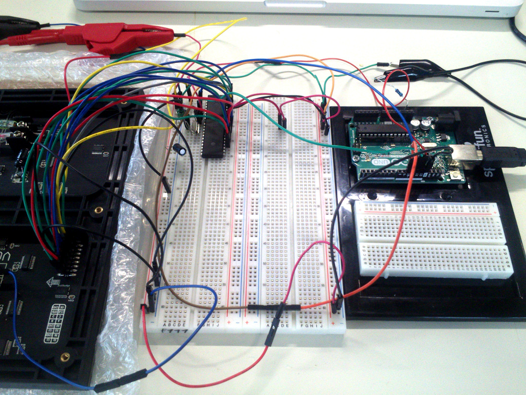
This is the next essential step for my final project, at least if I really want the memory the ATmega1284P offers in comparison with the ATmega328P. The libraries for the LED matrix panel have been tailored to the Arduino Uno and the Arduino Mega 2560 only. I am now going to check whether I can use these libraries. I have learnt from my assignment on Output Devices that I need to link all wires between the LED matrix and the Arduino.
First I needed a pin assignment table that translates between the Arduino Uno's pin mapping and the MCU pins of the ATmega1284P. I found below diagram here and some words about Arduino Library compatibility there. It seems someone else has had similar ideas that they condensed into their product "Arduino Pro"...
I tried to run the LED matrix panel with this pin assignment, but it did not work.
I checked my cabling, measured the wires, rechecked everything, but to no avail.
Finally I had a fresh look at Maniacbug's website and realized that this guy has used an individual pin assignment. According to him, nearly anyone who makes a project with an AT1284p uses his/her own pin assignment. This is his pin assignment I will be going to use from now on:
                      +---\/---+
           (D 0) PB0 1|        |40 PA0 (AI 0 / D24)
           (D 1) PB1 2|        |39 PA1 (AI 1 / D25)
      INT2 (D 2) PB2 3|        |38 PA2 (AI 2 / D26)
       PWM (D 3) PB3 4|        |37 PA3 (AI 3 / D27)
    PWM/SS (D 4) PB4 5|        |36 PA4 (AI 4 / D28)
      MOSI (D 5) PB5 6|        |35 PA5 (AI 5 / D29)
  PWM/MISO (D 6) PB6 7|        |34 PA6 (AI 6 / D30)
   PWM/SCK (D 7) PB7 8|        |33 PA7 (AI 7 / D31)
                 RST 9|        |32 AREF
                VCC 10|        |31 GND
                GND 11|        |30 AVCC
              XTAL2 12|        |29 PC7 (D 23)
              XTAL1 13|        |28 PC6 (D 22)
      RX0 (D 8) PD0 14|        |27 PC5 (D 21) TDI
      TX0 (D 9) PD1 15|        |26 PC4 (D 20) TDO
RX1/INT0 (D 10) PD2 16|        |25 PC3 (D 19) TMS
TX1/INT1 (D 11) PD3 17|        |24 PC2 (D 18) TCK
     PWM (D 12) PD4 18|        |23 PC1 (D 17) SDA
     PWM (D 13) PD5 19|        |22 PC0 (D 16) SCL
     PWM (D 14) PD6 20|        |21 PD7 (D 15) PWM
                      +--------+
I tried this pin assignment, but the LED matrix panel still did not work. I searched the web for more information on the mighty1284p. After eons, I read about a new version of this library by Jack Christensen here. I replaced my old library version by his one in Arduino.app. The matrix panel now works! Christensen has made those changes to the library I had done to the original one, but some more additional tweaks that I had not anticipated. However, I am glad that I can go on with my work now. For the LED matrix panel, I used following cabling, with above pin assignment as basis:
CLK     Digital pin 0
OE      Digital pin 29
LAT     Digital pin 28
A       Analog pin A0
B       Analog pin A1
C       Analog pin A2
D       Analog pin A3

R1      Digital pin 18
G1      Digital pin 19
B1      Digital pin 20
R2      Digital pin 21
G2      Digital pin 22
B2      Digital pin 23
Source files
Files for the section 'ATmega1284p and LED matrix panel': hereAtmel ATmega1284p datasheet: here