Week 2: Computer-aided Design
Homework for this week:
- Get comfortable with a Bitmap drawing tool: draw outlines.
- Make diagrams for your final project in a vector drawing program.
- Draw simple and high-end CAD designs for your project.
- Model the geometry of your project.
- Make high-quality renderings of your final project, i.e., with Blender.
- If time permits, make a video clip, use a Game Engine to interactively operate your project.
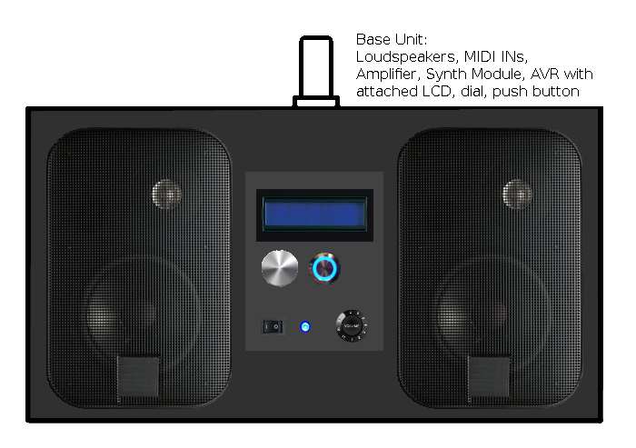
Old project: Electronic Music at a campfire
Below image (get it from here) shows a drawing of the front and back of the Base Unit. I made it with GIMP. GIMP is an open-source bitmap drawing tool that is in many ways similar to Adobe Photoshop. The loudspeakers are the omnipresent JBL Control 1 as I have two pairs of them at home. I borrowed the images of the loudspeakers from a website, manually separated them from their background by placing pixels in suitable colors. Likewise, I obtained the remaining components in the image. Some of them I had to scale to size. I put all elements on a background in dark grey. I would have benefitted had I known how to use layers in GIMP. I want to learn this in the future. I added the text with the Text Tool.
Final Project: Arduino-based Arcade Video Game System
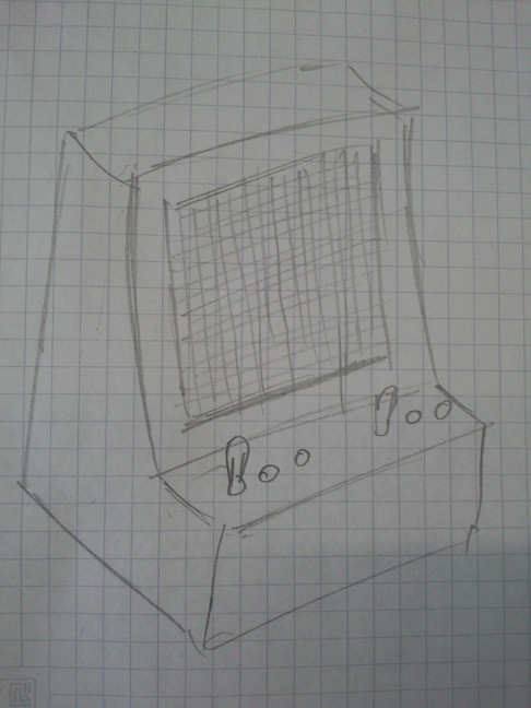
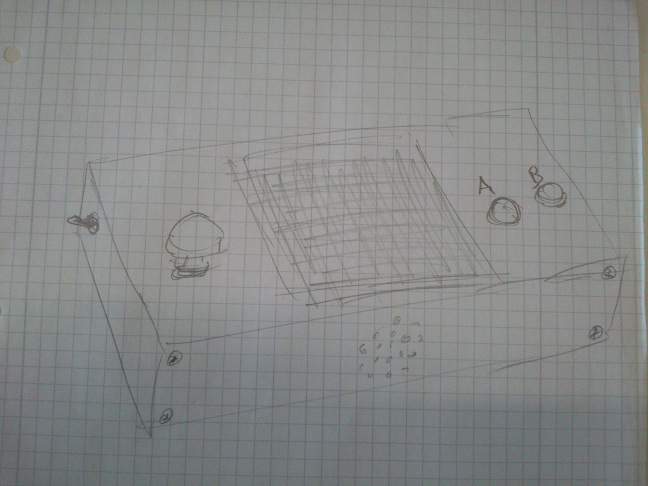
I was thinking about different designs for my video game system. One was a design that is a cross between that of the Atari VCS and a Korg MS-20 synthesizer, both from the Seventies. The other is a handheld. I have drawn these pictures:
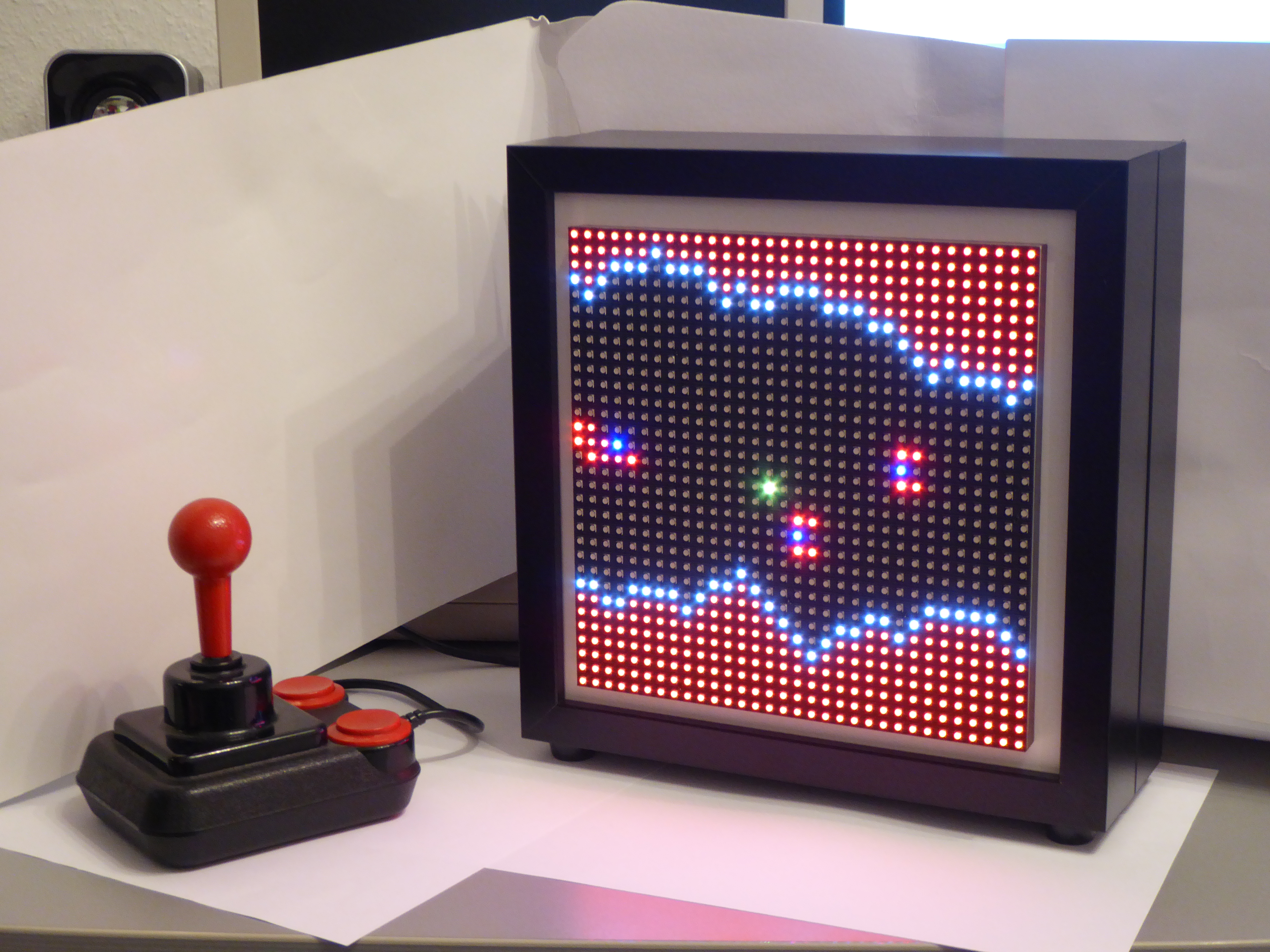
For the LEDmePlay that I would be going to improve in my final project, I made a flyer that we spread at the Maker Faire Hannover at the end of May, 2015:
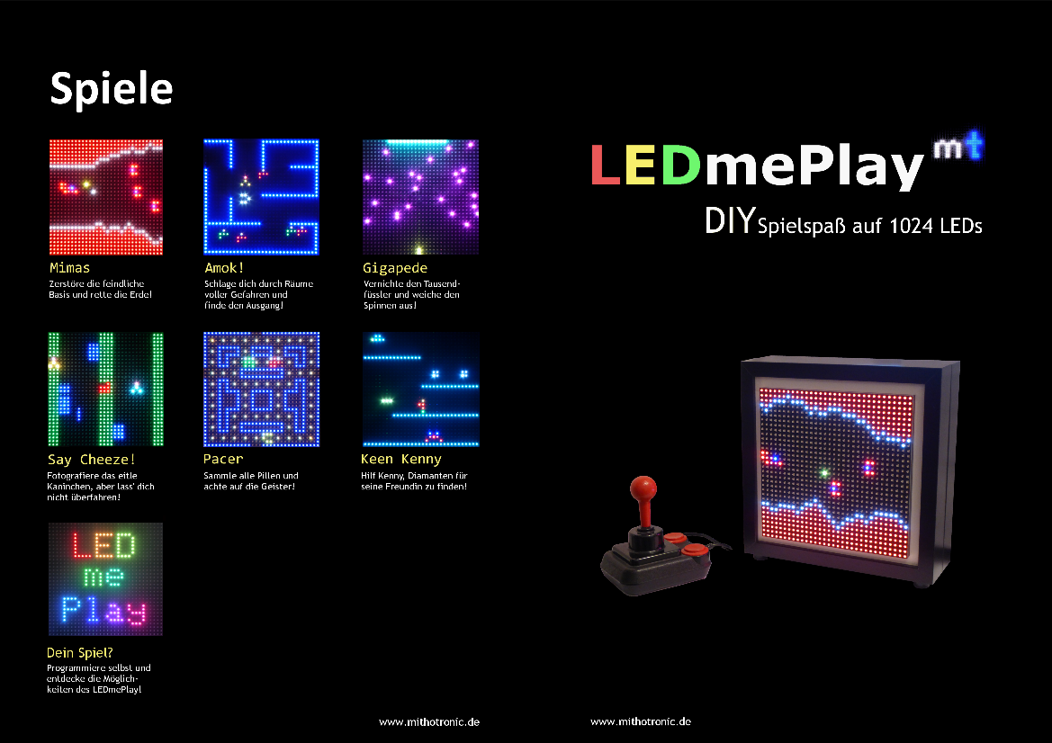
My friend and I took the "screenshots" from the games under dark lighting conditions and a camera stand. Some shots we did on a picture frame with a glass pane, others on a frame without glass pane. I imported the RAW camera images into GIMP, exported them to the PNG format and shrunk them all to the same dimension. I put them on a uniformly black background. I placed the lettering manually and copied its style over and over for each text section.
For the motif that features the Competition Pro joystick and the LEDmePlay in two Ribba picture frames, I took the photograph from file "P1070061.JPG". It would be necessary to separate the foreground from the background. For this, I modified the pixels close to the boarders of the console and the joystick and darkened some sections to make them fit in with the black background. Once done, I used GIMP's "Auswahlwerkzeug/Freie Auswahl" ("Free Selection") tool to copy only the object. I then copied the joystick and the console over into a fresh image. Where appropriate, I used reference lines at which I aligned the images, text boxes and objects. The files "P1070061.JPG" and "LEDmePlay_Pacer.jpg" are "screenshots" of two of the game scenes that would appear in the flyer. I needed to scale all screenshots to a uniform size and place them in a grid. The GIMP file "Spiele.xcf" represents an intermediate stage. The files "Entwurf1_....xcf" are early versions of the inner and outer pages of the flyer.
Inkscape: Component Diagram for my final project
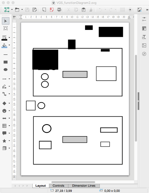
The electronics for my final project shall consist of two systems, each with its own microcontroller board. Both are based on the Atmel ATmega1284p. In the diagram, I wanted to visualize the flow of information with arrows, i.e., input devices produce data that go into the device, output devices produce output that is built from data that the device has sent to them.
In Inkscape, I drew the foundation for my diagram, see file "VGS_functionDiagram.svg" at the end of the page.
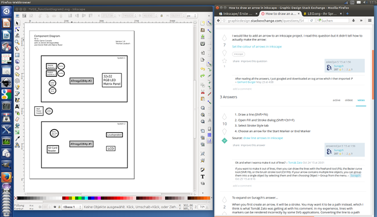
I did not find a possibility to draw arrows, as Inkscape did not seem to offer them. I found tutorials for this matter on the WWW (cf. above image), but they seemed copious. They let you make a shape, or first draw a path, set the stroke style, choose the direction of the arrow, unify two paths, convert an outline to a path, and so on. I believe I am spoiled by OpenOffice/LibreOffice and Microsoft PowerPoint, as they let me use arrows upon a mouse click. Anyway, I imported the SVG from Inkscape in LibreOffice and expected to be finished within a minute...or so I thought. I got this:
This meant I would need to learn the cumbersome way of obtaining arrows in Inkscape. While working, I realized that the method is not hard at all. I used the succession of steps "Draw straight (poly)line, finish line with Enter, open 'Filling and Contour', select the type of line ending". In this situation it confused me that, when I selected an arrow that points in the right direction, it was always added at the opposite end of the line. Since then I drew my lines in the opposite direction. Finally I discovered pull-down menus in the "Filling and Contour" menu that let you choose patterns for the start and end of a line. All's right with the world.
When I had finished the arrows in the upper part of the diagram, I copied one arrow to the lower part. It was copied correctly but distorted. I deleted the lower arrow and drew it by hand.
For the arrows to be straight, I made use of the Control key.

Reproduced from week 7, "Computer-controlled Machining"
Design of a synthesizer stand with Autodesk Fusion 360
For the assignment on Computer-controlled machining we should design something big for a CNC milling cutter. As my fairly big thing, I decided to make a wooden stand for one of my synthesizers, the
Waldorf Blofeld Keyboard.
In the past, I briefly looked at the 3D modeling software Rhinoceros which
I think is not easy to master. For this week's work, our fab group started to use Autodesk Fusion 360.
We like it because the guys behind the program offer some great tutorials on YouTube. Moreover, the program
is widely appreciated. After I had learned how to build a simple yet usable laptop stand in
this tutorial, I made my own
parametric design for a stand
without dog bones and the same one
laid flat with dog bones.
Parameterization
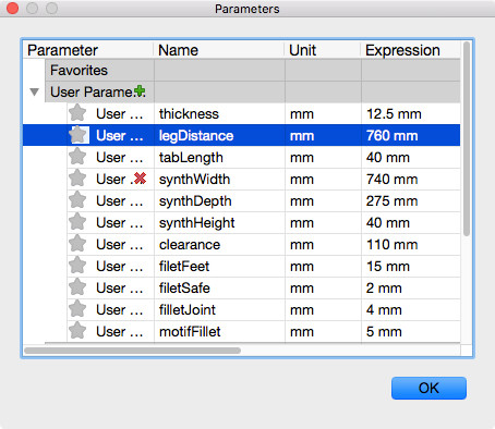
In order to allow for a design that I can change to my heart's content, I used the parameters as shown in
fig. 7.
- thickness Material thickness
- legDistance Inner distance between the legs
- tabLength Length of the tabs in the top plate
- synthWidth Width of the synthesizer
- synthDepth Depth of the synthesizer
- synthHeight Height of the synthesizer at its front
- clearance Distance between table top and plate
- filetFeet Radius of the fillets at the legs
- filetSafe Radius of the safety fillets (fillets at sharp edges)
- filletJoint Radius of the fillets at the joints
- motifFillet Radius of the fillets in the motif in the plate
Design process
I first changed the coordinate system such that the Z-axis goes upward: Preferences/General/Default Modeling Orientation = Up,
as this is the orientation I did my first steps with in the laptop stand tutorial. I cannot detail all steps here precisely. However, I will mention the most important steps that got stuck in my brain.
I first designed a leg. For this, I made a rough sketch of a leg out of straight lines. I set constraints,
for example, I made the top and bottom line parallel, declared some angles a right angle. I also added dimensions to the sketch
such as the length of the line that would later on be the base line for the top plate. Then I did the fillets which gave the leg
a pleasant style, just for eye candy. As already mentioned, for some dimensions I used parameters so to be able to build stands for
different instruments.
I left the sketch view and extruded the sketch (Create/Extrude), effectively adding a parametric depth to it. I ended up with one leg
that I needed to duplicate. For this, I clicked the top component in Fusion 360's browser and activated it.
From there, I selected my newly created component, the first leg, and copied and pasted it in place. Duplicating components this way
is important, as I want them to be logically linked and individual components, each of which with its individual history.
I established a logical joint between the legs' faces that face each other. I set their distance using parameter legDistance.
The grasp of the component hierarchy and to which extent the individual component histories depend on it is, for me, one of the important lessons to learn with Fusion 360.
Next I designed a sketch for the top plate. I did not draw the sketch directly on the top face of one of the legs but on a separate
plane. Prior to this I created a new component for the plate. Once the rough outline was finished, I again set constraints, dimensioning and parameterizing some distances.
The plate would have holes for tabs. I found the position for the tabs using construction lines (draw a line, click on it, press 'x')
and the mirror tool. I made the plane with the sketch aligned to the top face of the legs (Modify/Align). I left sketch view and
extruded the plate downward by the parameter thickness, doing so cutting the tabs from the legs.
I got the necessary holes in the top plate by performing a subtraction operation (Modify/Combine with operation "Cut").
For stability, I wanted a support sandwiched between the top plate and the legs. I first created a new component for the support.
Then, I designed an offset plane to the plane through the top faces of the tabs. Then I projected the silhouettes of the legs onto the plane (Sketch/Project).
On the offset plane, I drew a sketch for the support, concretely a rectangle with a width that is the distance between the two legs. Its height equals the thickness of the Multiplex
I would be using. This is identical to parameter thickness. I wanted the top faces of the support and the top faces of the legs making one smooth surface. For this, the
support would have an opening about at its lower part with half the height of the support. The top face of the legs would have tabs that fit to these openings.
For the openings, I added rectangles with thickness as width and half the height of the support as height.
I left sketch mode and extruded the rectangle downwards four centimeters, but omitting the rectangle for the opening in the support.
Finally, I added two additional supports at the back of the construction.
For the upper support, I constructed the corresponding sketch on an offset plane that I made parallel to the lower 'horizontal' edge of the leg.
The middle line of the support, seen from aside, would be colinear with the lower 'horizontal' edge of the leg. For the alignment, I used construction lines.
Like before, I extruded the rectangle that were the base area for the support and subtracted the resulting body from the leg's material.
For the lower support, I made a mistake. Instead of creating a new component, I copied the upper support and moved it at its new position.
While the result is usable, the lower support does not appear as an individual component in my design. Instead, it is hierarchically assigned to the upper support.
Eye candy on the top plate
As I like electronic music, and since the stand is meant for a synthesizer, I wanted a nice design for the top plate.
I activated the top plate component and created a plane on it, on which I drew a sketch. The sine-like curve consists of several splines.
The curve on the lower left is made of splines and demanded some manual tweaking. The PWM-like curve on the lower right is made of straight lines. I inserted
fillets at every 90° angle with radius motifFillet.
Dog bones
At places with 90° angles in a design, dog bones are a necessity. You obtain dog bones by adding drill holes with approximately half the diameter of the milling head,
their midpoint being the corner of the 90° angle. With dog bones, you allow the milling head to change its direction at the right position when it is already within
the work piece.
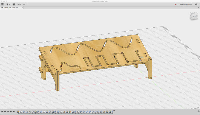
Fillets
In the whole design, see fig. 8, I added fillets with a parameterized radius to all sharp corners, so to prevent injury, and some fillets just for the sake of prettiness.
Preparing for CAM
For the CAM process, the holes for the dog bones, the inner contours and the outer contours need to be separated as they require
different tool paths. For this, many 3D modeling applications offer layers. Unfortunately, Fusion 360 does not.
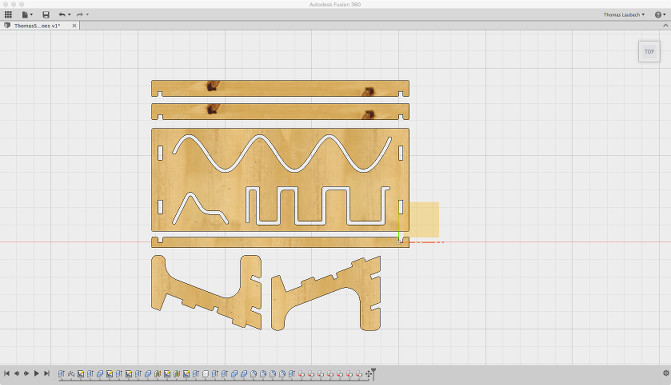
Instead, the strategy I followed in Fusion 360 was this: I laid all components in my design flat on the same surface (cf. fig. 9), with their best side all on top.
After that, I exported the
result in DXF format,
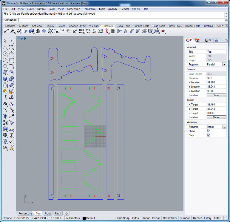
then re-opened the file in Rhinoceros. There I sent the holes and the outer and the inner contours onto separate, individually colored layers.
The result is displayed in fig. 10.
Animation of my Synth Stand in Blender
I made a short 3D animation of my synthesizer stand from the assignment on computer-controlled machining in Blender. I got the wood texture from www.textures.com. In Fusion 360, I exported every body of my stand one after another in format STL. I then imported all bodies into Blender, one after another. Since Blender maintains the original location of the body, I was not required to move bodies around in Blender.
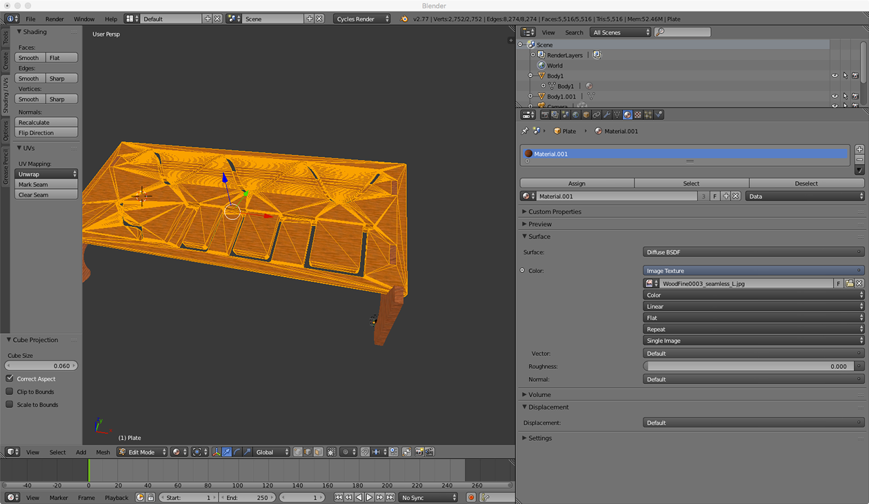
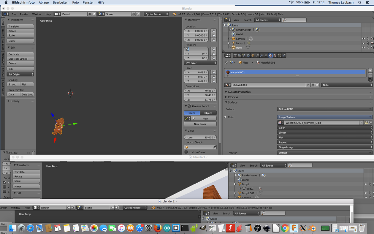
The next image shows the synth stand in Blender. I had imported the legs before and assigned a wood texture to them.
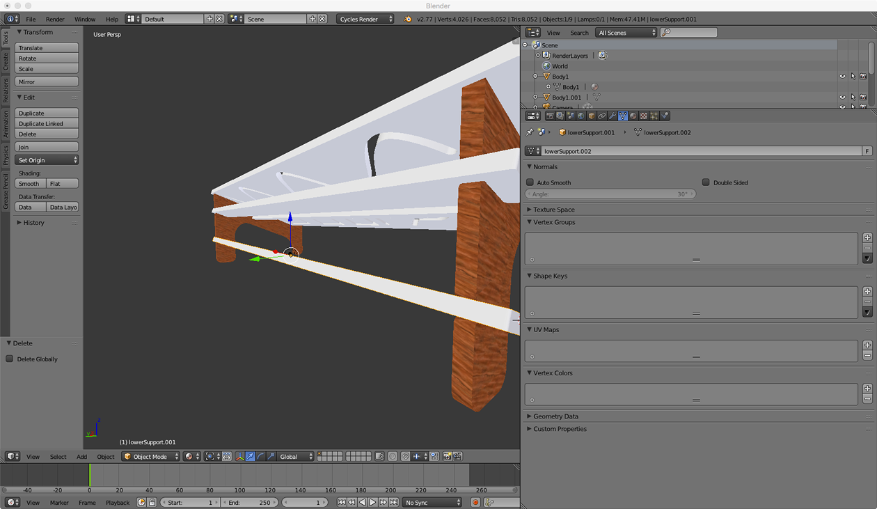
The texture can be scaled to pretty much any size. For this, some sort of mesh is displayed that helps to "wrap" the 2D texture in three dimensions. Too coarse a wood texture makes no sense, as the grain needs to be fine enough.
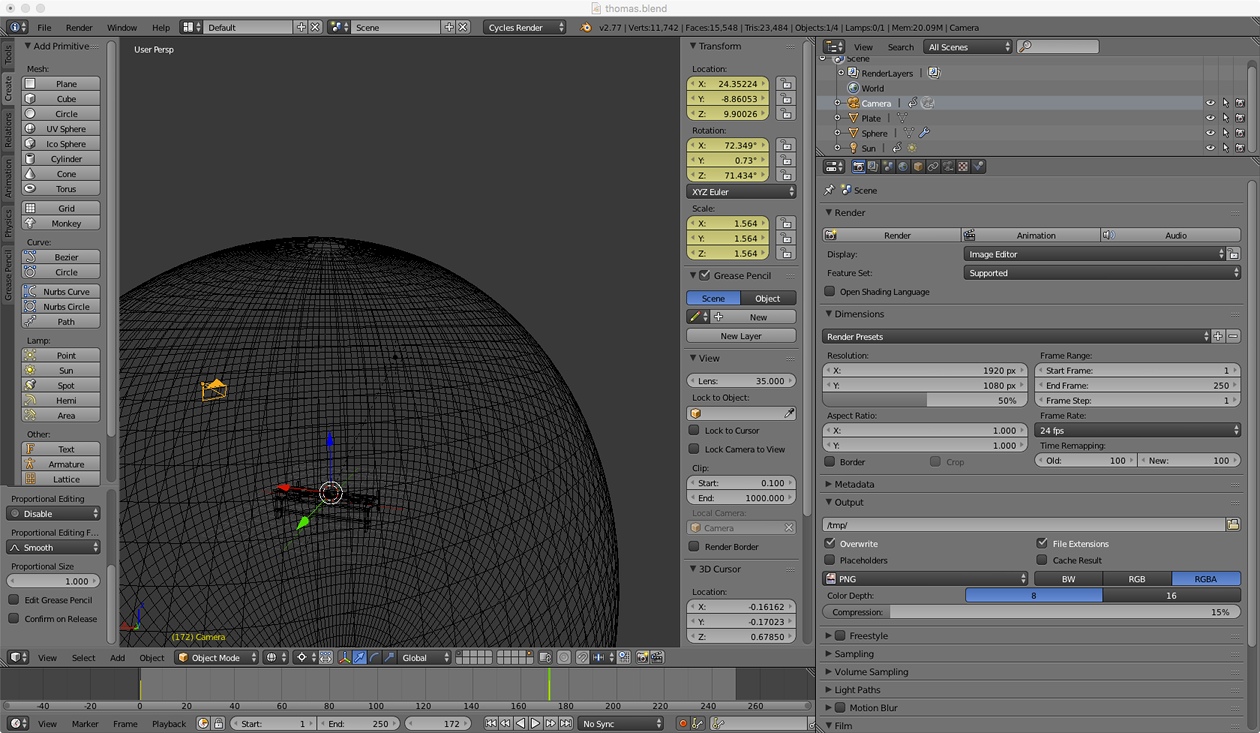
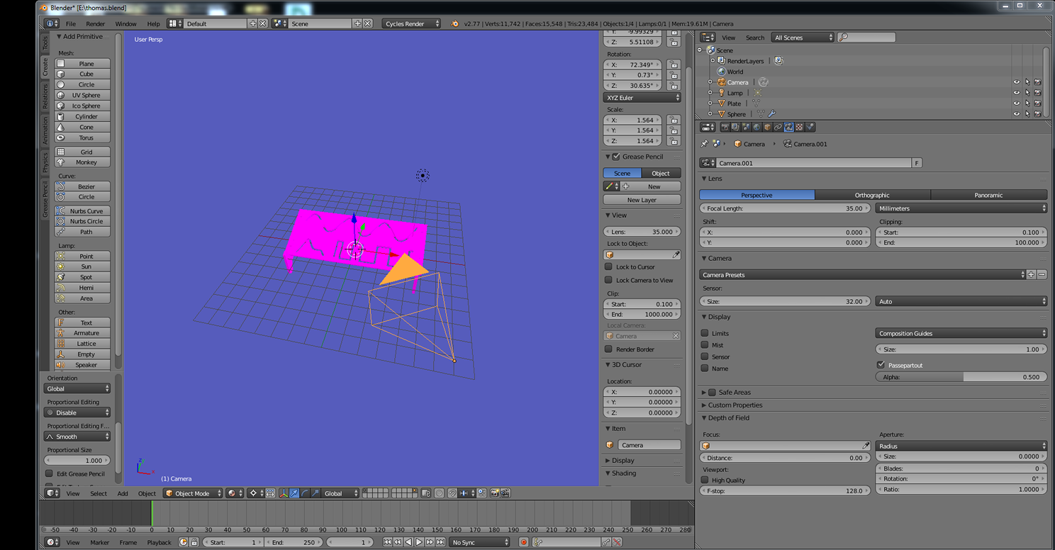
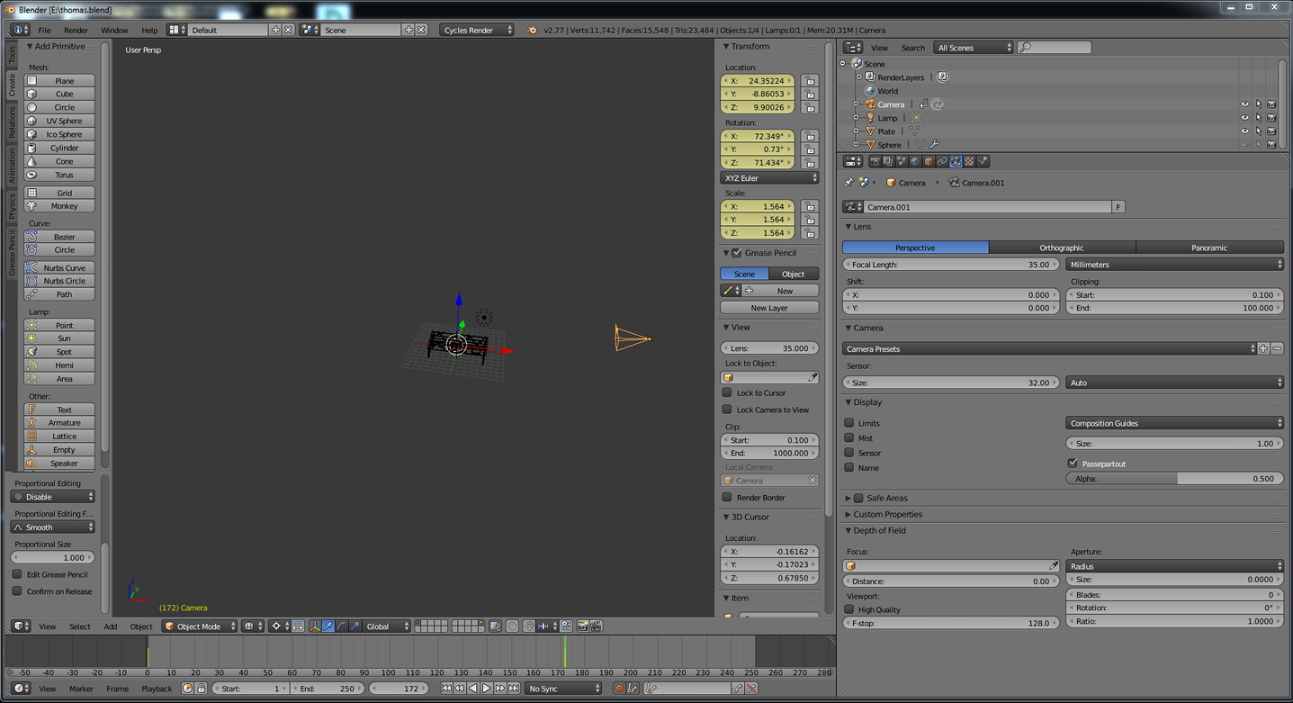
When a 3D scene shall be rendered, you need to distinguish between world coordinates, the individual object's coordinates and the camera locations. Blender lets you select all of them freely.
I put my scene into a sphere, the camera at a 45 degree angle from the ground, and assigned a color to the sphere.
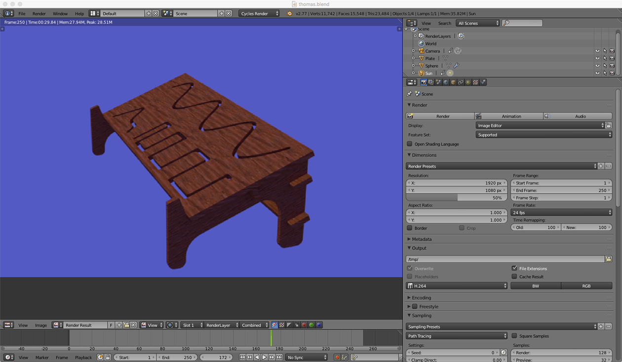
Then I rendered an image of the scene with default parameters. Blender renders an image tile by tile.
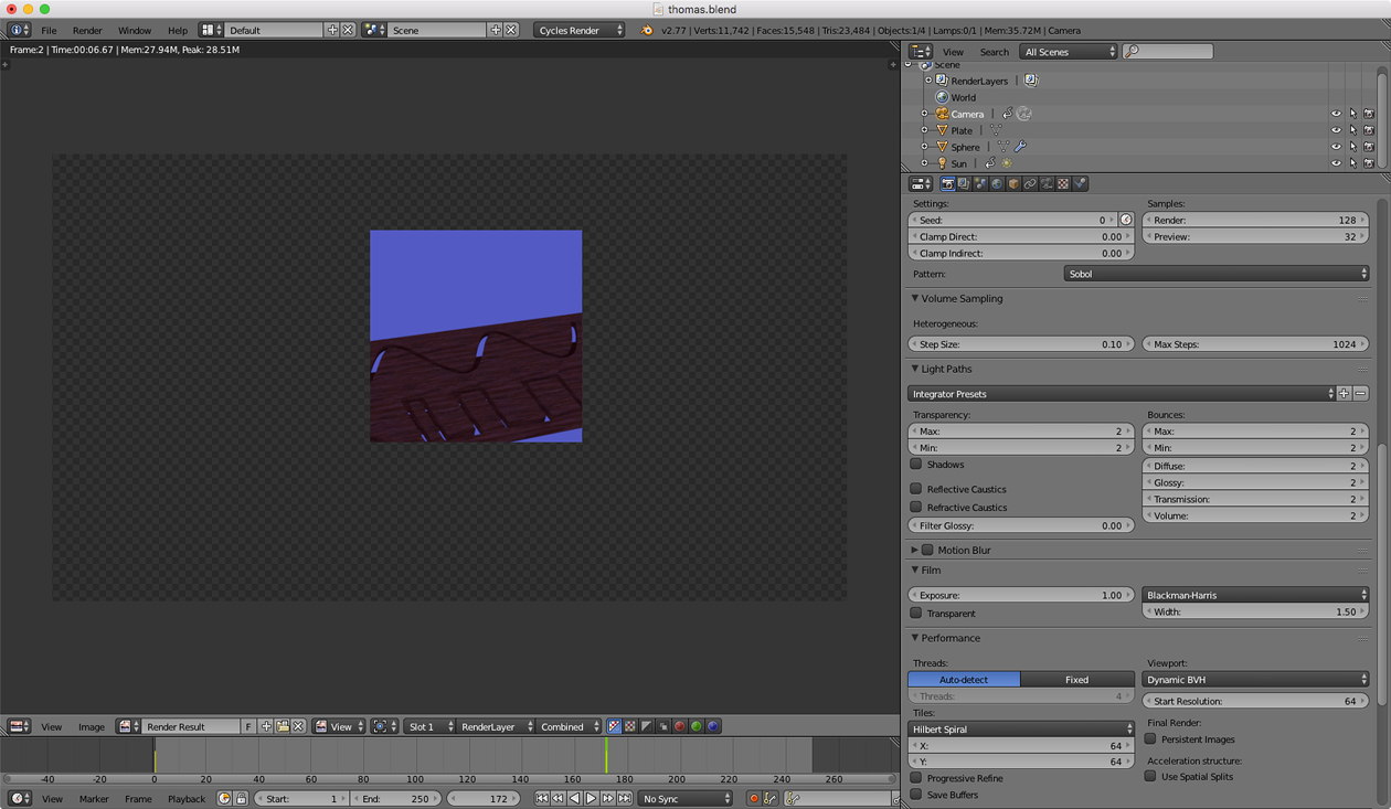
The finished image looked like this:
I made a small animation, for which the camera would briefly "fly around" the synth stand. As the animation is computed frame by frame, it has taken roughly 40 minutes. The result is below.
Lessons learned
- I learned how to use Fusion 360
- I improved my skills using GIMP
- I now know the basics of Inkscape
- I learned the basics of 3D rendering with Blender
- OpenOffice and MS PowerPoint are not evil in general.
Source files
GIMP
Old project - Base Unit Front: here
LEDmePlay flyer huge GIMP project: here
LEDmePlay flyer motif only: here
LEDmePLay Screenshots: here
LEDmePLay Screenshots on a grid: here
LEDmePlay Joystick and Device: original shot: here
Inkscape
Final project Systems Diagram: here
Fusion 360
Design for a Waldorf Blofeld Keyboard synthesizer stand: here
Same design spread on the ground with dog bones: here
DXF file with dog bones: here
Blender
Blender scene with my synth stand. In Blender, please execute "Render/renderImage" in order to see the scene: here
Bodies for my synth stand exported as STL in ZIP file: here