FabAcademy Final Project
Description
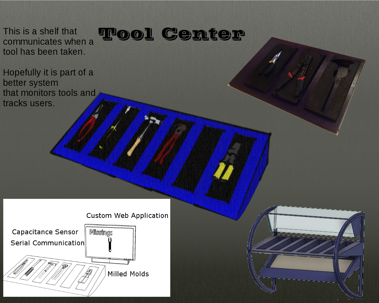
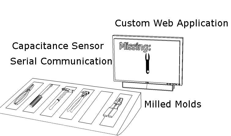
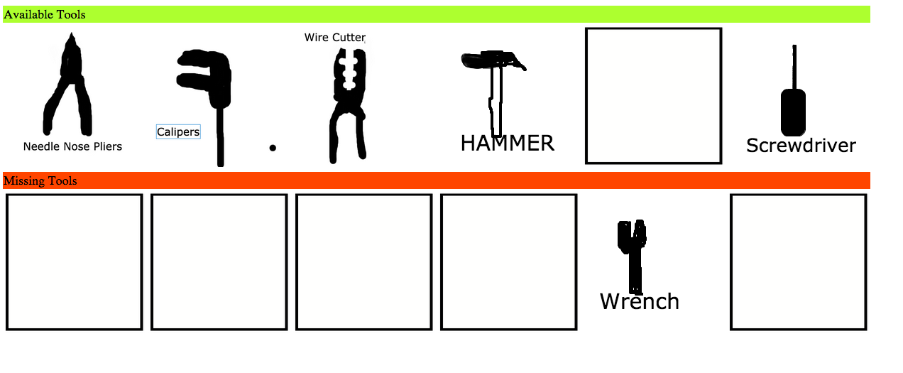
The project is a shelf that knows when a tool is missing. It should send a message
to a webpage that shows which tools are missing.
 Video
Video
The Skills
I modeled my design using Fusion 360 and Sketchup for artistic work.
I used Pixlr for Raster Graphics
I used CorelDraw and Inkscape for Vector graphics.
I wanted to focus on a single shelf especially the electronics and interfacing those electronics with the computer. Hopefully in future, I can expand functionality and scale.
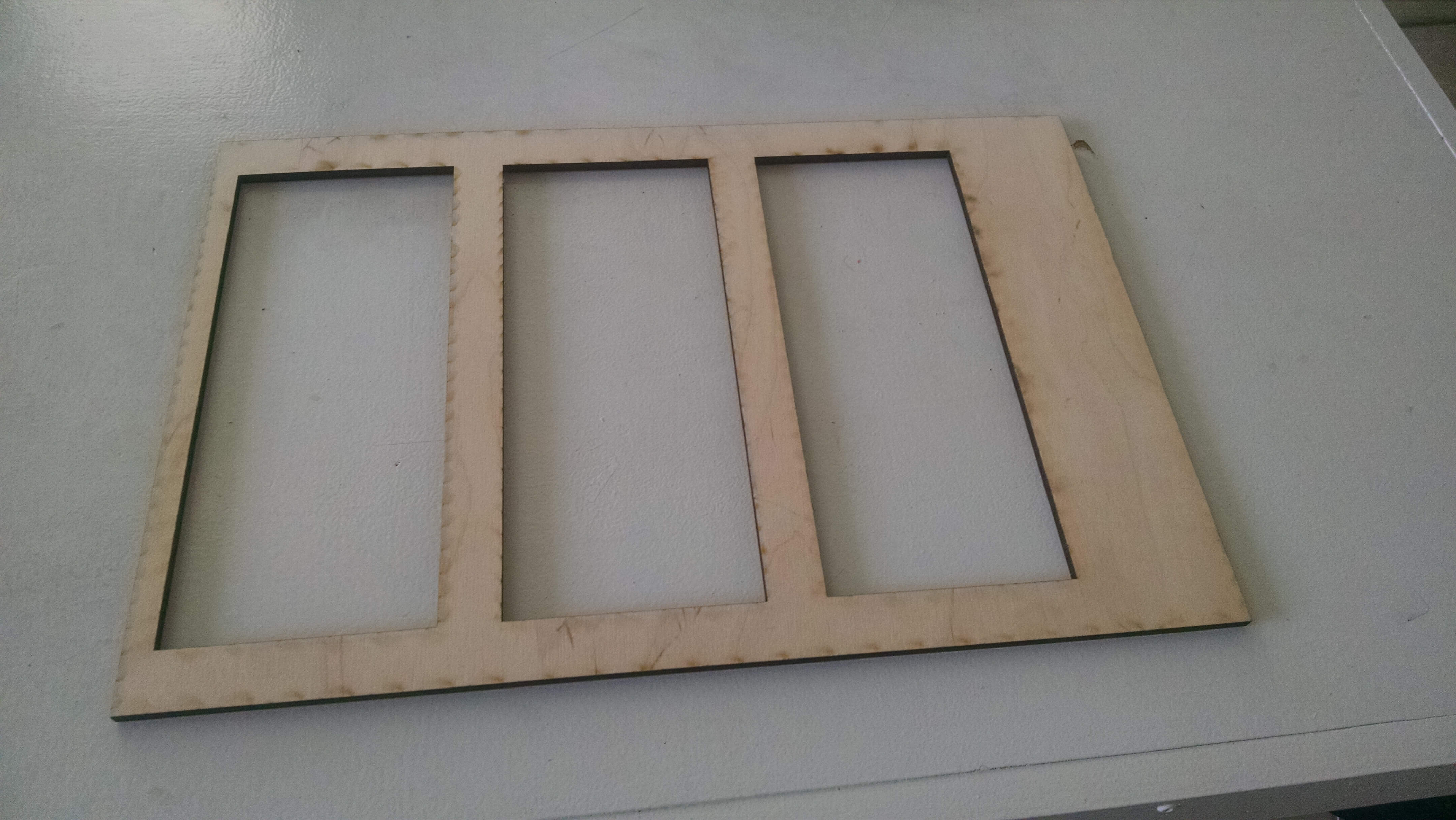
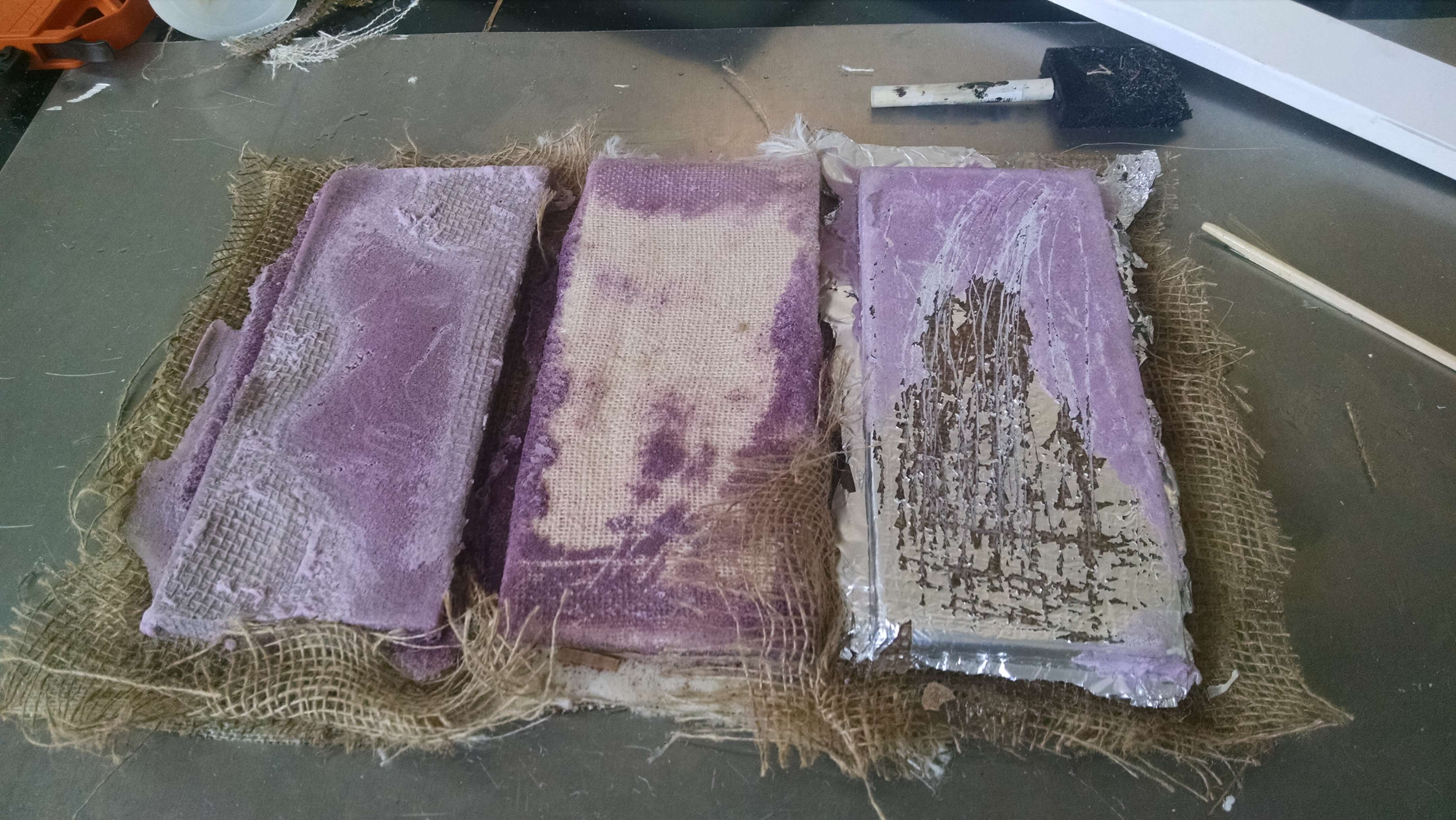
I used the laser cutter to cut a mockup wood shelf that I was going to use for testing. However, the mockup, looked better than the composite shelf. So I just started using the wood shelf.
I laser cut a case for one of the PCB boards.
I laser cut burlap pieces for building the shelf(which I did not like.)
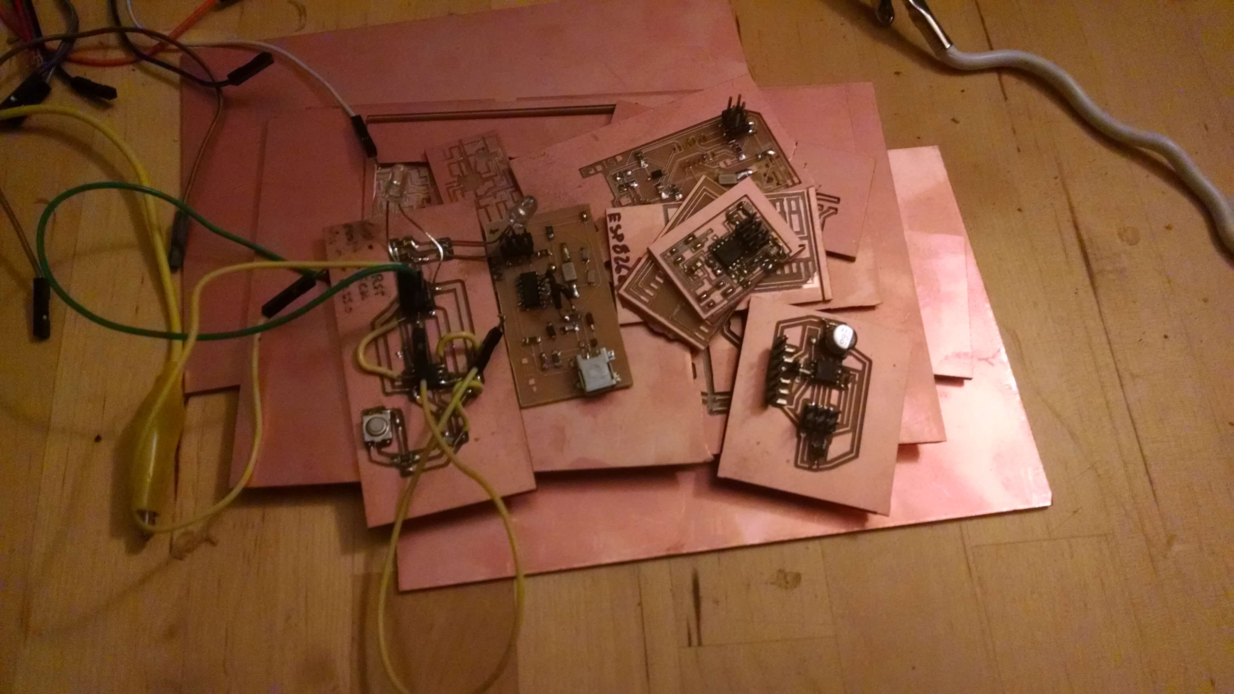
I designed a board using a raster graphic program.
I planned out future boards for LEDs and RFID using Eagle.
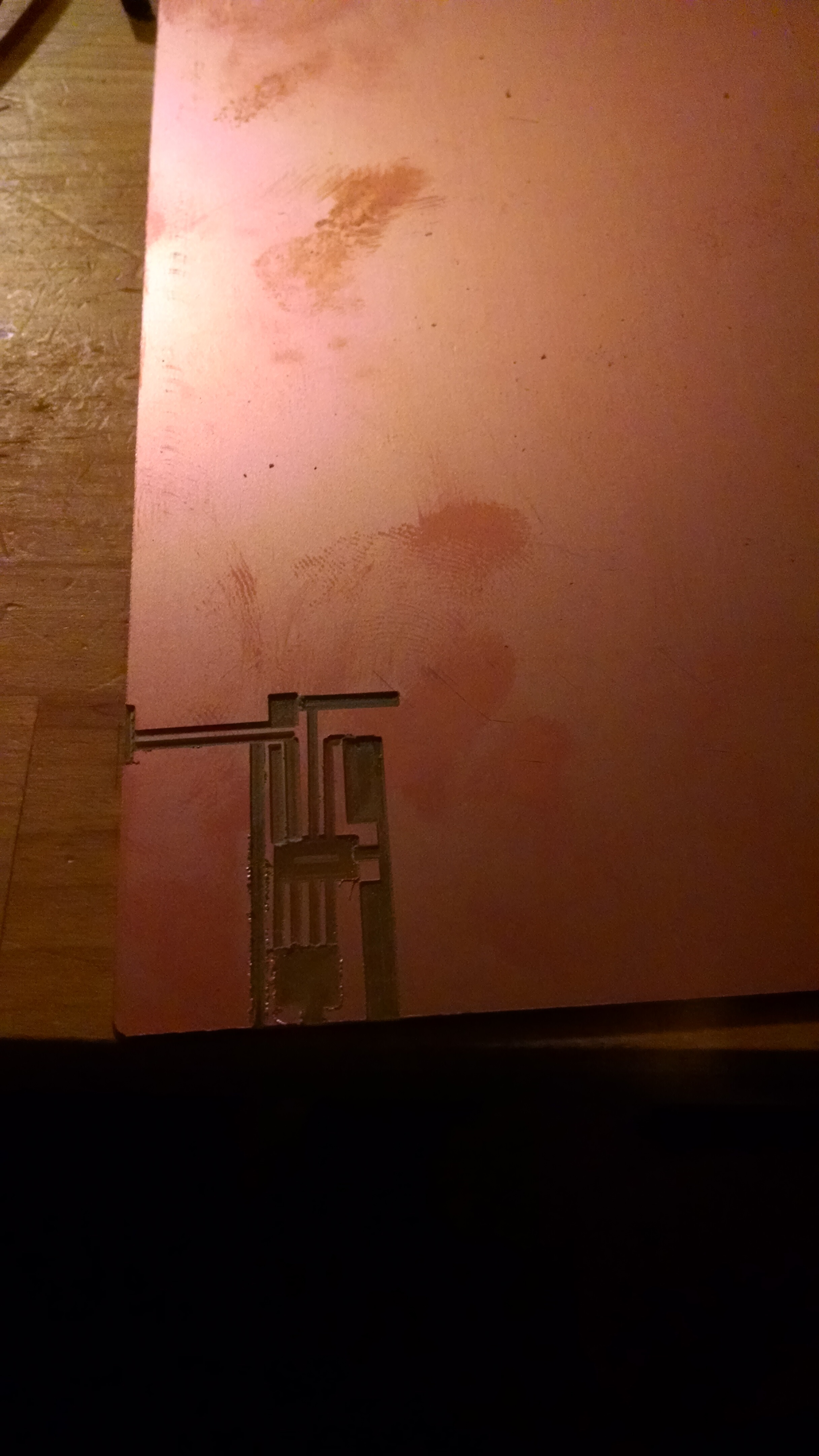
The board is made using a Carvey
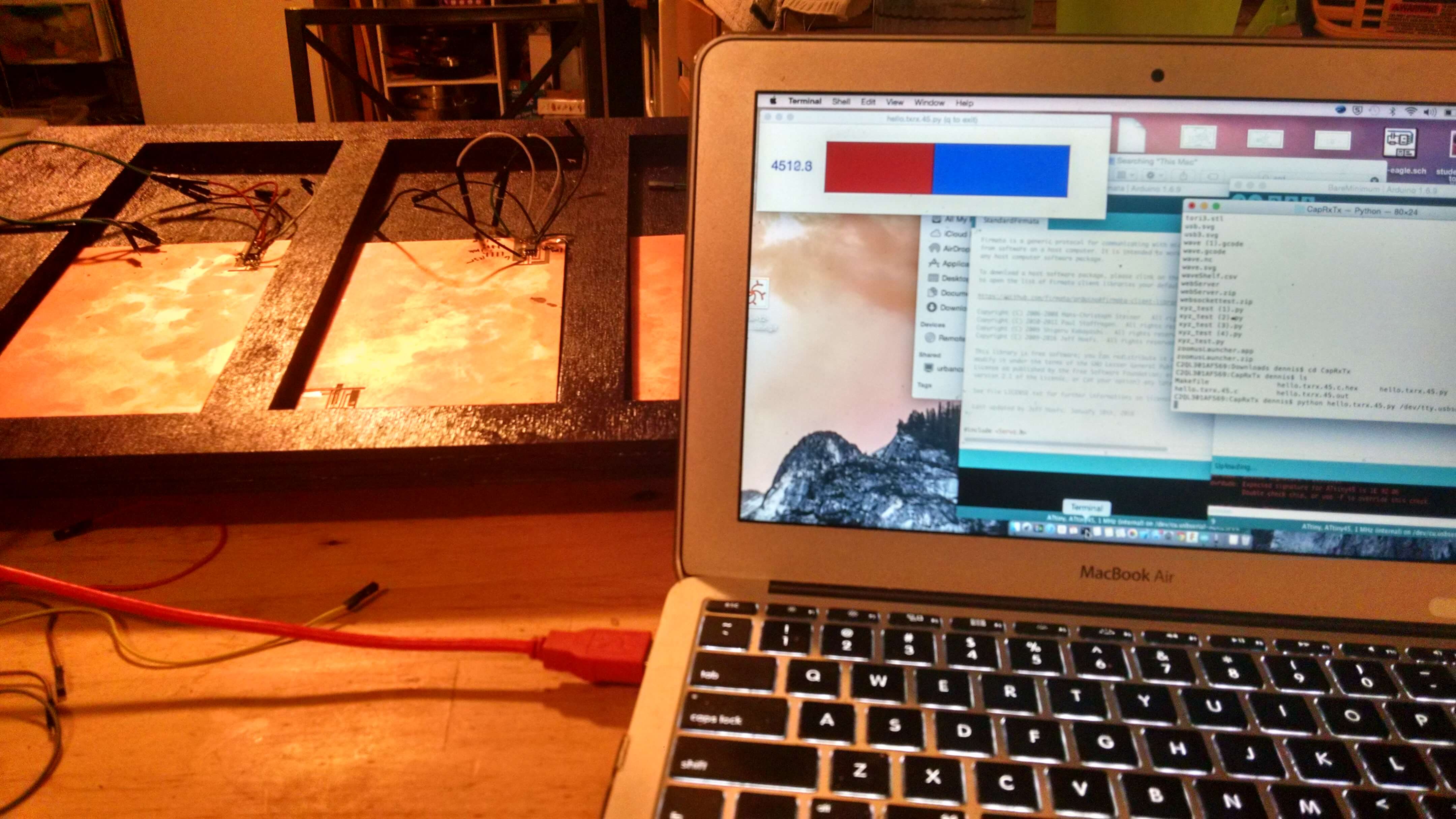
I programmed Attiny45 to read capacitance and relay the signal to a second board(Arduino Uno/Arduino Mega). That board is connected to a computer via FTDI cable.
I have built the TX/RX step response example and modified the board for my use.
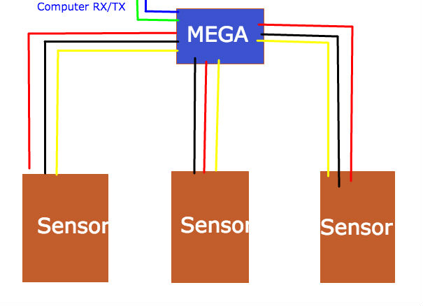
I have a simple serial connection between the sensors and an additional microcontroller that is connected to a computer.

I designed my own app. It used Node.js to communicate with the microcontroller. It used javascript to display the info.
In my second iteration, I adapted the python program that came with the RXTX application.
The Process
I had three major areas to work on. To keep the project moving, I worked on these three
areas in parallel.
Machining, Milling, & Molding
Goals
Plan
The shelf is constructed out of burlap/resin composite. The technique is wet layup with compression. In order to make the tool trays, I am modling the composite around a XPS foam mold. The mold is made using the CNC Mill(Carvey).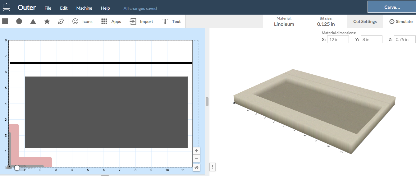
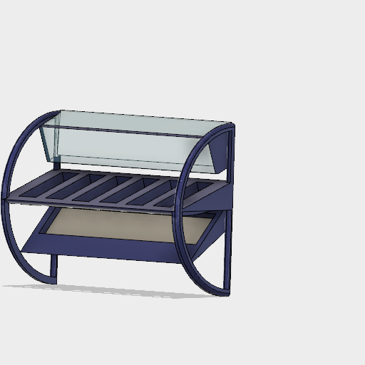
I ended up modelling the original plans in Fusion 360. I did not need a 3d structure
since I was going to make molds using the CNC mill and laser cutter. I modelled a wood
structure that originally was going to be a mockup using CorelDraw. I used Easel to model
the pieces(3) for the CNC mill.
Casting and Molding
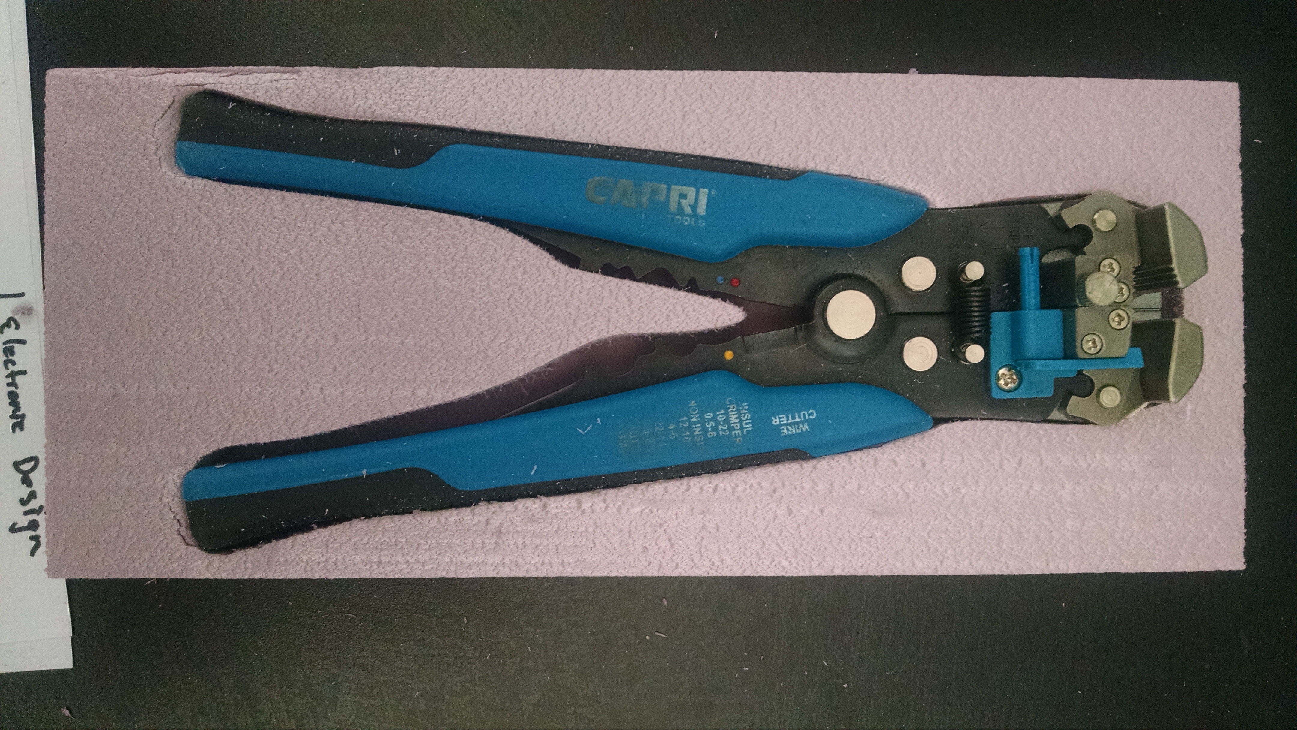
Each indentation of the shelf holds a tray. The tray is made by casting the outline of a tool so that each tool has a specific location.
To make the trays, a photograph of the tool was taken. The outline of the tool was made using the spline tool in CorelDraw. The image was saved in a SVG. The SVG was used to generate the gCode using Easel(However, this could be done with FabModules as well.)
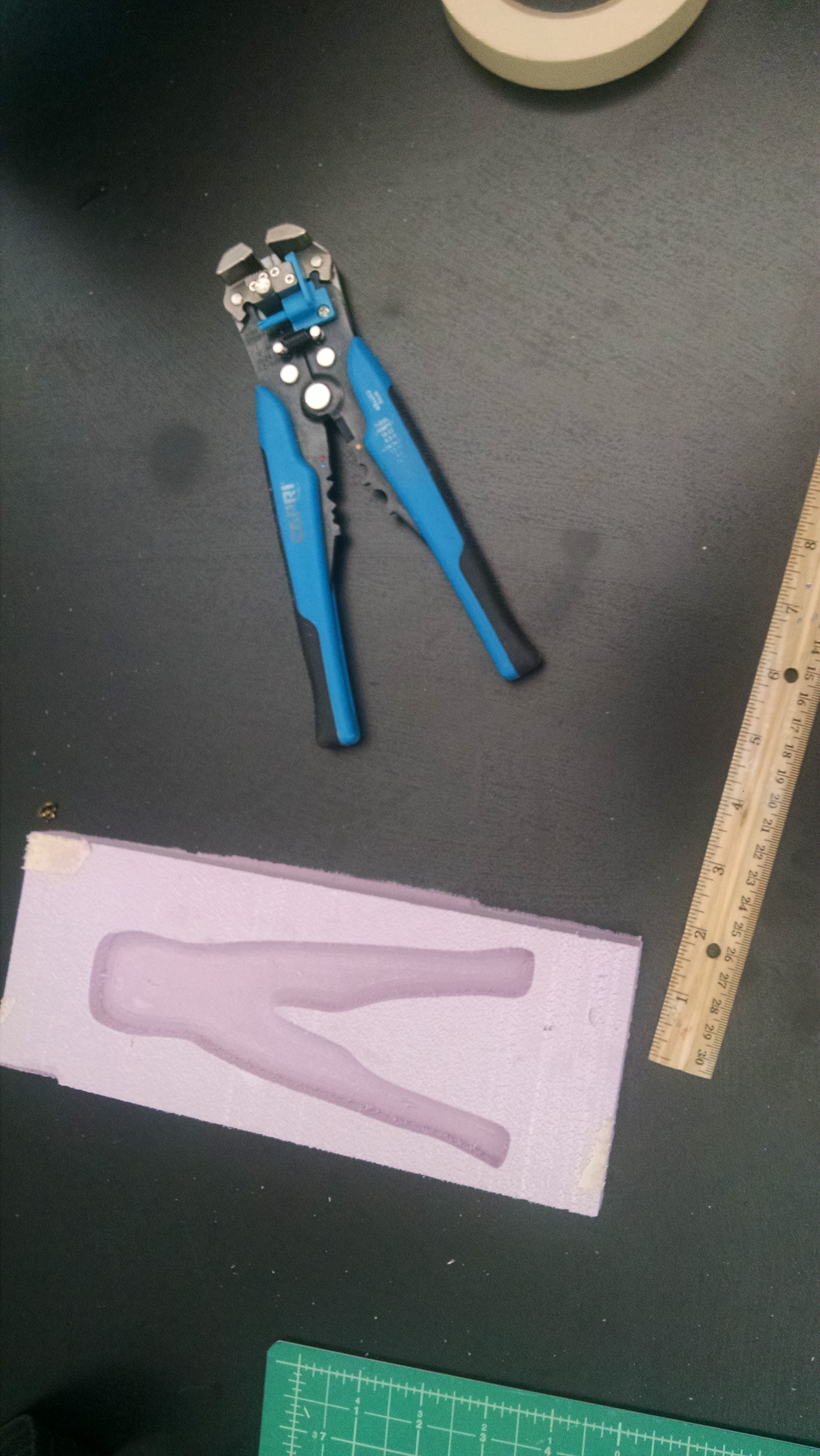
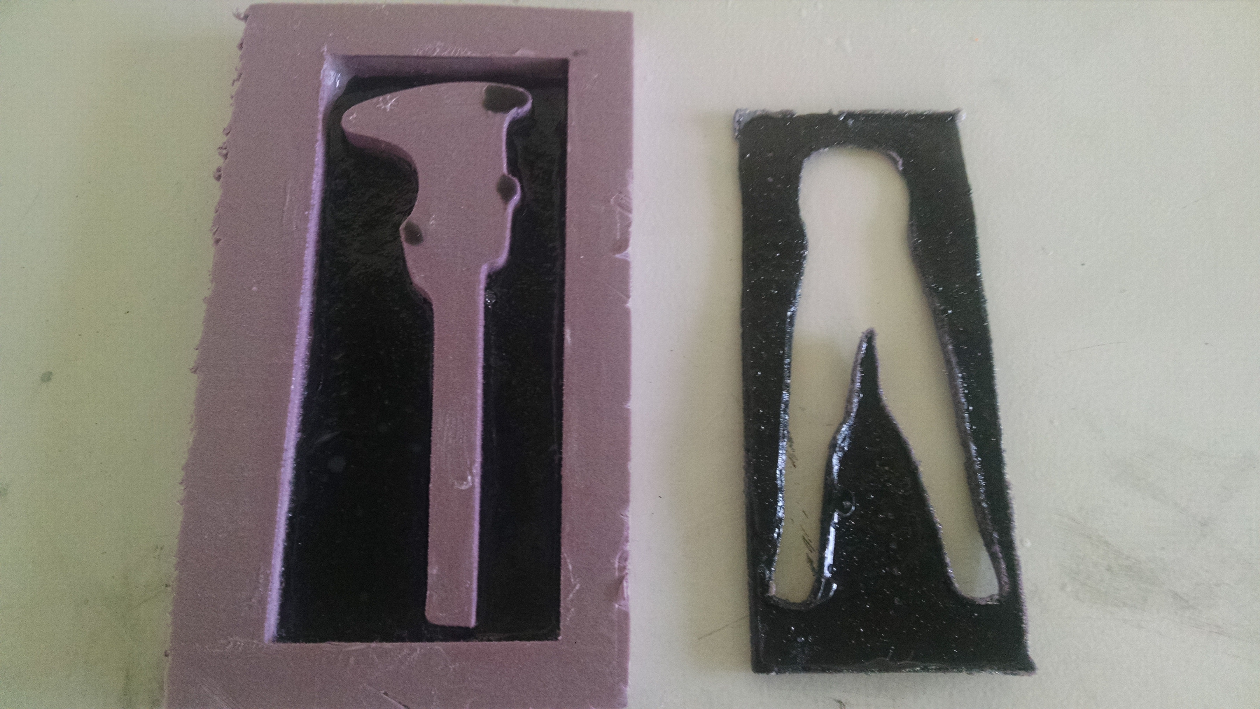
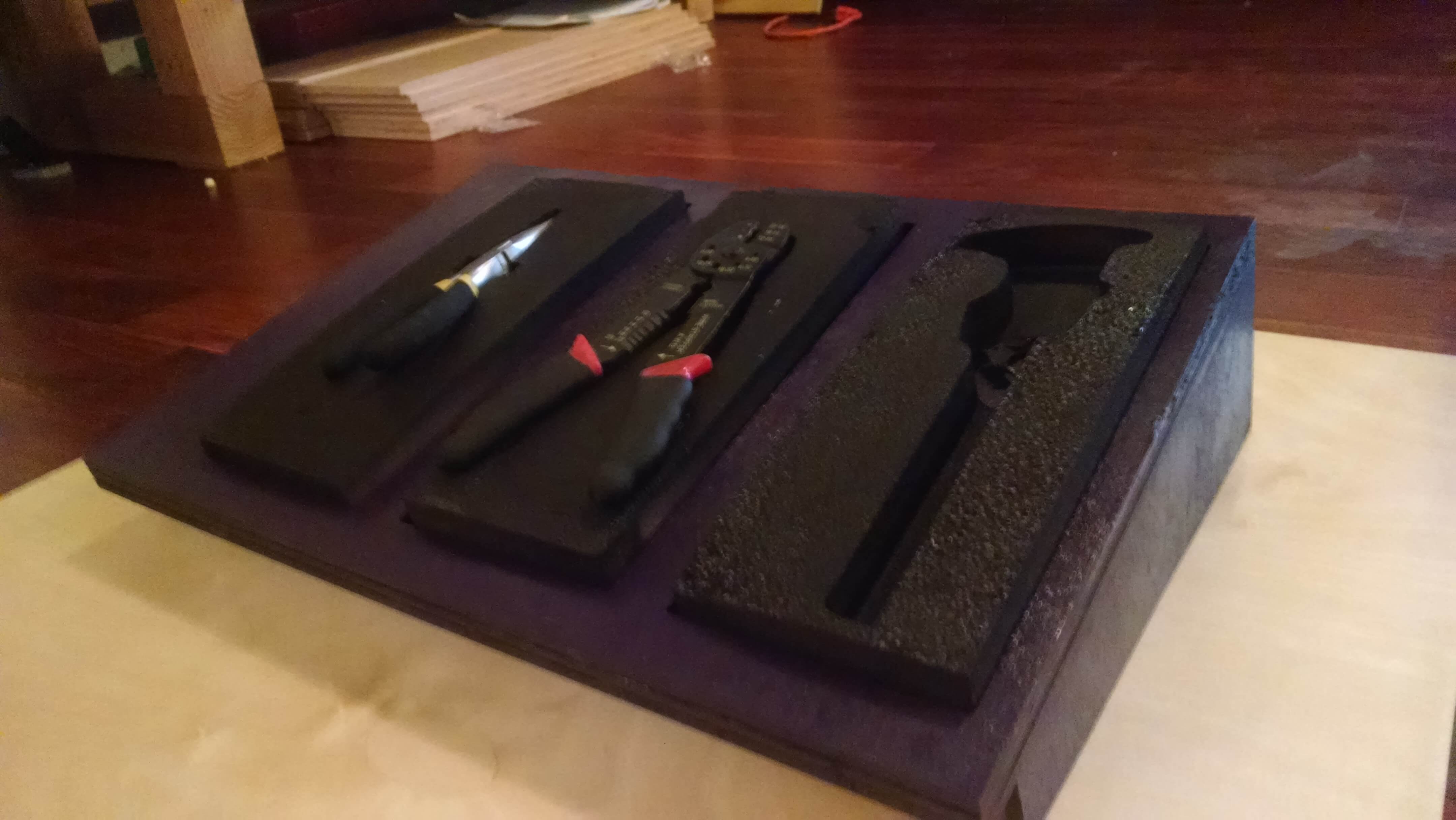
I decided I like the styrofoam molds better. I milled both postive and negtive molds for the tools.
Instead of pouring money into finding a better casting plastic, I want to laser cut tool foam some time in the future. After taking the time to build molds for casting and composite building, I prefered wood and foam. Originally, I built the wood and foam to do testing while I made molds and prepped the structure.
Here is the "final" structure:
Electronics(Circuitry & Programming)
Goals
Plan
- Build a rfid system(transmitter on each tool and reader at tool hub.
- Add some led indicators.
Process
Building the capacitive sensor....
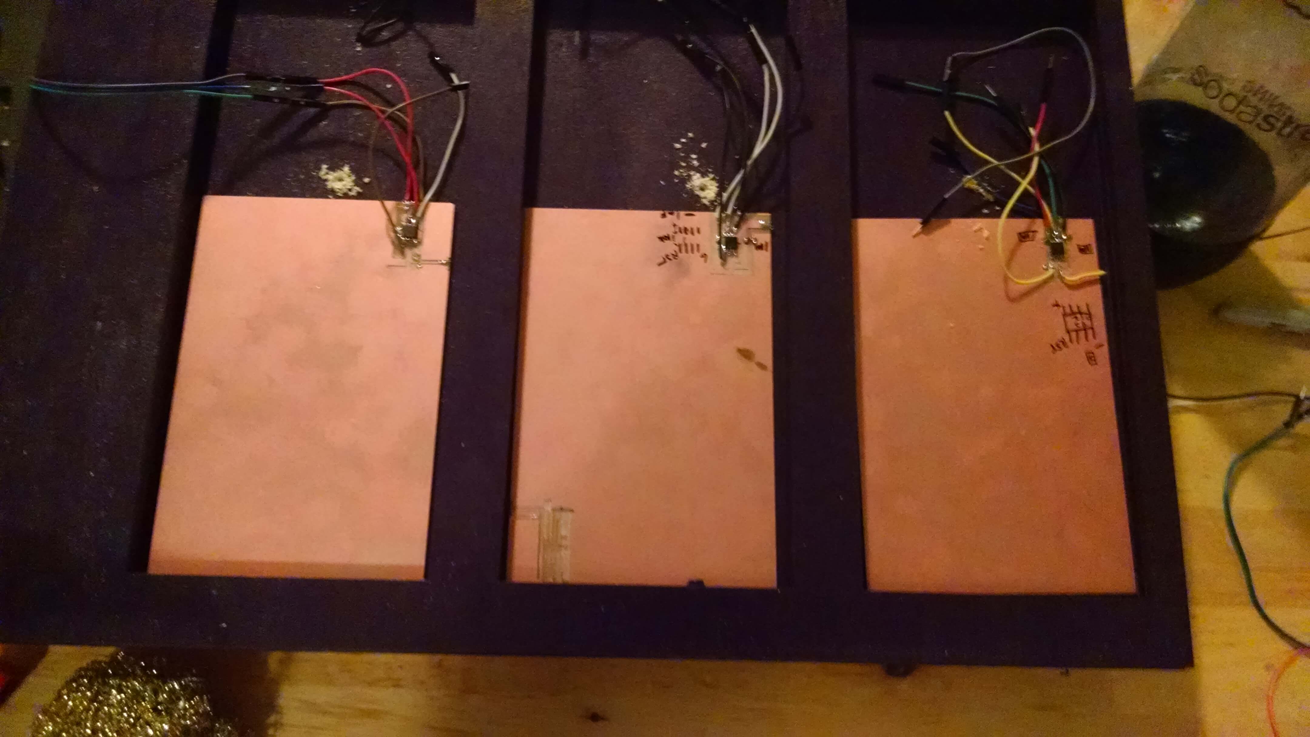
I want the sensors to lay under the tools. This means I want to build the board without any header pins. This worked out, but in hindsight, I would design my circuit with header pins and de-solder the header pins after programming.
The sensor was hand drawn using Pixlr. The image was then shrunk so that the chip size matched the Attiny45.
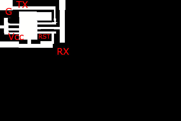
 Soldering
A 1M resistor was soldered between RX and Ground and RX and VCC.
A 1uF capacitor was soldered between VCC and Ground.
A jumper wire was wired to the back side of the Double PCB from the TX.
In order to program the board, I soldered wires onto each of the programming Pins.
At this point, the location of the pins is easy by memory, but for reference:
Soldering
A 1M resistor was soldered between RX and Ground and RX and VCC.
A 1uF capacitor was soldered between VCC and Ground.
A jumper wire was wired to the back side of the Double PCB from the TX.
In order to program the board, I soldered wires onto each of the programming Pins.
At this point, the location of the pins is easy by memory, but for reference:
Pin 1 --> RST
Pin 2--> Not needed for programming
Pin 3 --> Not needed for programming
Pin 4 --> Ground
Pin 5 --> MOSI
Pin 6 --> MISO
Pin 7 --> SCK
Pin 8 --> VCC
Programming:
Arduino has an example to program the sensor:
I used the Capacitance Sensor Example sketch with only modification of the pins.
I used pins PB3 and PB4 as RX/TX.
CapacitiveSensor cs_4_2 = CapacitiveSensor(4,2);
becomes:
CapacitiveSensor cs_4_3 = CapacitiveSensor(4,3);
Only one sensor is needed because I choose to use microcontrollers on
each sensor as opposed to one Attiny45 for 3 sensors.
                    CapacitiveSensor   cs_4_3 = CapacitiveSensor(4,3);

                    void setup(){
                       cs_4_3.set_CS_AutocaL_Millis(0xFFFFFFFF);
                       Serial.begin(9600);}

                    void loop(){
                        long total1 =  cs_4_e.capacitiveSensor(30);
                         Serial.print(total1);
                         delay(10);
                     }
The example gives a nice readout. However, there is a lag in the time, in which a tool is moved.
Redesigning
After presenting my project(Jun 20), Neil suggested using the Capacitance Sensor in his example. This would solve two of my problems. I needed to ground my tools(physical contact) and I needed to acquire samples over about 10 seconds to account for noise.My board was the same. Not suprising since I had looked at Neil's example and the example on the Arduino site before building my sensor.
The only thing that need to be done was a change in code.
I am still struggle with understanding Neil's Example Code. I will work on that. There are many references to the board that I have not learned and am struggling to grasp. However, the functionality of the code was the same, and my pins are the same as well.
I just have to pay attention to his ouput.(more on this in interfacing)
Interface Building
Goals
Stretch Goals
Process
I investigated several ways to implement this process(Getting the microcontroller(s) to talk to a web client.) I have node.js and websocket installed from previous work and examples.I choose to use Firmata, because I can program through the Arduino IDE.
Firmata is a protocol for a microcontroller to talk to a computer. This will allow me to write a custom webpage that is getting info from the microcontroller. Update: many hours were wasted on that one point. I did not realize that most of the time when I npm install, it provides only local. That is easy to see from the placement of the folder node_modules, but at the time ......These packages need to be installed in each project or globally.
To understand how to use Firmata, I found this tutorial helpful: OpenChapters. The example found in the Arduino IDE: StandardFirmata can be uploaded to the board.
This gives a webpage access to the input and outputs of the board.
You can use many different applications to talk to the microcontroller, but I want to focus on javascript/HTML5. Here are the Client Libraries that can be used to find examples. This allows us to receive the Analog Data from the microcontroller.
That signal can be processed to determine whether or not a tool is in its holder.
A display can be developed to show the status of all tools. In my first iteration of the project, I stuggled with websocket. To get around this, I had node.js save the data from the microcontroller:
Javascript File
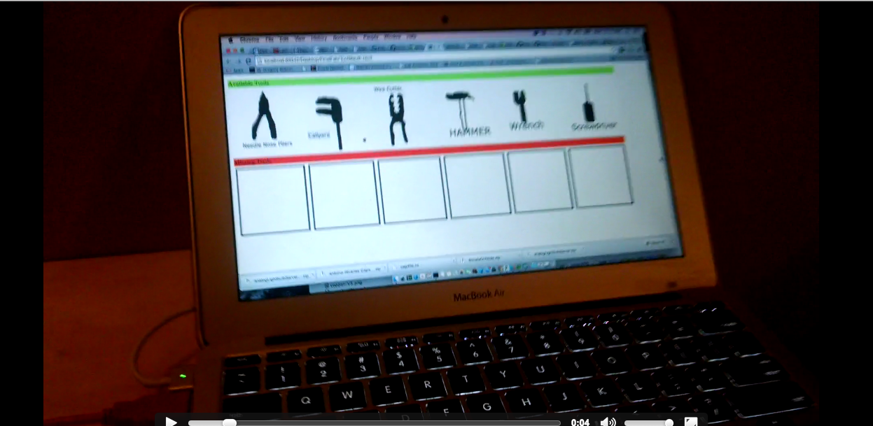
Here is the HTML5/JS WebApp:
Tool Sleuth
The app worked fine. But.... It was not elegant enough for me.
Reboot....
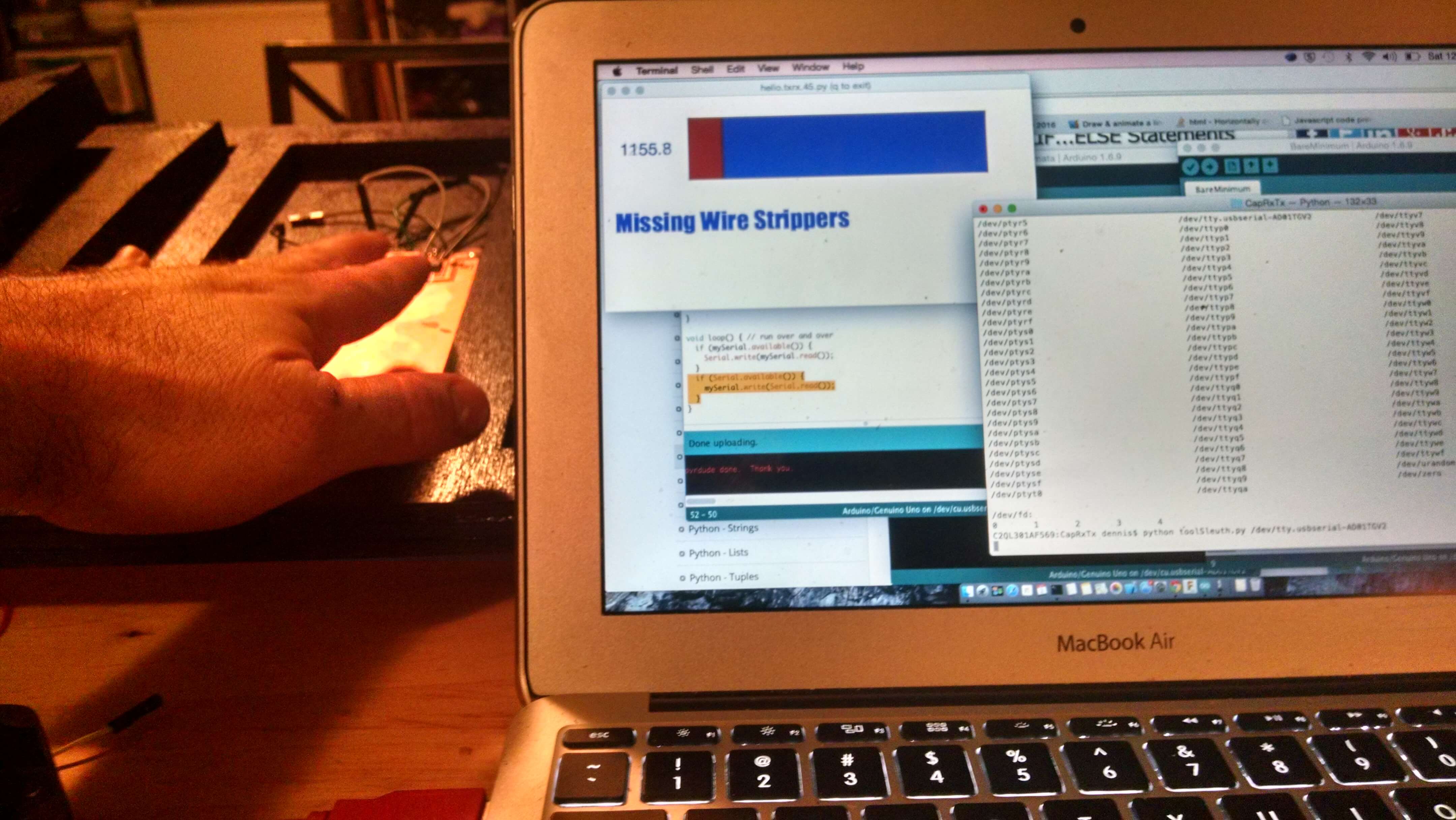
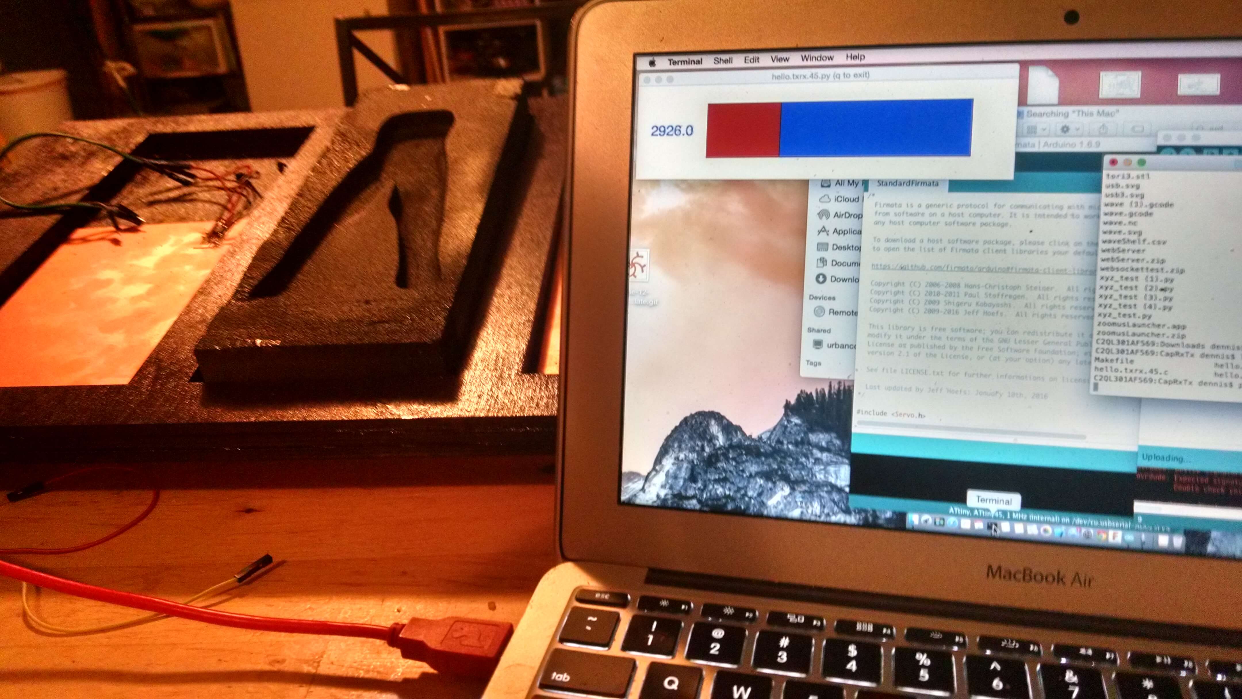
After the presentation of my project, Neil suggested looking at his sensor. When I did this, I also adapted his code to write a python based interface. It is an OK stop gap to getting the project working.
I used the python code from Neil's RX/TX: Python Code found in the week on Input Devices.
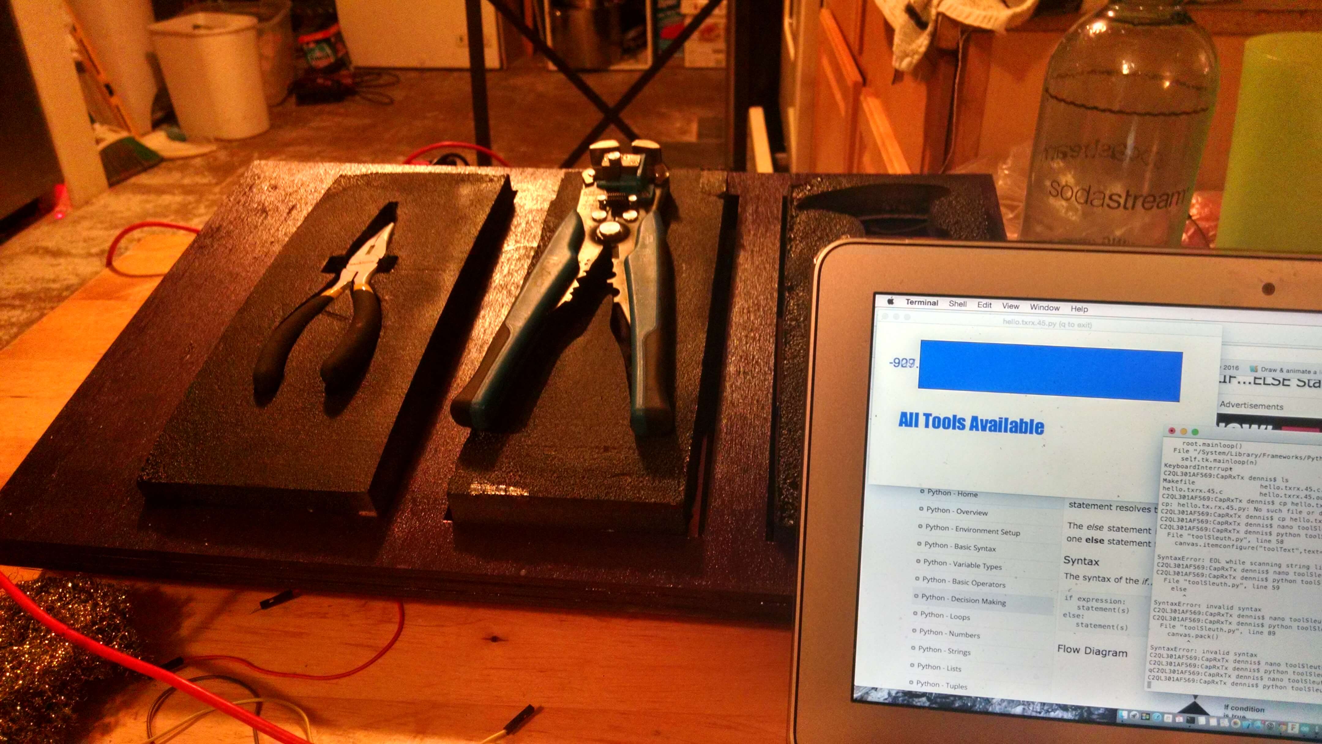
Here is the readout when all tools are available: