Week 13 Programming Attiny board to show in LCD
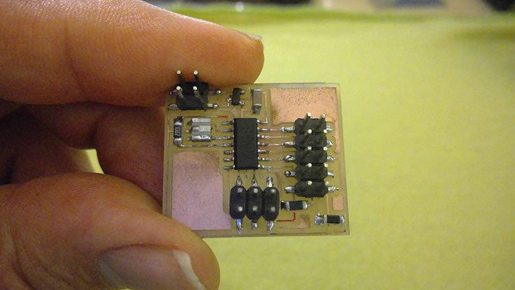
Making the Attiny LCD board
You need the following materials:
- AtTiny44a
- A resistor of 1k Ω
- A resistor of 10k Ω
- A resistor of 100k Ω
- A 5v regulator
- A capacitor of 1uF
- A 20MHz resonator
- Headers
- An LCD
The circuit to build is
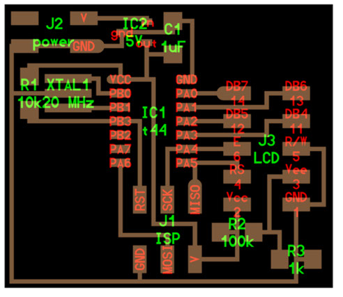
I followed the diagram for solder the components and place them on the board.
Connecting the LCD-Attiny board
Download the files ".make" and ".hex" of the page for the LCD from http://academy.cba.mit.edu/classes/output_devices/index.html
For the programming of the LCD write as super user on the console the following:
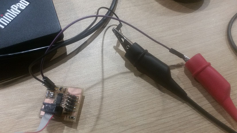
sudo make -f hello.array.44.make program-avrisp2
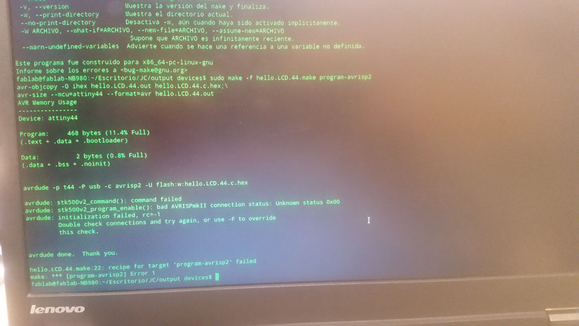
The chip couldn't be programmed. I prefer to continue with the option of Fabduino connecting to a LCD, this is what my final project would use. Because, this Attiny board shows only what is programmed on Attiny 44, so It will not be usefull for my final project.
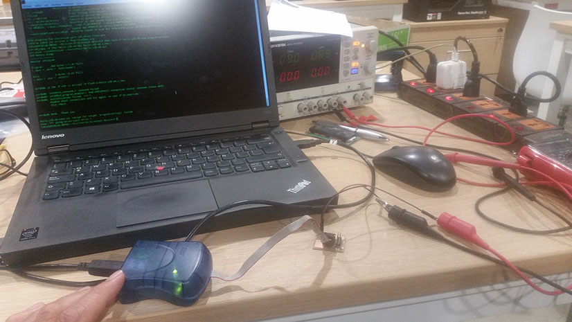
UPDATE: Making again the board
In the previous experiment, I suspected about a bad soldering. So I built another one, and solder the parts, programm, and finally see it working.
You can see it in the video: