Network communications?
This week we have to create a network between processors, the point is to have "nodes" that can interact with each other so we can make them to things as a group, but just talking to one of them.
So I decided to start with the first exemple on Neil's page : the asynchronus serial communication.
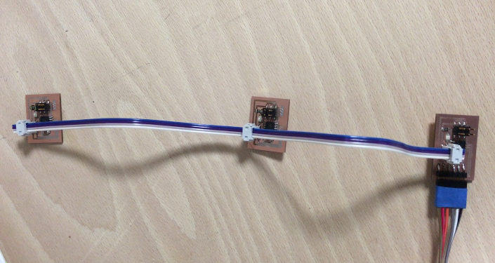
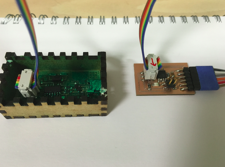
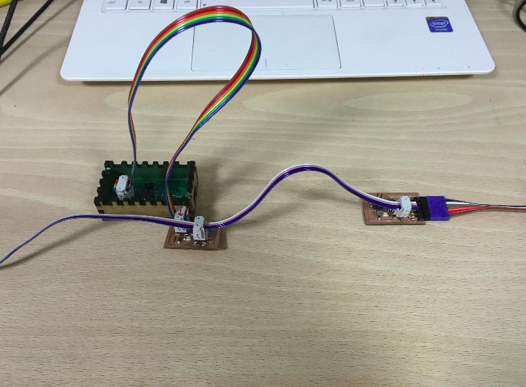
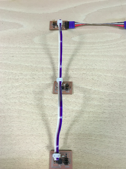
It consists in one bridge that controls nodes, in my case two; each node has a red led as output signal that will allow us to see what is going on (we'll also use the serial monitor).
The program we'll upload to the boards should allow us to control inividualy each node just by talking to the bridge (its just a node with FTDI pins), so by sending a command in a serial monitor I will control each led.
So if I want to light the last node, the command has to pass true the first two nodes! I think that is a beautifull exemple of physics in action! What a complex path for those electrons that finaly get converted in light at the end of their journey! All that in a couple of micro-seconds! I wonder how much time exactly, if I have time I will plug an osciloscope on that last node and measure the time taken by he signal to arrive.
In the mean time I need to advance on my assignment!
The board
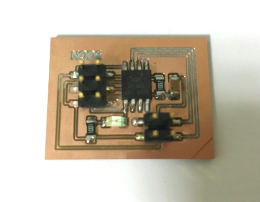
Milling
The node: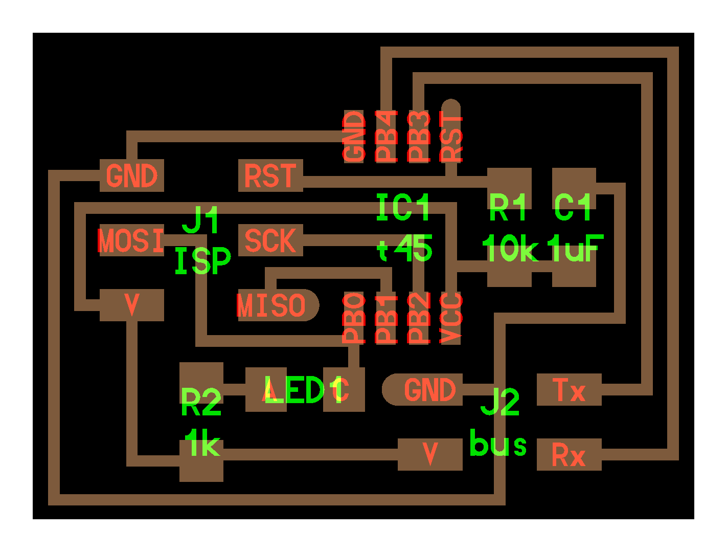 The bridge:
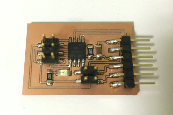

Soldering
After all the boards we've made this became a routine!
Only difference with the node is the FTDI pins which will allow us to talk to the boards
 Settings:
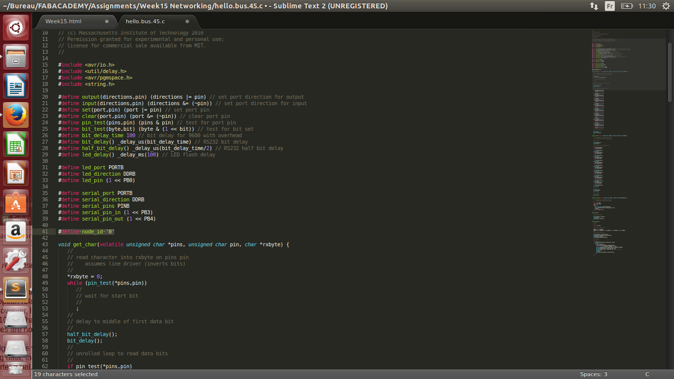
Programming
Settings:Since I have already been flashing micro-chips I have everything I need on my computer to talk to my boards (GCC, AVRDUDE...).
I just need to download the ".c" and .make" files from Neil's page :
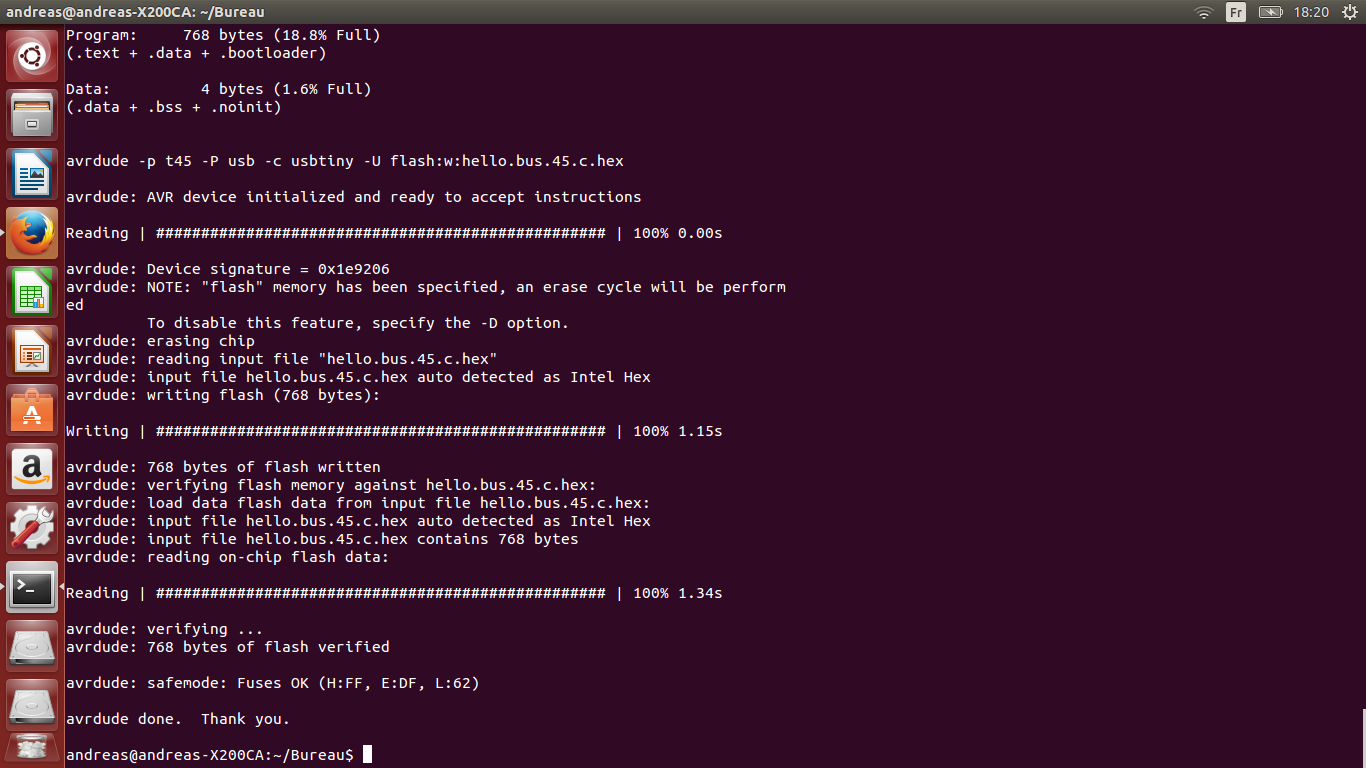
This is the procedure:
This is the result :
You also should see that this command created two files :"hello.bus.45.c.hex" and "hello.bus.45.out".
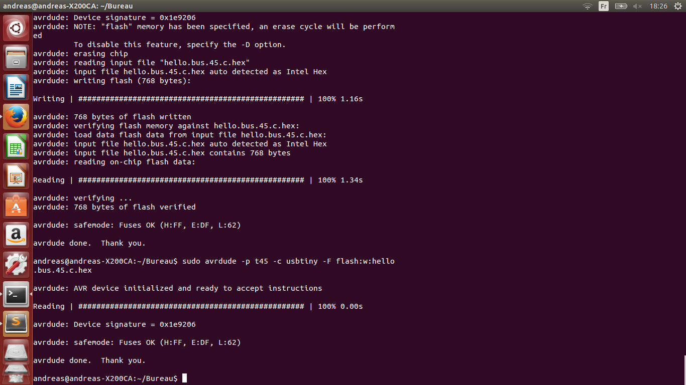
And last command, flashing:"sudo avrdude -p t45 -c usbtiny -U flash:w:hello.bus.45.c.hex"
Now I can flash the node : "sudo make -f hello.bus.45.make program-usbtiny""
Once the process is repeated for the second node, the network is ready to recieve our commands.
Communication
Arduino IDE
I was able to talk to my boards using the Arduino IDE, I simply connected all my network and used the FTDI cable to connect the bridge to the computer.
Just needed to select the port : "/dev/ttyUSB0", and open the serial monitor (keep the baudrate at 9600).
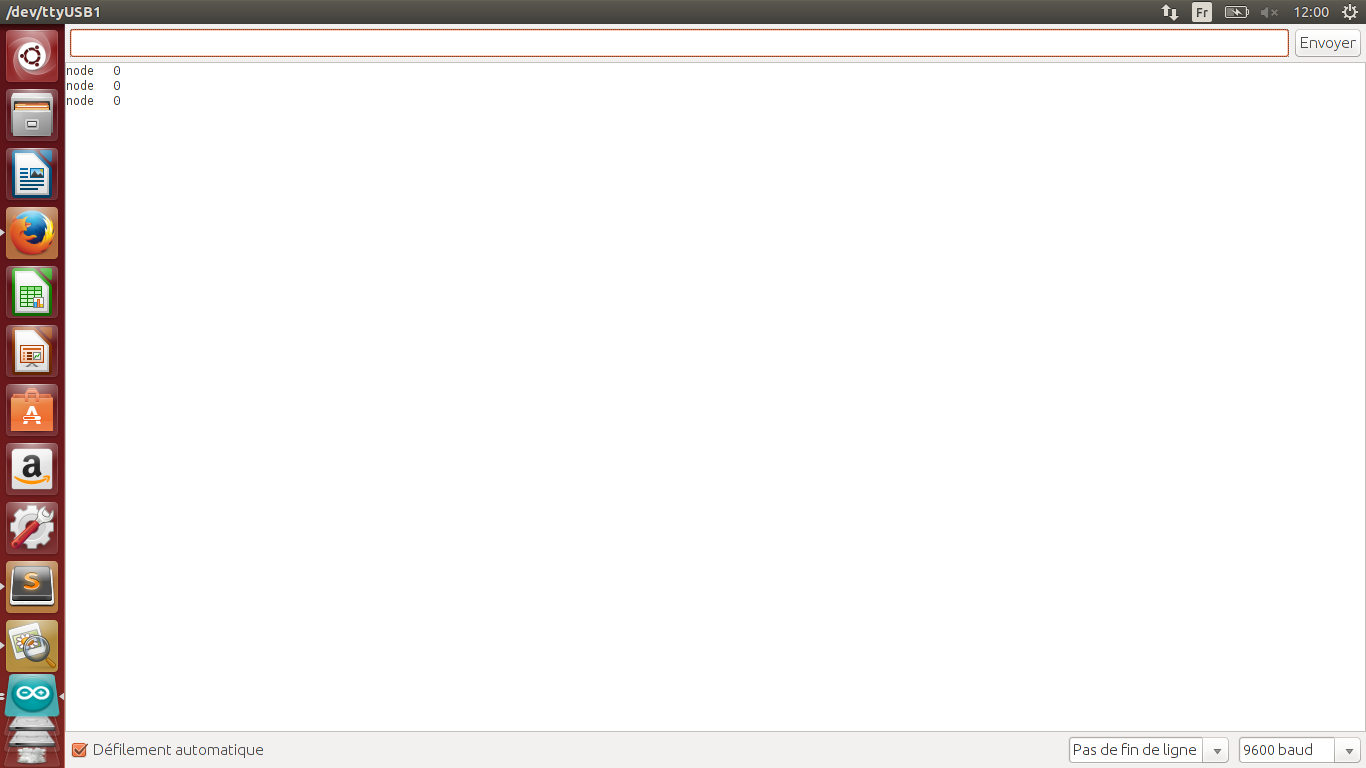
Typing any key on the monitor made all the nods blink at the same time and I could see on my FTDI cable a led blink, so comunicattion was established, but there was a problem because I couldn't talk individualy to a specific node.
Here is a short video to show the result:
Python
So I decided to try to do something on my terminal because Arduino made things kind of work but I couldn't realy understand what was going on.
So as I did for my INPUT assignment, I looked for a graphical interface in Python from which I could talk to my network by serial communication.
And I found this : term.py
Simply download this file and put it in your working directory where you have your ".c" and ".make" files (you need to have python on your computer, check my week 11)
Connect your boards as before, and open a terminal in your working directory, type: "sudo python term.py /dev/ttyUSB0 9600 "
So term.py is the graphical interface, /dev/USB0 is the serial port and 9600 is the baudrate.
You should obtain this :
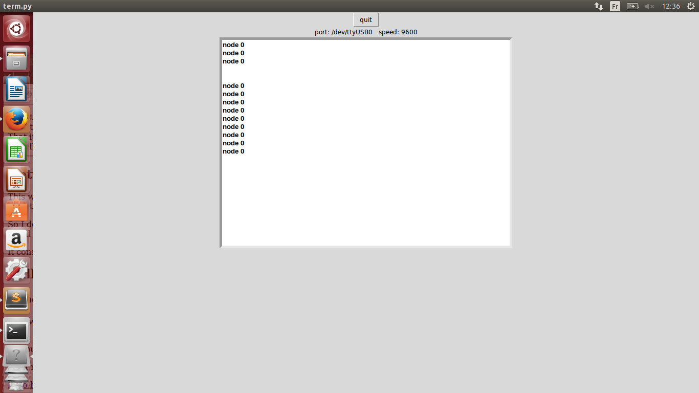
Typing "0" should make the bridge blink, "1" the first node etc.
Demo in video:
So I managed to flash all my boards using the terminal, and communicate with them with the Arduino IDE (not totally clear but a link was made) and perfectly with the Python Gui of Neil.