This week in electronics....
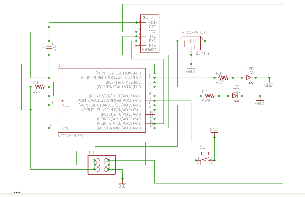
We are taking our introductive skills of creating circuit boards and redesigning/recreating another design of a board as well as adding parts to it. In the past, I have had some experiences with a few design tools in this arena.... mainly Eagle CAD as well as experimented with the pcb.cad file in fab modules. I believe I will go along with Eagle for the sake of time and once my board is complete, I will "get my feet wet" and experiment with other programs that I have not tried. This go round, using Eagle was not that much of a challenge. Although, I've had some experience and am slightly familiar with the program, I felt like I needed a quick refresher. So I went on youtube and found a very heplful tutorial on the design basics of Eagle. From this tutorial, I decided that for my board, I am going to added two LEDs and Resistors with my button. What I want it to do, I'm not so sure about yet.

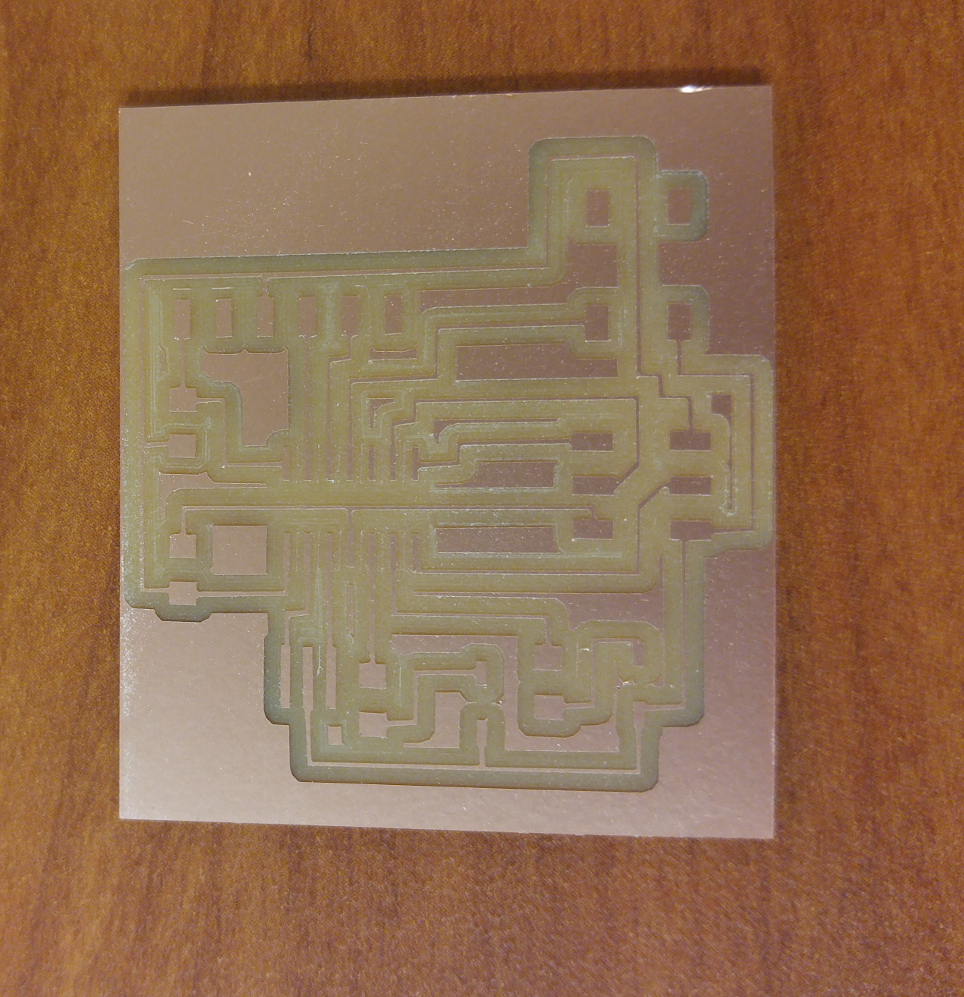
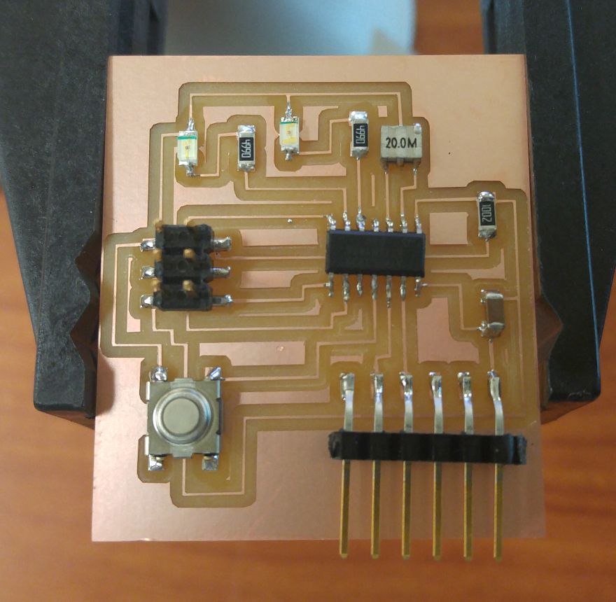
Once my board was milled and cut out, I realized I had an issue. It was not one that would effect the board drastically, but moving forward if i decided to create my own board I will keep this next step in mind. Neil spoke on it during the lecture, and one thing that I did not do was before milling traces to offset my board to -1 so that it can clear any excess copper.
Slight change in plans...
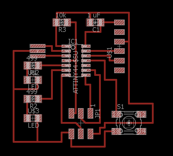
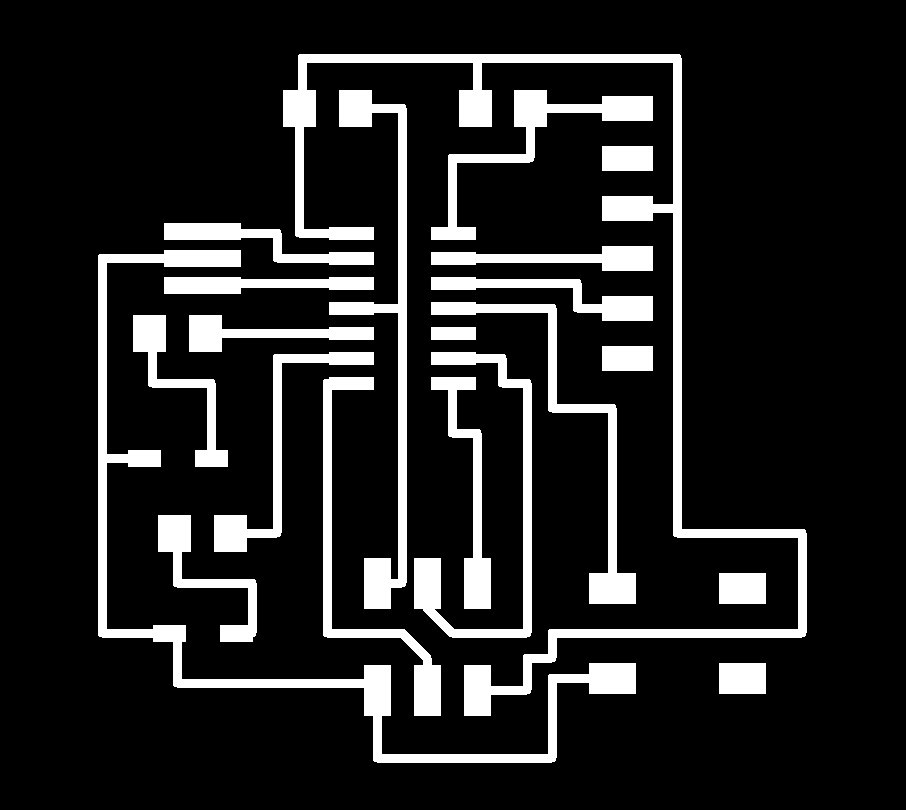
After having our local review, I found a few issues with my board which makes me say YES I did encounter a few issues this week, not all were trivial and I did learn something from this experience. I discovered that when I decided to recreate my board in Eagle, I should have made sure that my width of traces were larger than what the default settings were. Another complication was figuring out what size resistors I would use. In doing calculations with slight confusion in some moments, I realized as the weeks go on I will need more practice in calculating and finding resistance. Lastly, during the review, it was pointed out to me that although my Switch is connected to GND, it could use an external pull-up resistor so that once the board is on, readings would be more precise and accurate. Therefore, I will make sure that during Embedded Programming week the internal pull-up resistor will be on.