
2016
Rudrapalsinh Solanki
Final Presentation:
3D Printing
3D Printing
3D Printing
3D Printing
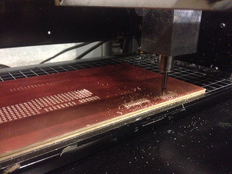
Milling
Laser Cutting
Laser Cutting
Laser Cutting
Electronic Design
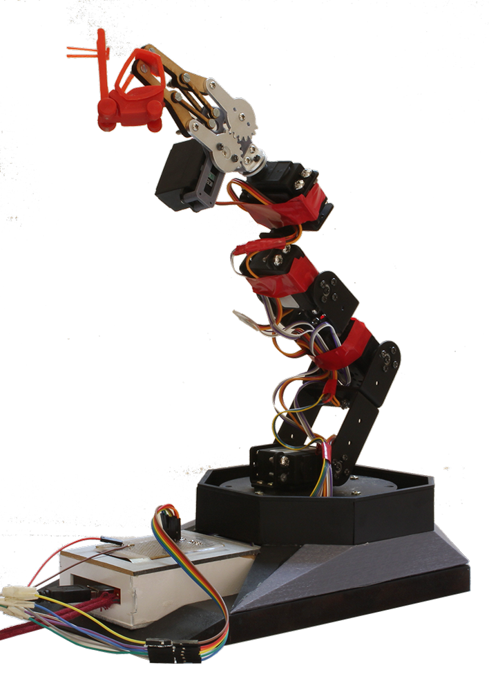
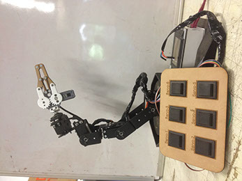
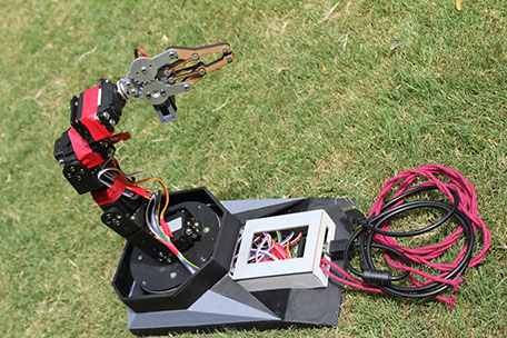
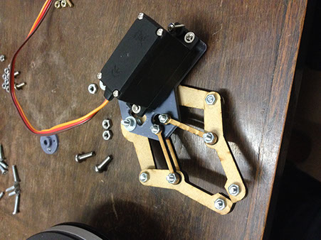
SUPER ARM AFTER CLEANING UP AND SETTING UP THE WIRES

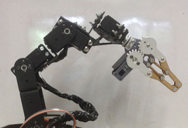
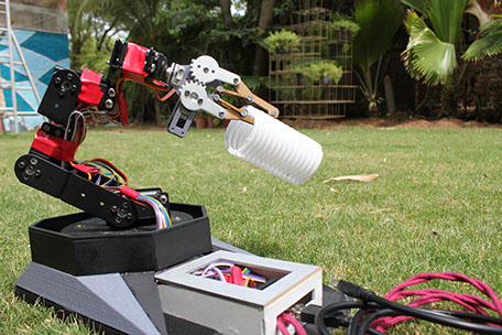

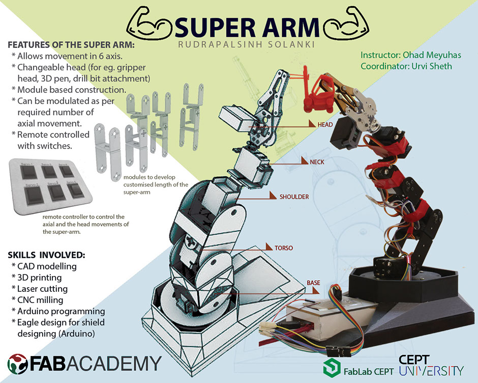
Super arm is a robotic arm that works mechanically. Super arm works/moves like a human arm. The super arm will be able to move in all 6 axis and also moves in X/Y plane on the surface. The arm will be fixed on the deployable table base.
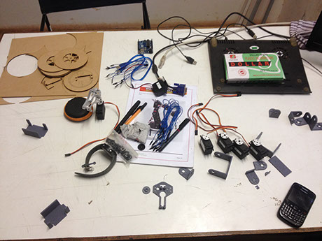
Tools/techniques to be used for making super arm:
1. 3D Printing
2. Milling (CNC)
3. Casting
4. Electronics
5. Sensors
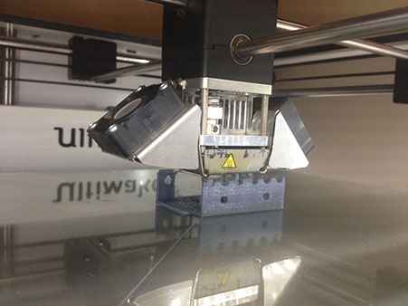
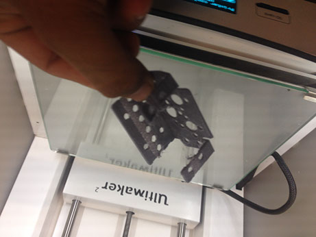
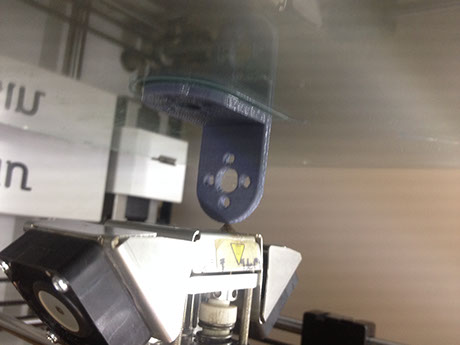
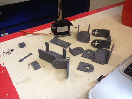
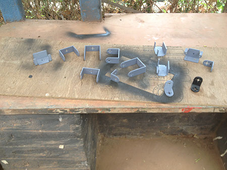
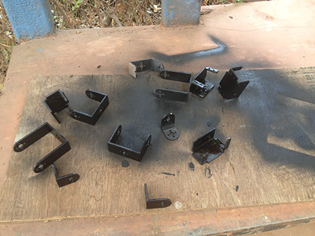
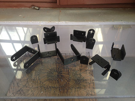
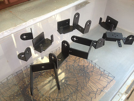
1. 3D Printing : All the components are 3D printed. First they are designed in the rhino and the modules are joined to each other and checked if the movement of the arm works. Once the movement is confirmed then the components are 3D printed and then colored black to make it look alike all motors.


.jpg)
.jpg)
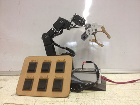
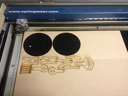
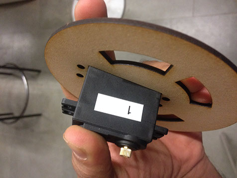
2. Laser cutting :The Base is made up of MDF 3 mm and 18 mm. The drawing of the base is in rhino and then taken it to the laser cutting and the files are laser cutter .
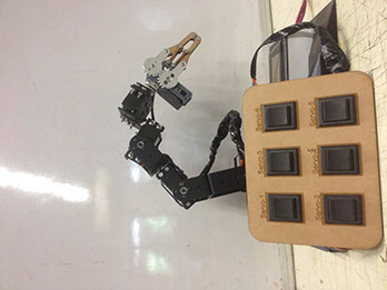
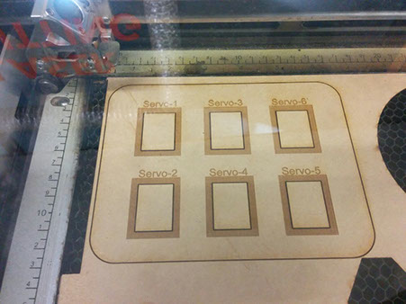
Second task that i did was to make the remote with the laser cutting technique that includes the cutting technique and also includes the raster process in the mdf to name the control units.


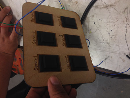
3. Electronics : For the electronics I am using the arduino uno/ mega board for the connection of the 6 servo motors. I am yet working on the code for making the each switch controlling the motor.

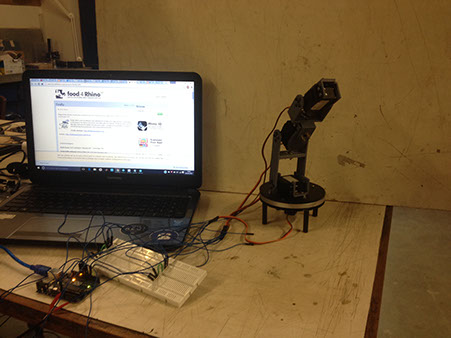

Blue tooth Connection to control the arm. There was a huge failure in terms of the movement of the arm rotating. Due to the connection of the servo motors through the mobile blue tooth, there were a lot jerks that the arm was having. It was not moving in the smooth movement.
Blue tooth Connection that i tried was an open source connecting system. Now again I switched back to the basic model that I was thinking. I started making the remote that can actually control the arm in all the 6 axis.
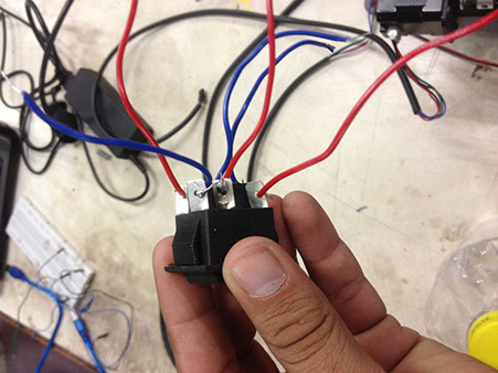
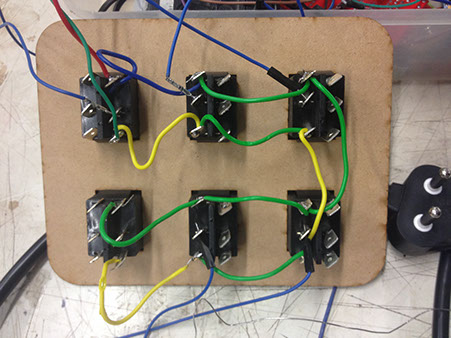
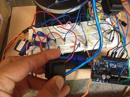

The first trial that it worked for the first axis that was the gripper rotation with the switch. There was an issue that the switch had 3 connection pins so in total there i needed 12/15 pins to connect in the arduino board. So then I decided to make the shield for arduino and custamize it according to my requirement.

4. Sensors: I usedGY-61 ADXL335 Triple Axis Accelerometer / Analog Sensor for Arduino - Blue EDC-308704 for my initial test for working with the accelerometer. Providing the voltage output of signal disposal, it can measure +/- 3g magnetic field full-scale acceleration minimum. It can measure skew detection of the application of static gravity acceleration, and sports, impact or vibration acceleration in dynamic. The remote can also be replaced with the dynamic gloves that can control the arm.
Final Project Files