This week our assignment was to add a sensor to a board and take measurements. Since I am working on a final project that needs to "sense" rocks, I thought I'd figure out an input device for this challenge. I was inspired by sitting at a stop light and considering the coil sensors that were placed in the concrete under the car. Those are appparently called "inductive loops," and they consist of a coiled wire to form a loop as part of a resonant circuit. The proximity of metal or conductive objects in that coil changes the resonance. I figured this would work as long as the rocks that I was sensing would be metal. (See my moulding and casting project to see how I made "metal rocks!")
Next I had to stuff the board. I was finding it difficult to determine which capacitors I could use, so I did a little research and I found a super-handy conversion chart, so that I could understand nF vs uF vs pF. Here is a link to that great chart that I referenced often.
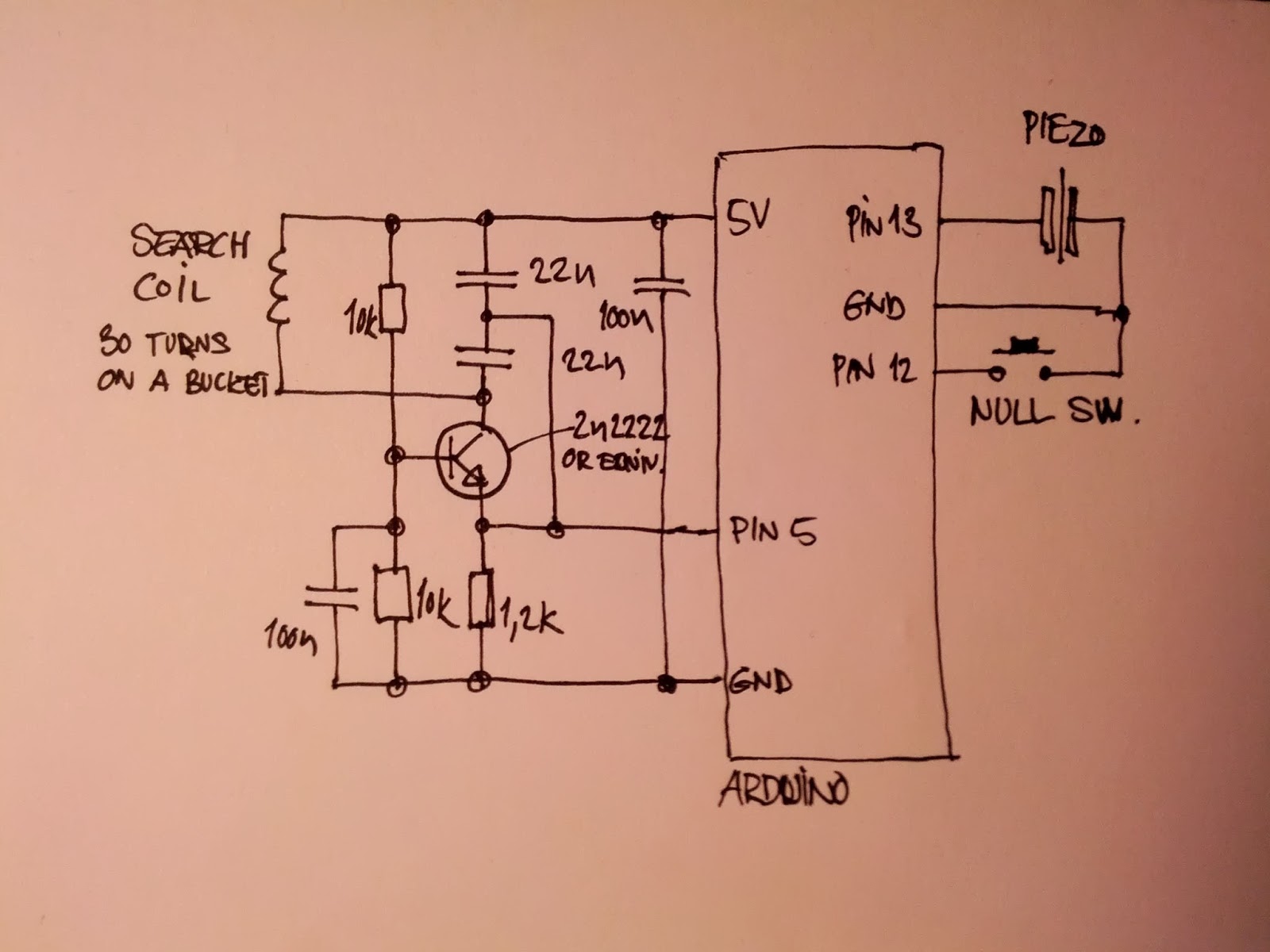
Once I finished my microcontroller, I did a little research on metal detector circuits using inductive coils, and I found a pretty cool tutorial that I thought would be helpful. This is a blogpost that looked simple enough to follow, and I understood the drawing of the circuit well enough (or so I thought).
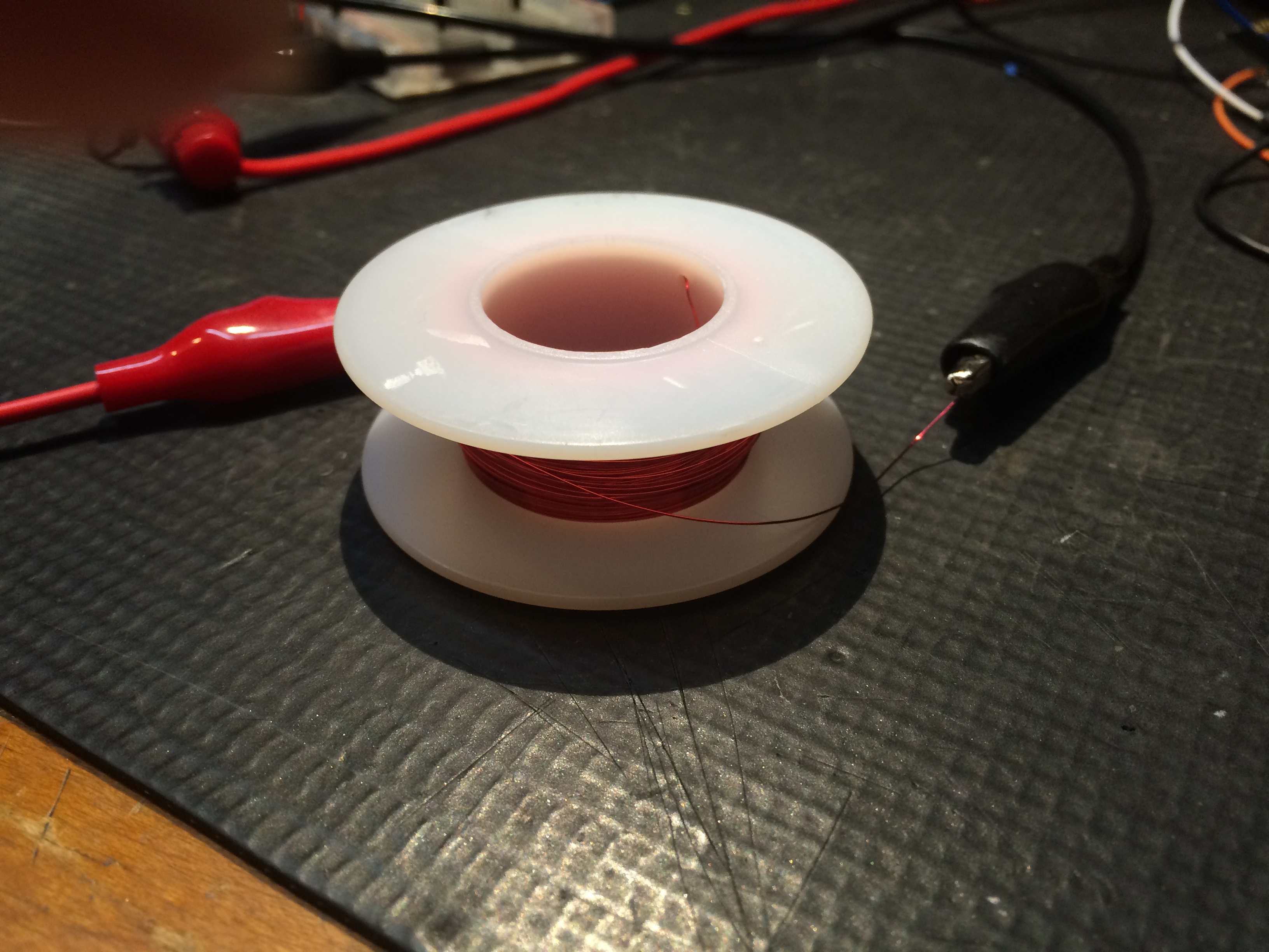
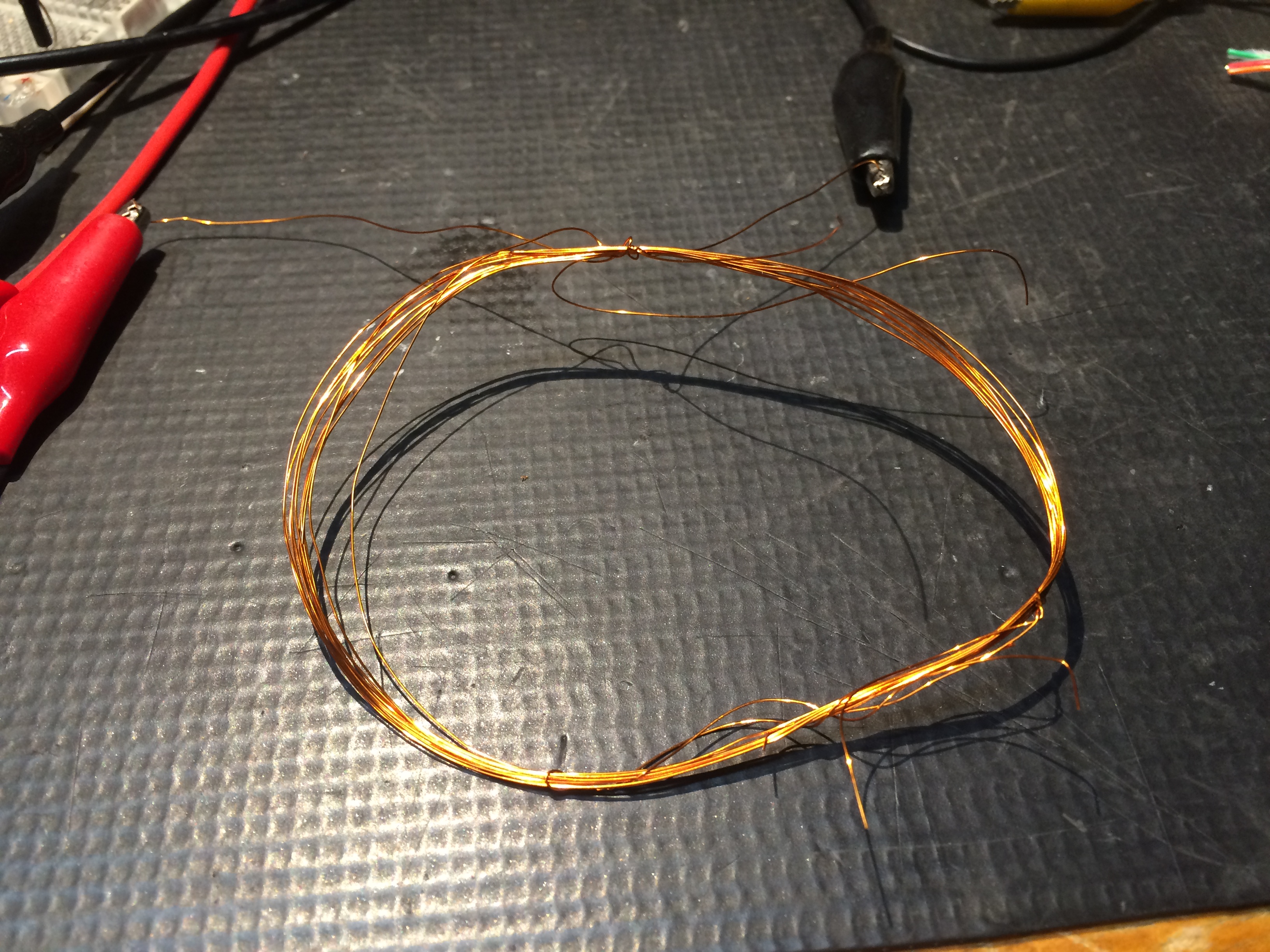
I needed to create an inductive coil that would work on the above circuit, so I breadboarded a prototype and began trying different coils (chaning the diameter and the length) until I found one that worked.
Here are some of the coils that I tested.
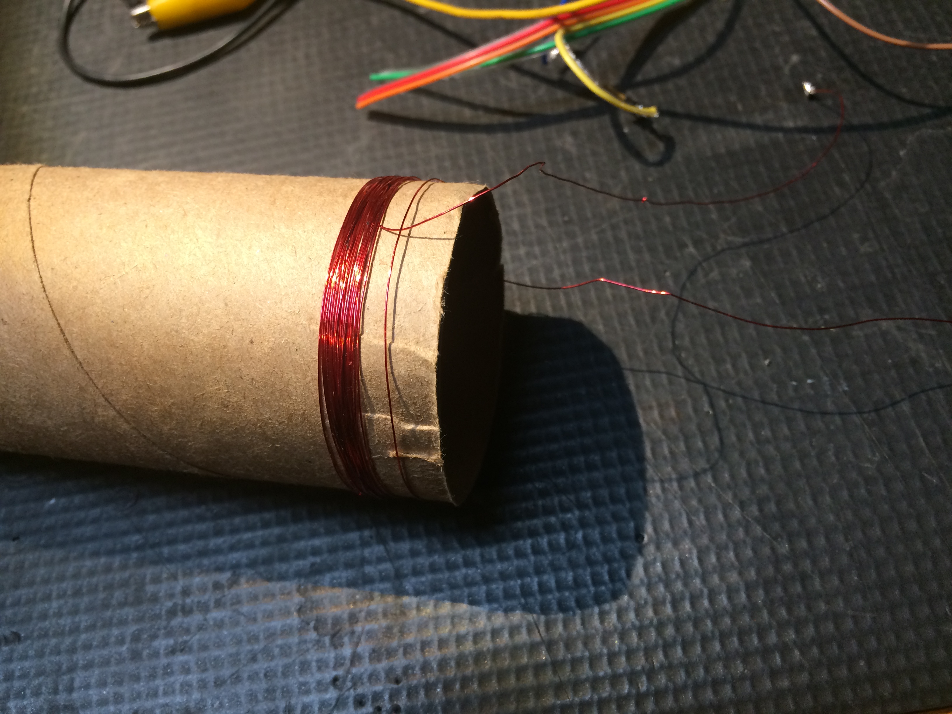
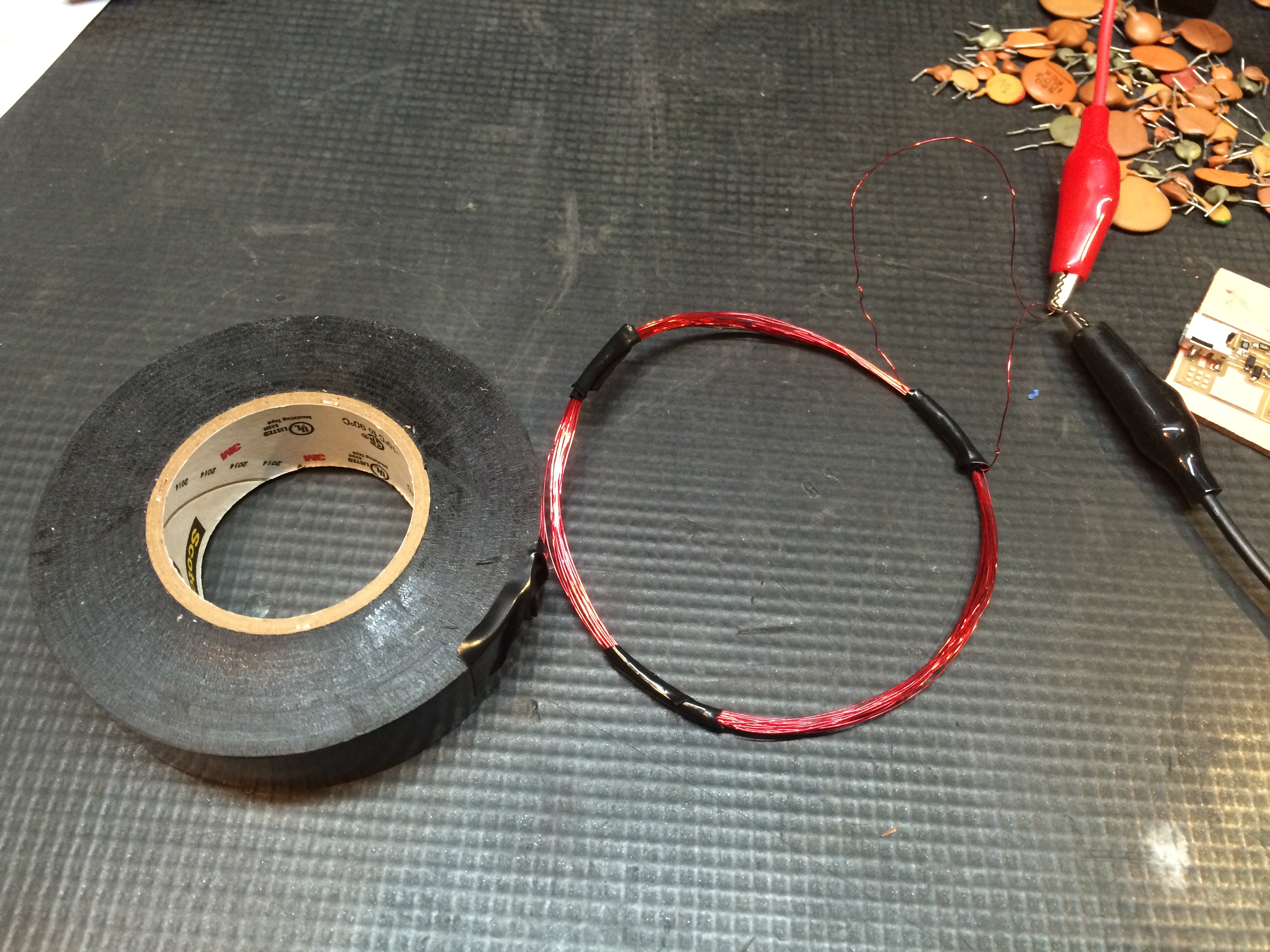
I finally figured out a working coil.
Once I had a working coil, I designed this circuit using Eagle. I decided to use 6 pin headers both to connect to the microcontroller board and also to connect to the coil. I know we had these in inventory, so I thought it would be easiest to use them.
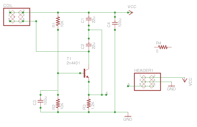
The problem with the schematic in the referenced tutorial (the handdrawn image above) is that I couldn't understand what he had written in for the capacitor values, and when I finally decifered the hand writing, I realized that it didn't really matter because we didn't have those capacitor values in stock. The important capacitor in this schematic is the one included in the inductive capacitor loop (C3). But, I also thought I'd test C1 and C2 as well. So I soldered some leads onto the circuit board that I had milled, and I jumped to a breadboard where I tested various capacitors trying to find a working combination (using capacitors that I had in stock).
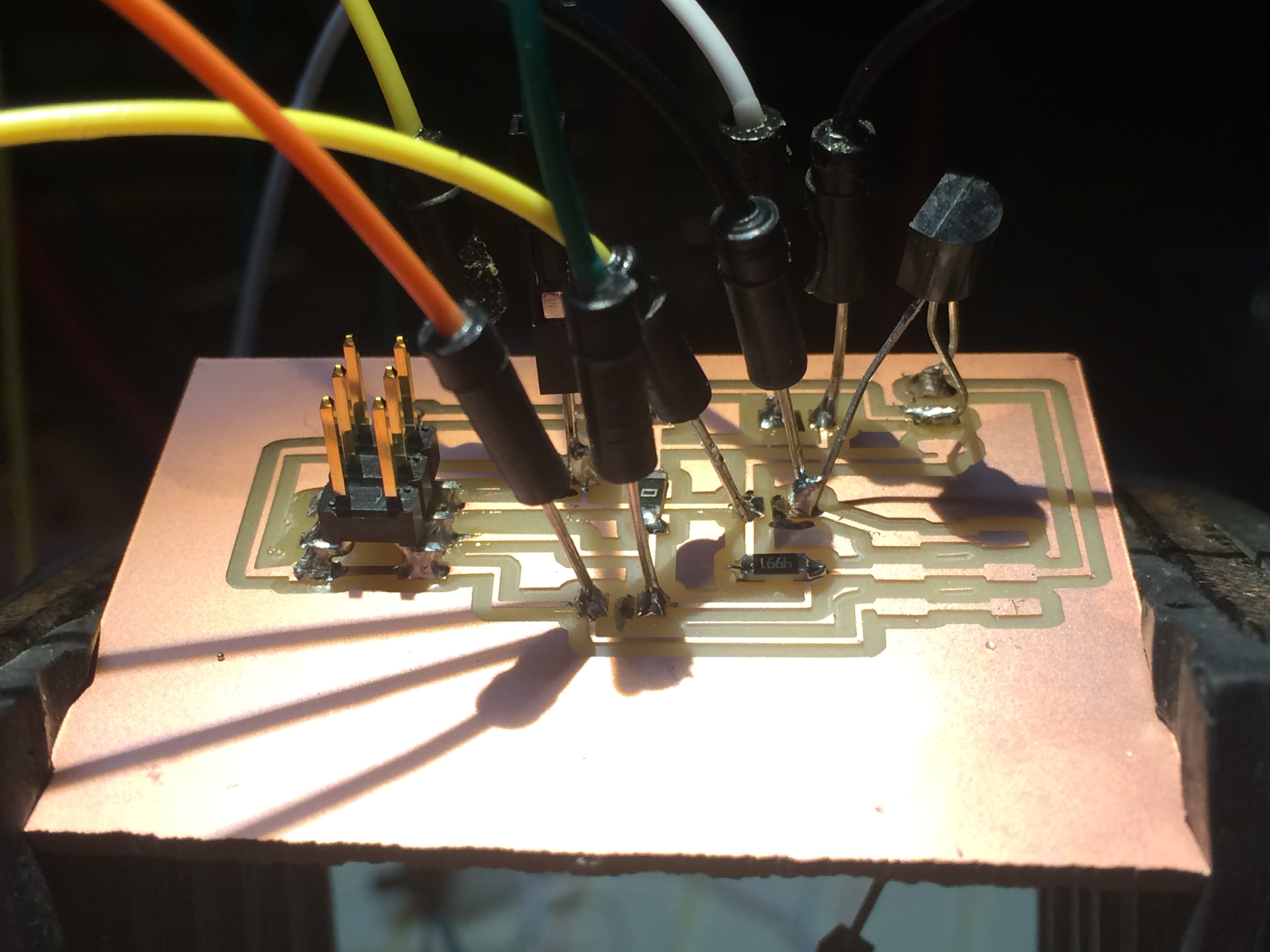
I also had trouble finding a top-mount resonator to use for this board, so I ended up using one with legs and creatively soldering it onto my board. It worked fine, but looked like a daddy long leg on top of my nice board.
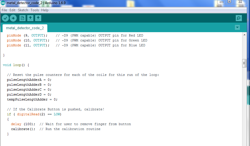
Programming the board was the most difficult part, and that was where the datasheet for the ATMega328p came in handy, as I used the pinout diagram quite a bit to assign pins. I also needed to know which pins were pwm and which weren't for my program.
Since the inductor coil is a LC loop with a changing resonate value, it is important to calibrate the loop without any metal or conductive objects in it to determine its base resonation. I had to have a calibration code that was used in the program. The calibration code can be found here.
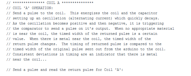
Here is how I understand my input device circuit to work:
Here is the entire project code that was used in input devices, output devices,and interface and application programming.
I did another input assignment well after the above part was documented. This time, I used my modified Satshakit board to run an input button board.
I first built my board during the output devices week.
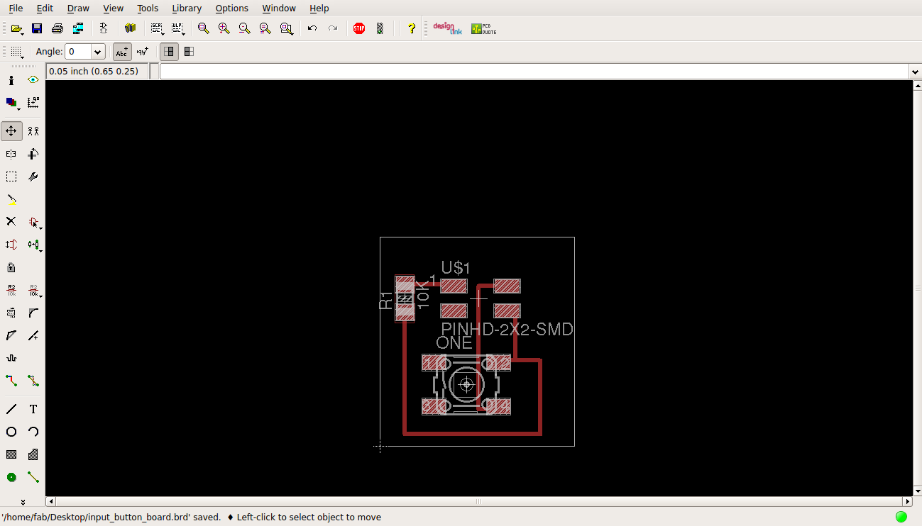
To start the new input board, I designed a simple button input board using Eagle.
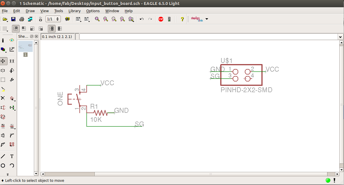
I figured out the labeling function in Eagle, and I found it to be a very quick way of wiring a board. First you draw a short lead wire from the device, then you add a label, and then you switch tools to rename the label. If your label name matches another label in your schematic, a warning message will pop up asking you if this was intended.
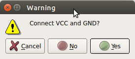
That warning popup is a good indication that your connection has been made, so that the yellow ratsnest wires will show up correctly in the board diagram. Here is the wired board in eagle.
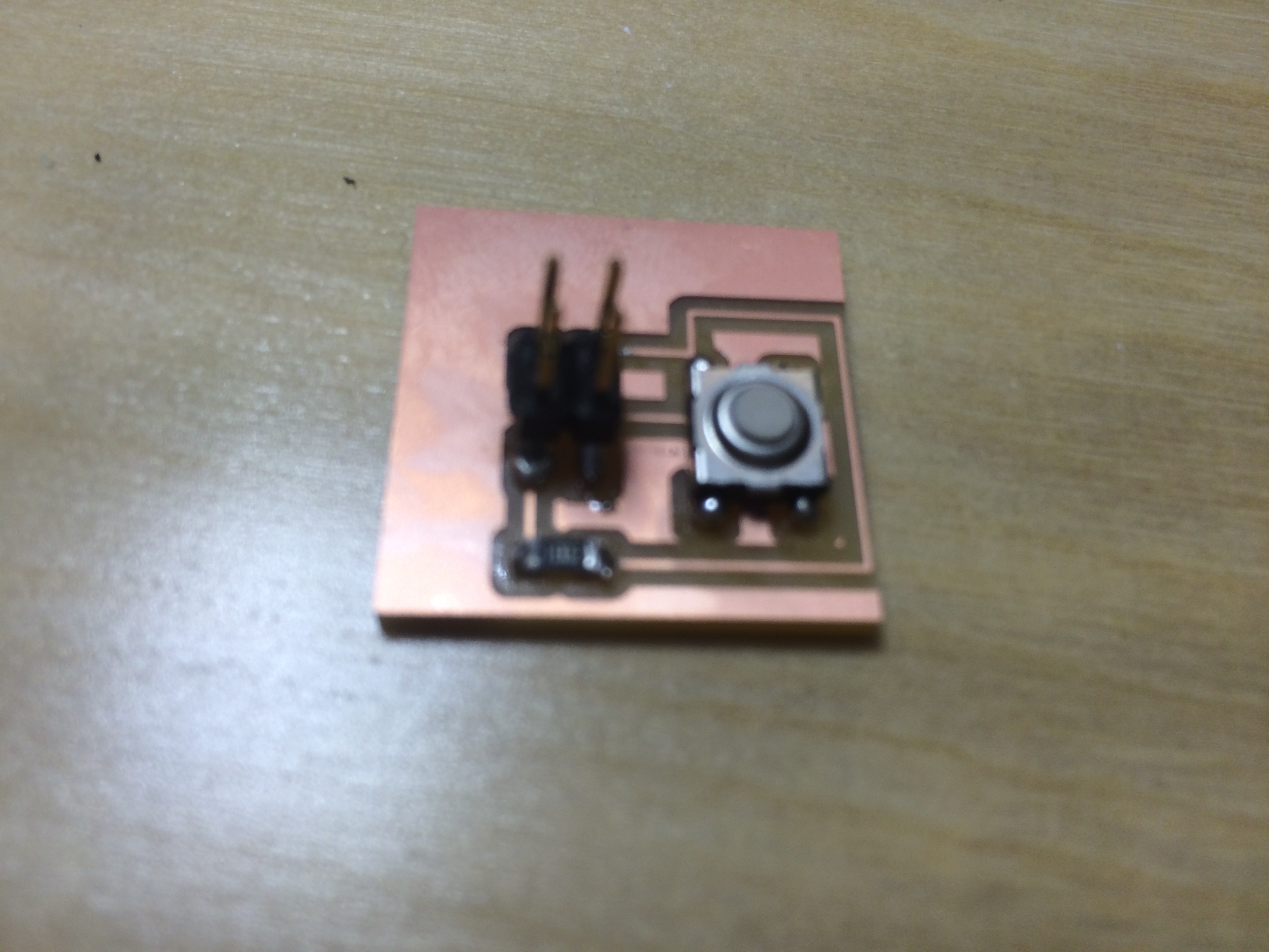
This was a smaller version of the 5 button board I built for machine design week, and I changed the header pins thinking it would be easier to make a cable to interface with the modified Satshakit board if I used a 2x2 header instead of flat pins. And I was kind of right... more on that later.
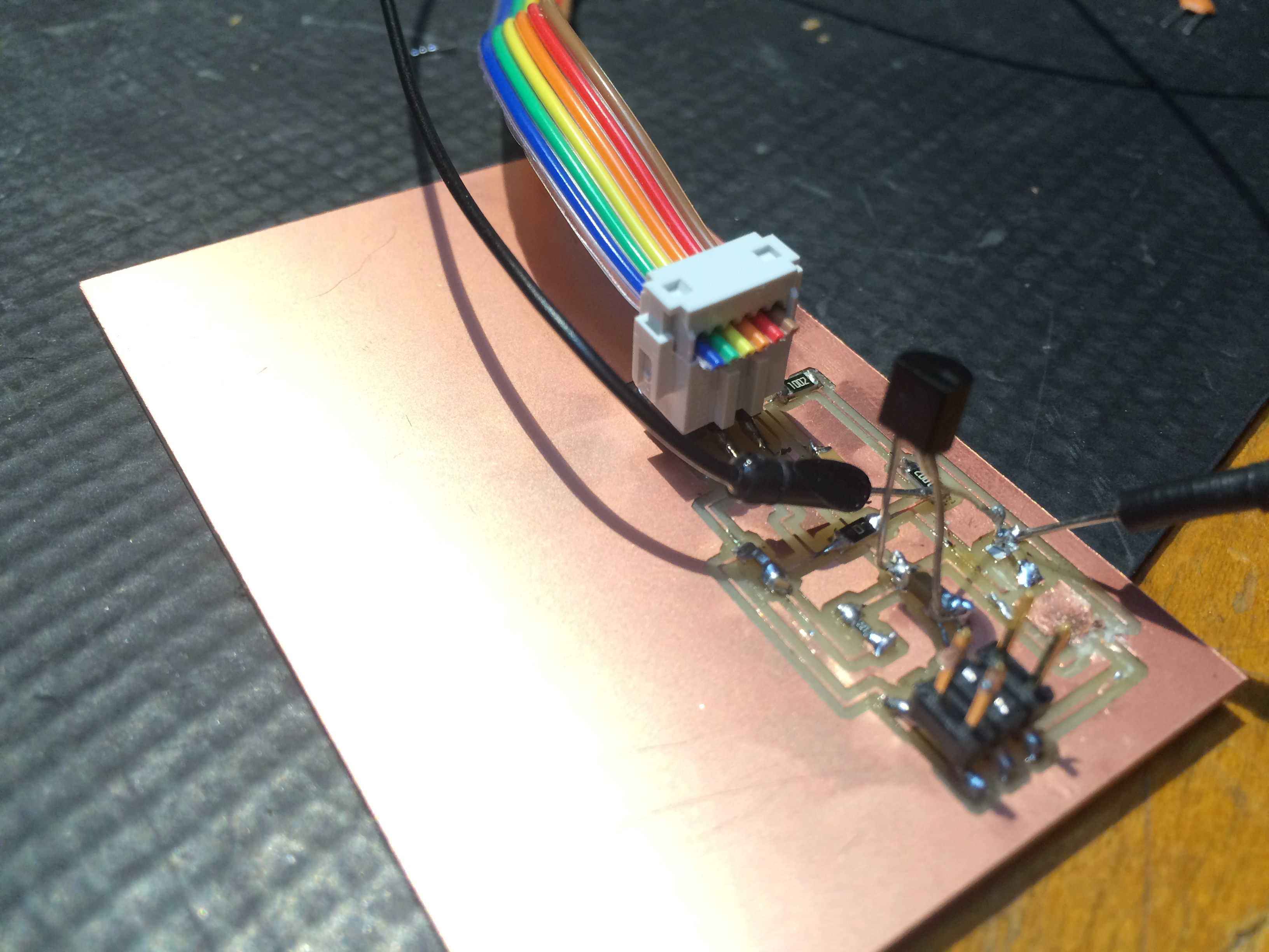
Here is the button input board stuffed and ready for connections to the controller.
My original Eagle design files can be found here:
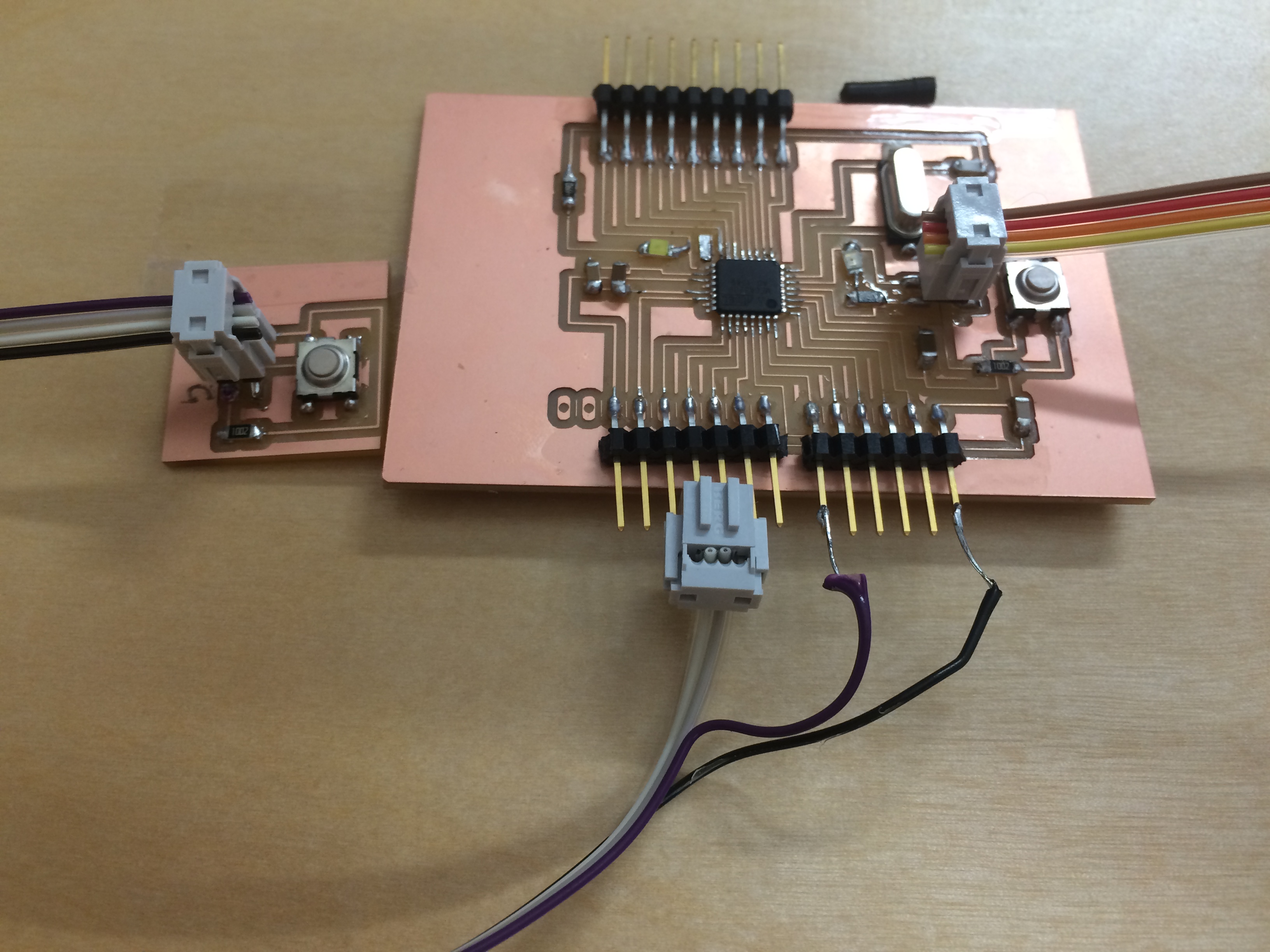
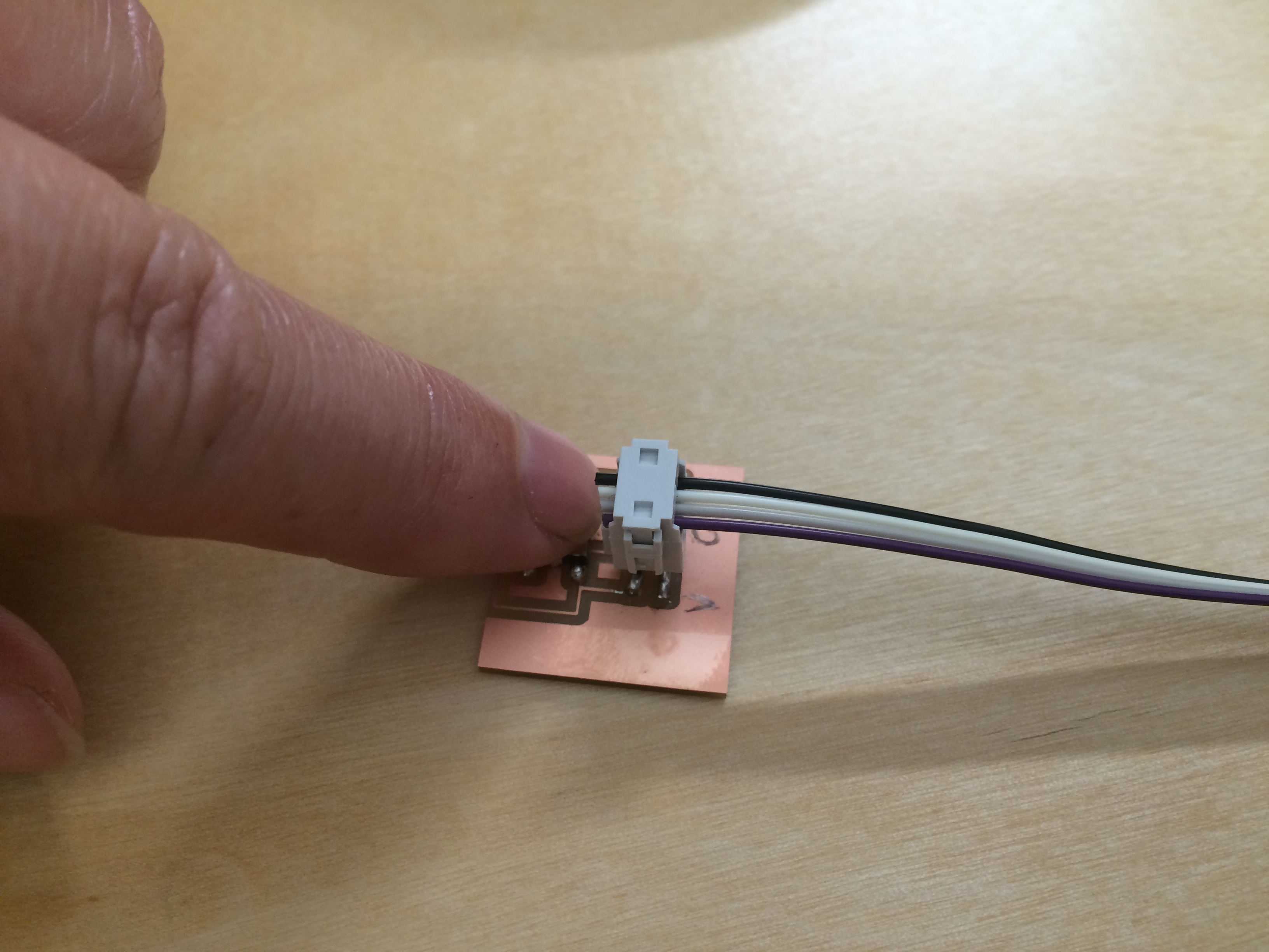
So, connecting to the modified Satshakit board was a creative process. I made a cable I like to call "janky cable jr." The purple is VCC, the black is GND, and the two neutral colors are for signal (though I only use one pin).
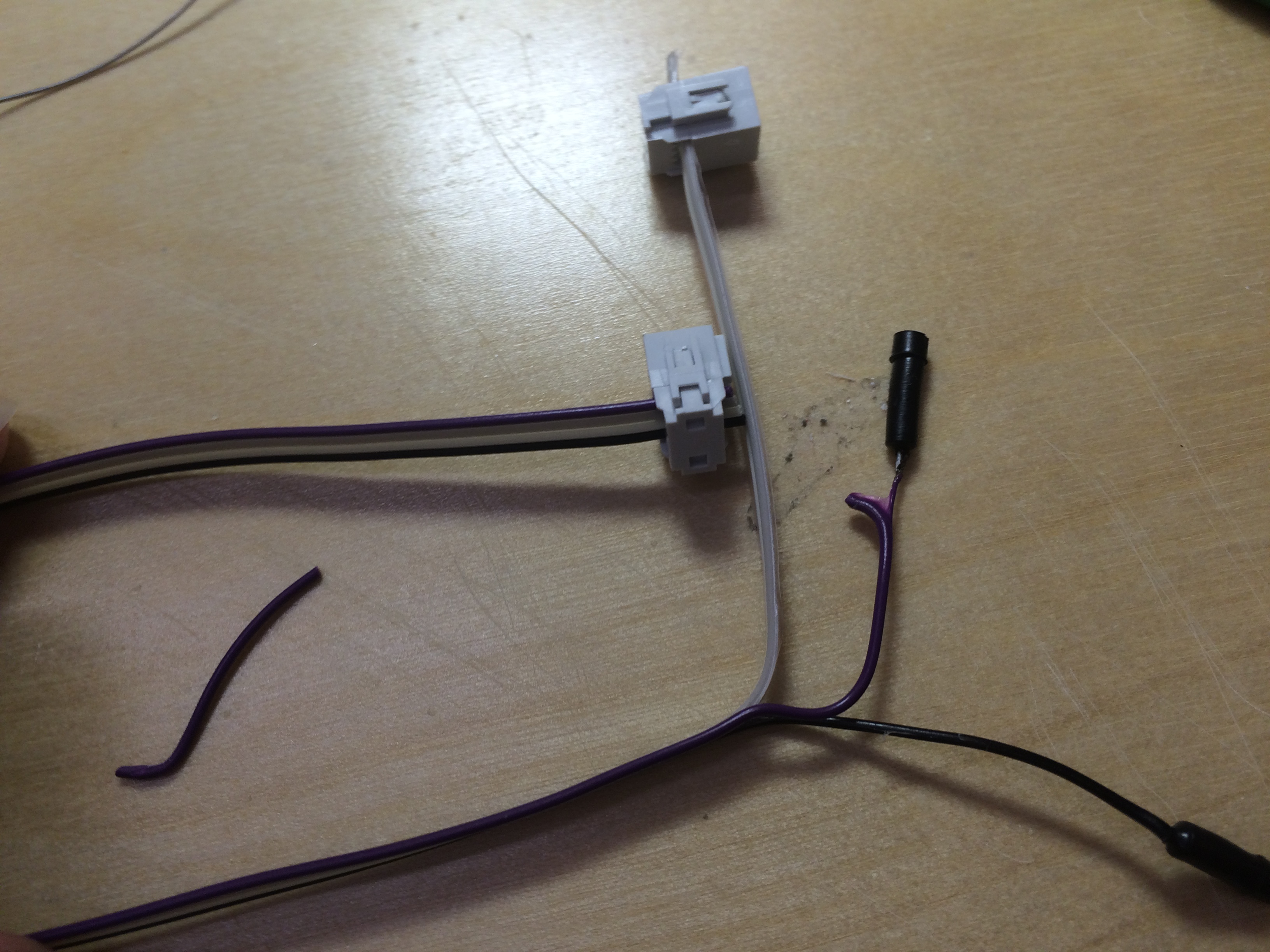
My connectors ended up falling apart after unplugging them a few times, so I just soldered them to the board. This is not ideal, but it works. The four receptacle connector wire is just to power the modified Satshakit board. The board itself is programmed using the arduino (which is exactly why I chose to modify this board for my Fab Academy adventure)
And here is how I connected it to the arduino (used as an ISP) to program the board.
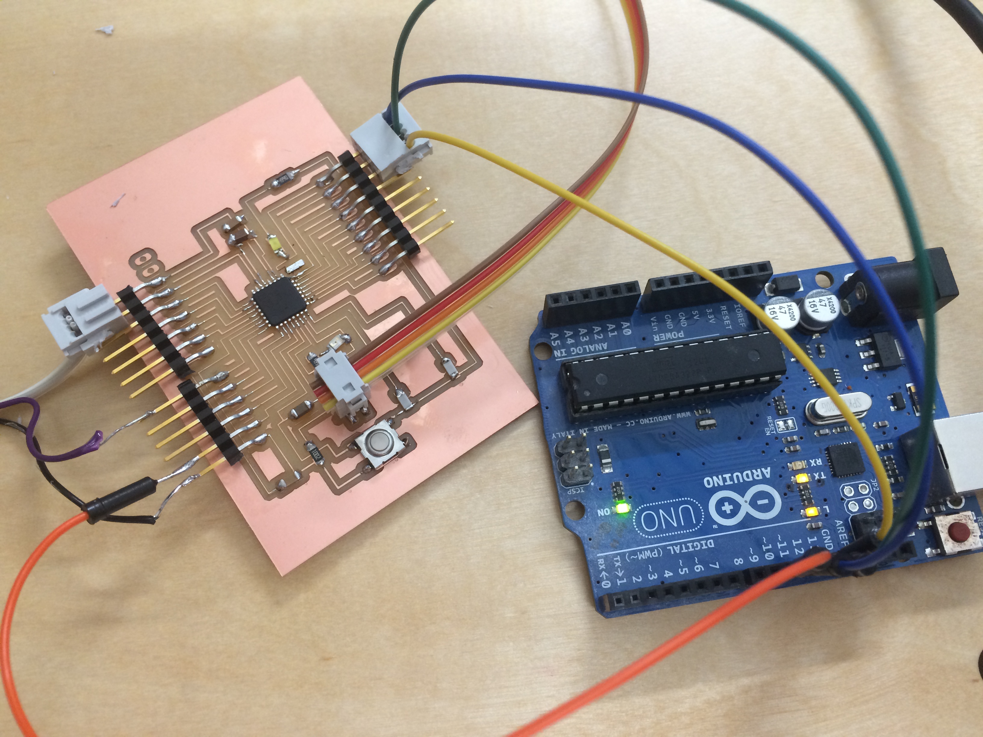
Here are the steps I took to set it up:
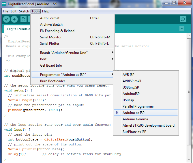
In order to put the actual program on my modified Satshakit board, I had to select File>Upload using a programmer. Thanks to the excellent documenation from the Satshakit git repo this was pretty straightforward. My biggest issue was the connector cables.
To program my board as a button input, I began with an example sketch in Arduino IDE "DigitalReadSerial." I changed the button input pin, and found that this simple program keeps showing feedback repeatedly, so I slowed the delay from 1 to 200. It goes through the loop and if the button isn't depressed, it reports 0, if the button is depressed, it reports 1.
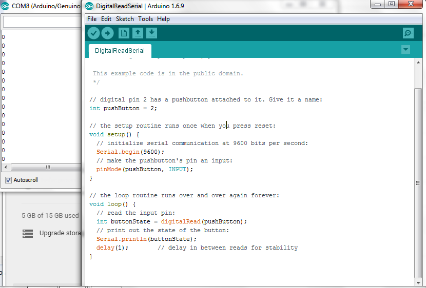
Here is the test file program.
I didn't like the fact that it kept printing with no delay, so I changed the program instead to only Serial.Print if the button is pressed. I kept the delay, but now the serial monitor only reports a Y whenever the button is pressed.
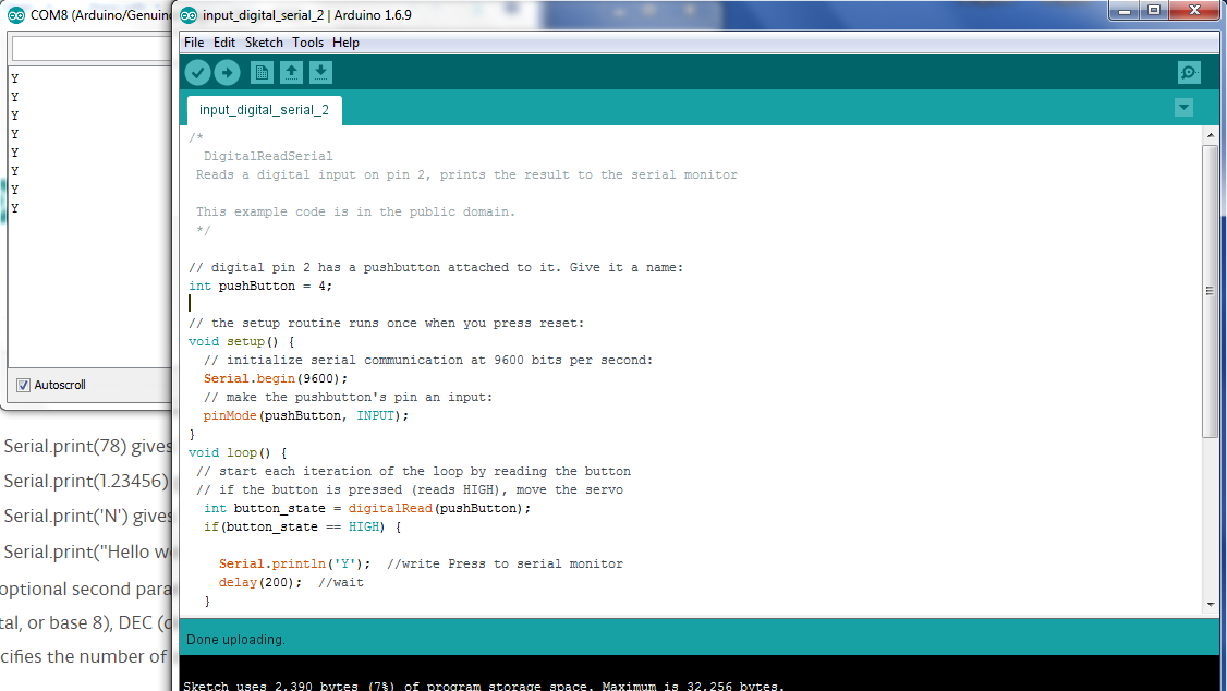
Here is the second version of the program.