Week 11:
Input Devices
Objectives
My geranium is dying. How am I suppposed to have a beautiful vertical farm desk for my final project when I can't keep a plant alive? I am making a humidity sensor for plant soil.
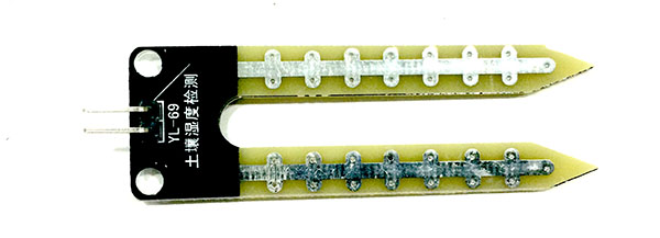
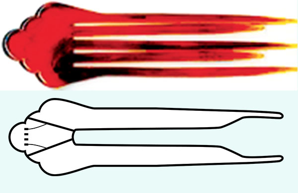
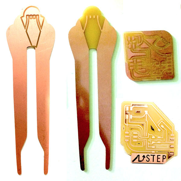
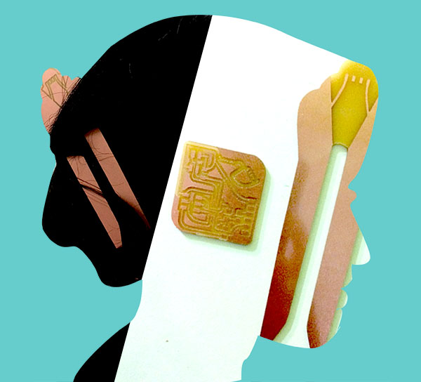
The shape of a commercial one is like a chignon pin. I will emphasize that.
Software
- Eagle
- Illustrator
- Photoshop
- Gimp
- Python
Machines
- Roland MDX-20 for milling
- Roland SRM-20 for milling
- Weller WHS-40 solder unit
Vocabulary
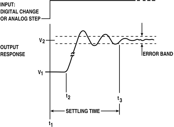
STEP RESPONSE. "Step response is the time behaviour of the outputs of a general system when its inputs change from zero to one in a very short time." Why it matters: "From a practical standpoint, knowing how the system responds to a sudden input is important because large and possibly fast deviations from the long term steady state may have extreme effects on the component itself and on other portions of the overall system dependent on this component. In addition, the overall system cannot act until the component's output settles down to some vicinity of its final state, delaying the overall system response. Formally, knowing the step response of a dynamical system gives information on the stability of such a system, and on its ability to reach one stationary state when starting from another." ~ info from Wikipedia
CAPACITANCE. When we are looking at this, we are measuring discharge that occurs when something measurable (a human body, a plant, anything organic, essentially, that contains water) comes into contact with the capacitance field ~ i.e., the largish areas of copper. Larger areas of copper produce more sensitivity because they collect more electrons, and therefore the discharge has a greater "step." There's a balance between too small to read and too large for an effective reading.
Objectives
- class objective: make a board with an input and program it
- personal objective: make a board with a non-rectilinear outline; make a board that has to do with plants, probably humidity, to turn, eventually, into sound
Practices
BASIC STEPS TO CONNECT SENSORS:
(1) Choose - (2) Design - (3) Mill - (4) Stuff - (5) Connect - (6) Program - (7) Record
And the files.
And, finally, some research and methods on Application.
Here's a little more elaboration on the list, before going into a mountain of details:
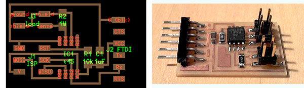
- Redesign one of Neil's boards in Eagle.
In Neil's list, you can find the schematic. Go to the CAD file for extra notes on parts (search for the part name).
See the refresher on Eagle here. - Mill it. Stuff it.
- Program it.
GOING THROUGH THE STEPS IN MORE DETAIL
(1) Choose.
- Pick your input board. Important reference is Neil's page on input sensors.
- Some other good pages on the process:
- Ferdi's page on this week is really clear on what to do
- see Irina Chernyakova's page on programming
I want to look at humidity sensors.
- Youssef Bouali on humidity
- Lina Monaco's Green Bricks
- other articles on plant-speak and brain activity ~
- see the bottom of this page for a sample of Mitch Altman's neuro-dreamer music
- BrainBeats
- another board that inspired me: Fabkit board
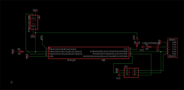
I'm starting with Neil's TxRx step reponse board plus a capacitance sensor. Where I want to get to is dielectric measurements of plants and other living substrates so that I can read how they are affected by electricity / waves.
(2) Design Board(s).
- REFRESHER / TIPS ON EAGLE
- Blum tutorial
- Fab Academy tutorial
- NB ~ the link to Fab Library for Eagle is out of date. I got it on this page, under a file download link called "fab.lbr"
START
- New Project, open a schematic window.
- Open fab.lbr that you've downloaded previously (to see how to do that, check the tutorial and Neil's class lecture page.
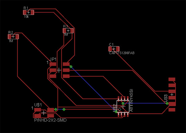
- Look at the image of the reference schematic and the component pic
- Find the parts in the library and drop them into the schematic window.
Notes on some parts:
- The J3 header you need is called "PINHD 2x2."
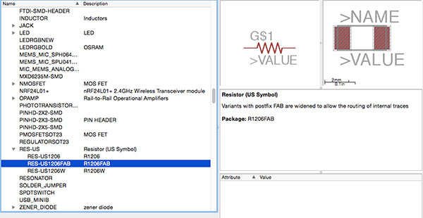
- For resistors and capacitors, choose the "Fab" footpad and type the units of resistance/capacitance you need on the schematic. Reminder of which footprint is correct for resistors in the Fab Acad inventory:
- Green is through-hole. Maroon is surface-mount.
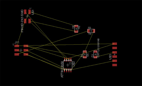
- Move parts into a rough placement in the main window of the schematic and draw connections.
- Remember the funny thing about moving groups: use the filled-in square icon in the left column to group, select the group, then ⌘-right-click (for Mac; for Windows it's control right-click) to move.
- Go to board view.
- Deal with layers:
- Layer labels in board view: I check only the top 29, and change #51, t-doc, to a bright color (it lets you see where a component comes to a footpad)
- To get rid of labels ~ click "none" so nothing is selected, then check "top" and "dimension" so that you get the traces and the board outline.
- Move things, draw traces ...
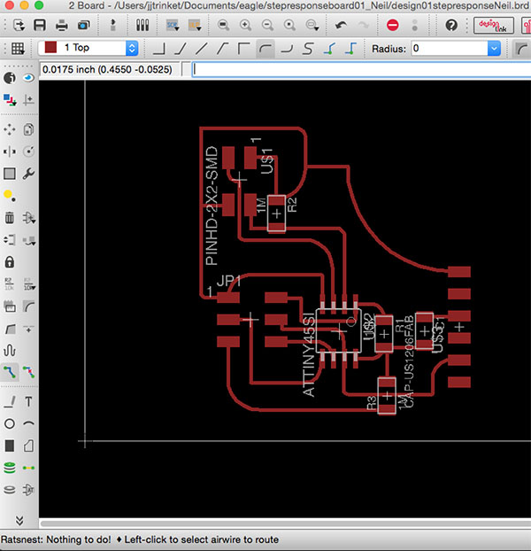
- ... till you can click on the Ratsnest icon and it says, "Nothing to do!"
- If you need to, you can make a ground pour by drawing polygon outside the board that it covers. The ratsnest will show the ground pour. You probably only need it for vias.
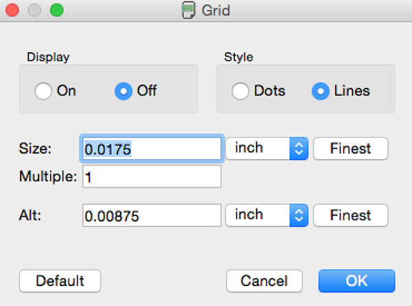
Some settings in Eagle:
- grid increments ~ start at default, then go down to .0175, with "alt" at .00875 ~ this is in inches
- settings for traces:
- autorouter net class: 12, 20, 10 ~ NB: I don't like autorouter. It's too advanced, actually! I need to do it one by one.
- tool settings: check "top" (maroon), "width" (.016), and "drill" (.039, etc.)

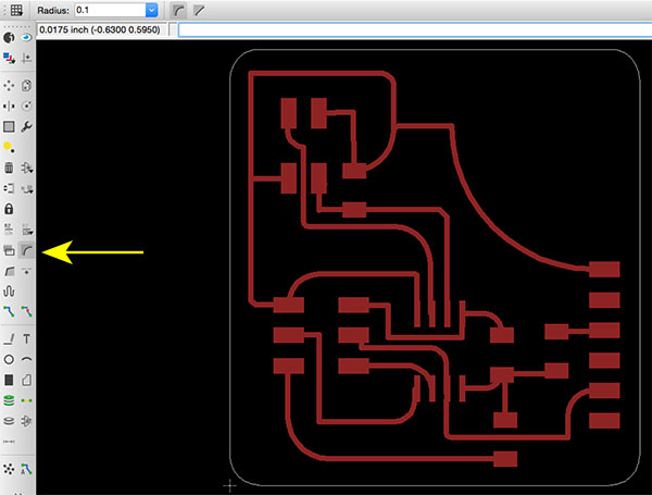
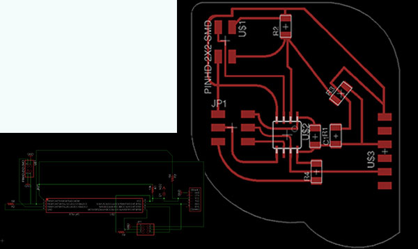
USING EAGLE TO MAKE A MORE INTERESTING BOARD DESIGN
- Changed board outline using miter tool in Eagle on the outline, which is on the "dimension" layer. See this site for more info on how to do board outlines.
- Made some of the traces thinner for a more elegant design
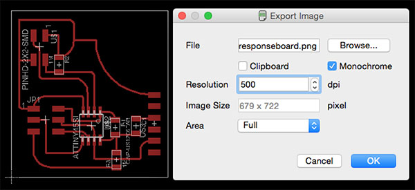
- Export only traces as .png (one layer turned on only, and it is the "top" layer)
- Export only outline as .png (one layer turned on only, and it is the "dimension" layer)
- details here on settings
- and in this image, showing settings at monochrome, 500dpi:
ADDING AN ICON
I opened the exported .png in Gimp, added an icon, and saved again as .png.
More about the genesis of the icon below.
CUSTOMIZING BOARDS MORE INTENSIVELY: SOME NOTES
I wanted my humidity sensor to look like a chignon pin for hair. I used Illustrator to draw it, using the pen tool.
- found a pic online to trace
- traced path with pen tool, using Bezier handles, in Illustrator
- saved as .svg
- exported as .dxf
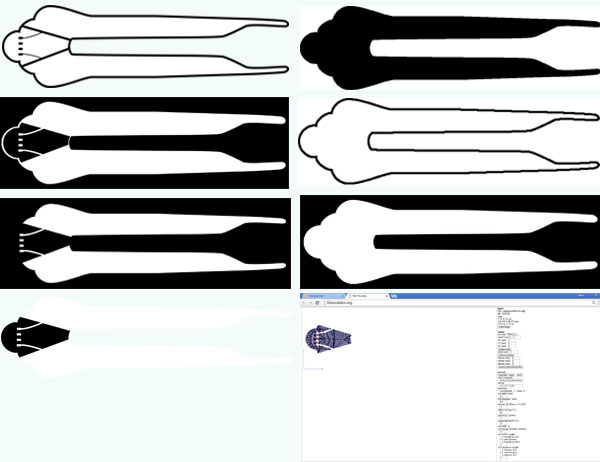
I had numerous failed designs before achieving what I wanted. Had a difficult time getting the outline file and the traces file to line up, and also it took me some effort to figure out how to mill off the copper and not mill unnecessarily over the outline. I worked in Eagle, Illustrator, Photoshop, Gimp, and the Fab Modules.
Therefore, some advice ...
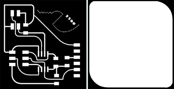
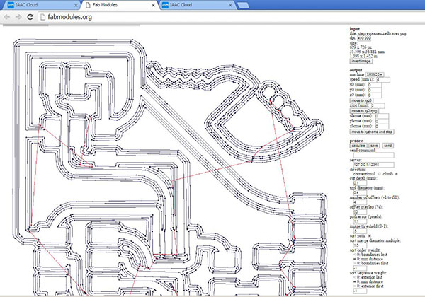
- Verify your measurements. Gimp, unlike Photoshop, has an obvious "print size" to help verify the expected output size, which you need to know to make sure a) that your traces and outline files are lining up, and b) that your board fits onto the piece of new circuit board that you are putting in the mill:
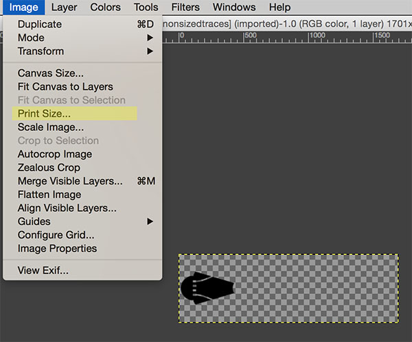
In the image above, you can see what, in the end, the .png looked like to mill out the copper 100% only in the area I wanted. - What I now understand: the module finds the edge of the black spaces and creates the path for the mill to cut based on that.
- NOTE: to make yellow instead of copper, use "-1" offset in fab modules. This commands to mill to take away ALL the black in the file.
FAILED ATTEMPT TO IMPORT A PATH FOR A BOARD OUTLINE INTO EAGLE
- To make a custom outline, either DIRECTLY adjust the outline layer in Eagle, or open the file in Photoshop, Illustrator, or Gimp and add the outline in one of those programs. I tried for a long while to make an outline and IMPORT into Eagle ~ this is nearly impossible. It involved installing a lot of "ulp"s that didn't work ~
- Attempted to import to Eagle via this tutorial
- Eagle crashes every time.
- I am using these 3 ULPs:
- I also tried importing directly. I am using Eagle version "7.5.0 for Mac OS X (64 bit)Light Edition."
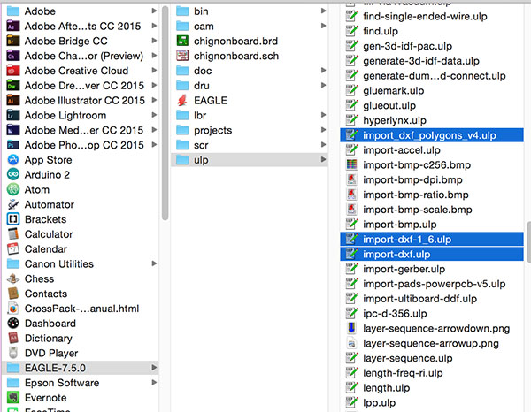
After a lot of time trying to run a ULP to import a .dxf or .bmp from Illustrator, I abandoned this and went straight to Illustrator to draw the .png to run in FabModules.
In designing, I referred to the work of / was inspired by Ani Liu, Matt Blackshaw, Francesca Perona, and Arnau Tasies.
(3) MILL BOARD(S)
- To run the Roland Mill MDX-20 for PCB milling via Fab Modules on Ubuntu:
- In Terminal, open the home directory
- type "fab" ~ opens a GUI
- format: image
- process: .rml MDX-20
- make_.png_rml
- another GUI window will open
- load .png
- check its size in mm
- at top, go to "defaults" and set your mill (for traces, 1/64)
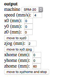
- select the machine on the right side ~ here's that panel:
- click button: make .path
- check the path ~ everything look okay? Nothing is connected that should not be connected?
- click make .rml
- click send it!
- Open V-Panel.
- zero the spindle by entering numbers into "xmin" and "ymin" and clicking "move to min, ymin" till it looks where you want
- push "up" and button down for "z," finger-feel the z as with other tools to zero the z
- save the coordinates by clikcing the origin buttons on the right
- Load the .rml file by clicking the button that says "cut."
- As soon as you click "output," the mill bit will begin to spin and follow that path.
- Start at 70% or so to verify things look right, then go up to 100%.
- Press "pause" for problems.
This is a good page on the process.
Straightforward, right? It seems nothing is straightforward!! Spent night of 29 April fighting with a Linux system that crashed repeatedly when I tried to retrieve files to load in Fab Modules for the Roland Modela MDX-20. It seemed all my files were sized well, then I would open in FabModules, and I'd see unexpected sizes. Getting images loaded, lined up, the drill lined up, breaking the drill bit, etc ... it took hours.
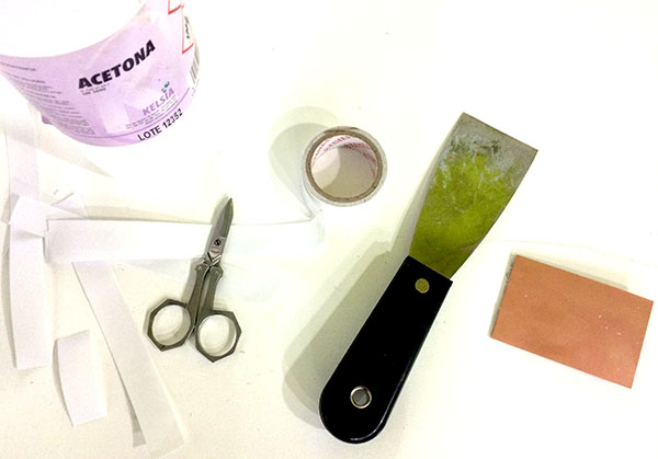
Supplies used:
Not going well:
PROBLEMS WITH MILLING
- A problem with the CHIGNON BOARD ~~~
- Mill bit too far out: I broke a mill. It seems I tightened the alan screw on the collet down onto the collet, not the bit, b/c the mill bit was not far enough up into the chock. This is difficult to check ~ you just need to know the mill only comes out about 10mm.
- Mill bit was too far in! WATCH OUT FOR Z ... The mill was having a strange behavior: it would touch the circuit board and rise, then it would cut when it was about 100mm in the air. Why? Ah ~ when the -z was set, it was set at its maximum down. That means I put too much of the mill into the shaft, and the machine couldn't move down any further to mill the substrate. Not to mention that the mill had seemed broken, and it was!!! Hence, there was not much to set it on ...
After resetting the depth of the mill with a new bit, the SRM-20 hums its nice tunes.
- A problem with the STEP RESPONSE BOARD ~~~
- First step response board didn't work; I destroyed it when trying to lift the processor chip off.
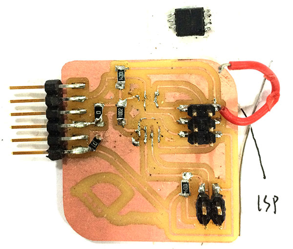
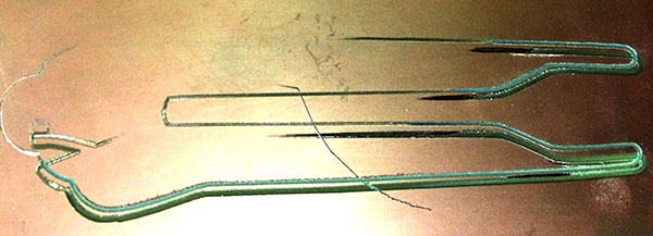
I carefully milled another based on a -1 offset design. I started w a cut depth of .1 and sent the file a total of 3x, going down 0.5mm each time: cut depth of .15 and cut depth of .20. The unevenness meant some parts got milled totally while others were just barely scratched, hence the minutely increasing increments on the "z."
The words are not visible ... will figure this out at another opportunity.
However ...
The board will NOT lie flat! This video shows why it matters:
If your board does not mill evenly, try going down incrementally each time:
- 1/64 mill = .4mm diameter; cut depth ~ start at -1.7mm
- 1/32 mill = .8mm diameter; cut depth ~ adjust -.1mm at a time
- Problems using Ubuntu on Linux for FabModules to mill on Roland MDX-20
- Ubuntu command to give permission to get the serial port, in Terminal:
sudo chmod a+rwx /dev/ttyUSB0 - Opening Firefox (to get files from IAAC cloud) led to repeated system auto-shutdowns and then, finally, an irremediable freeze. Linux quit process from terminal is: cntl-alt 4 to get to console
- This didn't work. Hard shutdown is alt + sysq and then type the following in order:
R E I S U B - And actually that all still didn't work. Another day ...
PLEASE NOTE: After milling, I forgot to use steel wool and dish soap to clean my boards. I soldered directly. I was having a hell of a time soldering, and I think it was both more difficult and didn't work because I forgot this step!!!
FILES
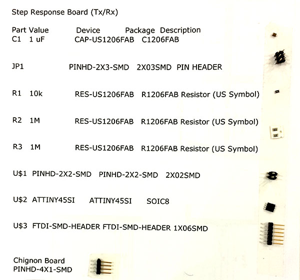
3 .pngs for (finalized) Step Response (one is .png is for words) // 2 .rml files (board size = 37 x 38mm)
2 .pngs for capacitance board // 2 .rml files (board size = 140 x 40mm)
 Back to Top
(4) Stuff Board(s)
runbomin the command line in Eagle to generate a .txt file to print; this paper is where to affix components before you start soldering- note: header pins should be well-placed on the board. Neil's illustration of this:
(5) Connect Board(s)
- Tutorial on the FabISP, as a refresher
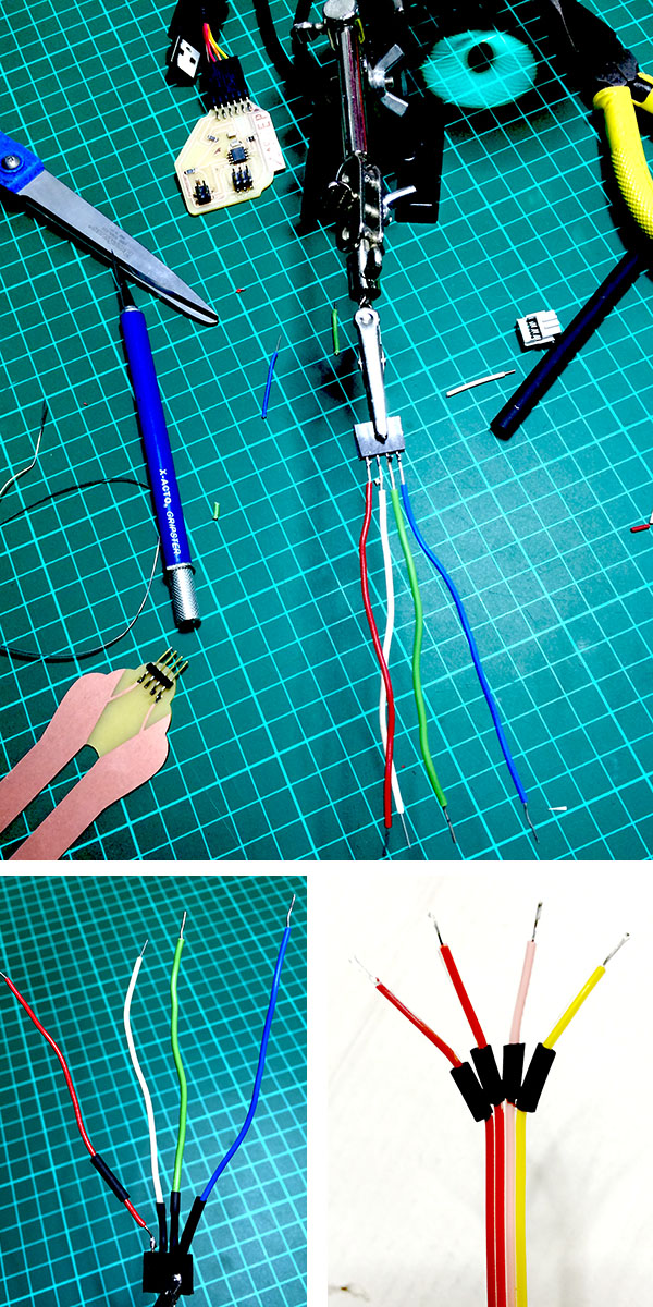
- Started with fabricating the cable I need to make my sensor work. Made a mistake. Refabricated.
- Next: connections, which way round?
- from programmer, blue is ground, bright red is VCC.
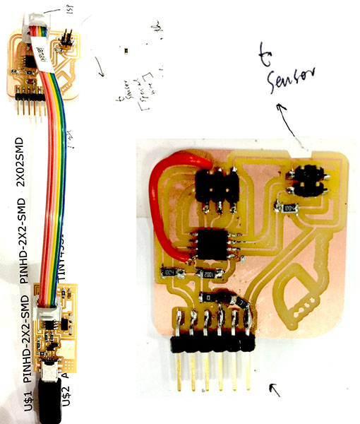
- hence, my ribbon cable from the programmer attaches thusly to Step Response board:
- You can see the FTDI above, too.
- FTDI data sheet
- plug in FTDI the right way around (black is GND, red is VCC)
- check if the FabISP is working by plugging it into a USB port on your computer via its mini-USB.
- Use the command
ls /dev/tty.usb*to find your USB active port name - Does something show up? If no, you have to close the circuit. Make sure your board is powered.

I discovered some problems when I tried to program ~ had not traced the circuit well, so I added a jumper to rectify. Still didn't work, so I eventually did a total re-design. It's the redesign that's in the files above.
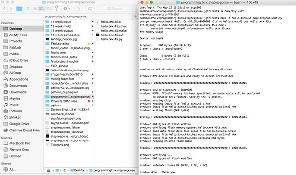
(6) Program Boards
- Program it in the following way:
- Connect to FabISP.
- Connect FTDI cable for power ~ or put a battery. Or re-solder the jumper for power to the programmer.
- Copy C program and make-file to a folder (easiest to put it on the Desktop).
- Save .c and .make with those respective filename extensions
- Change directory in Terminal to the folder.
- Run
sudo make -f nameofmakefile.make program-usbtiny
~ It is specifying the name of the file with "-f," though as soon it finds the file with "make" it is enough.
~ that command will generate two files of hex code, a .hex and a .out
~ explanation of the code you see in a makefile: You see three instructions: hex code (which goes into the microchip), output code, and which programmer out of 5 types to use ~ you don't have to comment out any, b/c you name the programmer in the Terminal code
~ brief explanation of .c and .make files: You need the makefile in C to program your chip. C tells the microchip what to do. The makefile points at your GCC (set of compiler libraries) in your computer to translate C into binary. - Now install python-tk (Tkinter library) if you don't have it already.
~ NB: Python 3 calls it tkinter not Tkinter.
~ There are many possibilities for how to adjust the GUI with Tkinter. - Download python file from Neil's examples; this will open the python window that shows output (see under "motion" for the file).
- Put the file somewhere (again, a folder on the Desktop is easiest) and use the directory commands in Terminal to get to it.
- Run
python hello.load.45.py /dev/ttyUSB0where the last part is the serial port that you are using and the part that ends in .py is the file specific to your sensor. - Python should open a window showing you input from the sensor turned into visual data.
- Type "make clean" in Terminal if you mess up and need to start over with the programming of your chip.
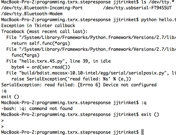
A little mistake ...
I unplugged board while program was running. Oops. I tried to exit Python by running command:
exit()
But nothing happened. So I quit out of the Python application. When I returned to Terminal I still didn't have my prompt, but had a carot instead of my shell. To return to the shell, typing "control-C" worked.
(7) Record.
Video of successful capacitance measuring:
Programming files:
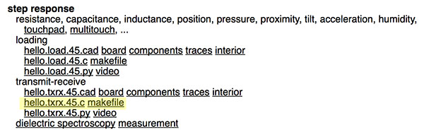
These are for the Step Response Tx-Rx board.
Application & Complication
To apply the capacitive sensor to a project requires a few more steps. You'd need to take the readings from the sensor and create code that uses "if" statements to route the readings into a variety of outputs. Though I do not at present have time to write new code that results in conditional outputs, I have commented a capacitive sensing code from the Arduino playground so that what is happening is clear, and how one would use it for further next steps is clarified. I've applied the explanation to my current sensor, the capacitive chignon.
EXPLANATION. The capacitive sensor works by attaching two pins to a sheet of electrons -- a large piece of copper, for example, or, in my case, copper on a PCB in the shape of a chignon pin. The two processor pins are wired differently and coded separately. One of the pins is the send pin, and it connects to the copper field via a large resistor, something like 10M ohms (much larger than we use for standard pullups or pulldowns). The send pin (which is pin 4 in the code below) sends out a square wave, which is slowed down by a big resistance, crosses the copper surface, and reaches the receive pin of the Arduino, which in the code below is pin 2, also called the sensor pin.
Why the big resistance? When you put a human body or other dielectric medium to the copper surface, the electrons are pulled through the resistor more easily. The charge resides in the big fat organic stuff (i.e., body, or other thing that functions as a sink), before that thing gets replete and passes the charge along, where it is received by the Arduino pin (in this case, pin 2). Since, if you take the organic half of the capacitor out of the system, you should get a constant flow at a particular time, you can measure different materials' different capacities by changing out the half of this embedded system that is not the copper. In the real world example below, I switched the human hand for a plant in wet soil, to see how the readings might or might not produce enough of a level of difference so as to be useful in writing code that could sample the readings to create a usable output.
In case it is not clear, what is useful for the code is seeing the difference in the numbers based on the physical conditions affecting the copper field. The conditions affect the reading from the receive pin, which is counting time via program ticks. So a greater resistance means more possible variety in timing, which equates to more sensitivity.
You see the difference in the numbers via the serial monitor.
This good explanatory video includes this relevant part:
Now, here is the commented Arduino code for a capacitive sensor -- please note that you need the Capacitive Library from Arduino to run this, and you can find that here.
#include <CapacitiveSensor.h>

/*
 * CapacitiveSense Library Demo Sketch
 * Paul Badger 2008
 * Uses a high value resistor e.g. 10M between send pin and receive pin
 * Resistor effects sensitivity, experiment with values, 50K - 50M. Larger resistor values yield larger sensor values.
 * Receive pin is the sensor pin - try different amounts of foil/metal on this pin

 Commented by Janaki Ranpura, Fab Lab BCN, 20170707.
 */

CapacitiveSensor   cs_4_2 = CapacitiveSensor(4,2);        // 10M resistor between pins 4 & 2, pin 2 is sensor pin, add a wire and or foil if desired
                                                          // to be clear on how to wire: pin 4 sends a square wave from the Arduino,
                                                          // it passes through high resistance to a copper field (connect pin to big resistor to copper)
                                                          // the copper field + body or other dielectric material creates a capacitor
                                                          // the copper field is connected to pin 2, which is coded as an input
                                                          // the serial monitor states how many program ticks passed between the square wave output
                                                          // and the square wave receipt as input on pin 2

void setup()
{
   cs_4_2.set_CS_AutocaL_Millis(0xFFFFFFFF);     // turn off autocalibrate on channel 1 - just as an example
   Serial.begin(9600);
}

void loop()
{
    long start = millis();                        // this is milliseconds
    long total1 =  cs_4_2.capacitiveSensor(30);   // this is program ticks
                                                  // this means that the two numbers you see in the serial monitor
                                                  // are not in the same units

    Serial.print(millis() - start);        // check on performance in milliseconds
                                           // the first number printed here is stating when the pin activated; it is not so relevant for our purposes
    Serial.print("\t");                    // tab character for debug windown spacing

    Serial.println(total1);                  // print sensor output 1


    delay(1000);                             // arbitrary delay to limit data to serial port
}
USING IT. Here is some data collected using these methods. It is collected to solve the question: how would I make a system to water plants based on the capacitive sensor that I have? The answer is to determine the limits of the sensor in different conditions and use those limits as the edges of conditional statements in code. I have only had time to gather some data on what the perimeters would be.
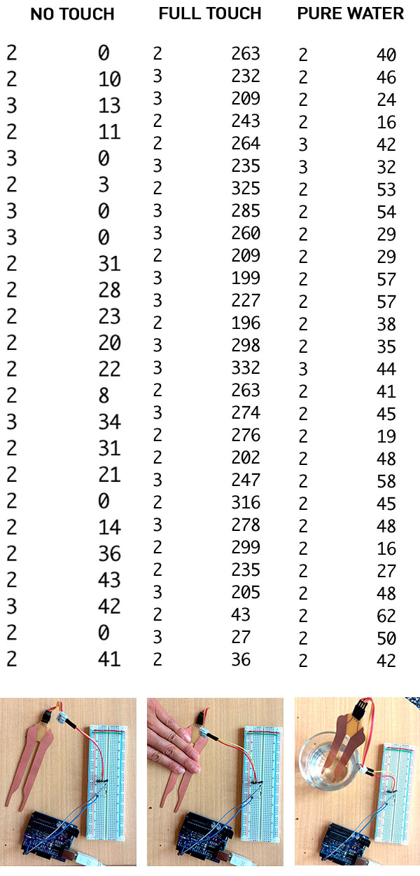
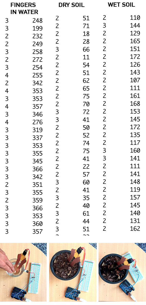
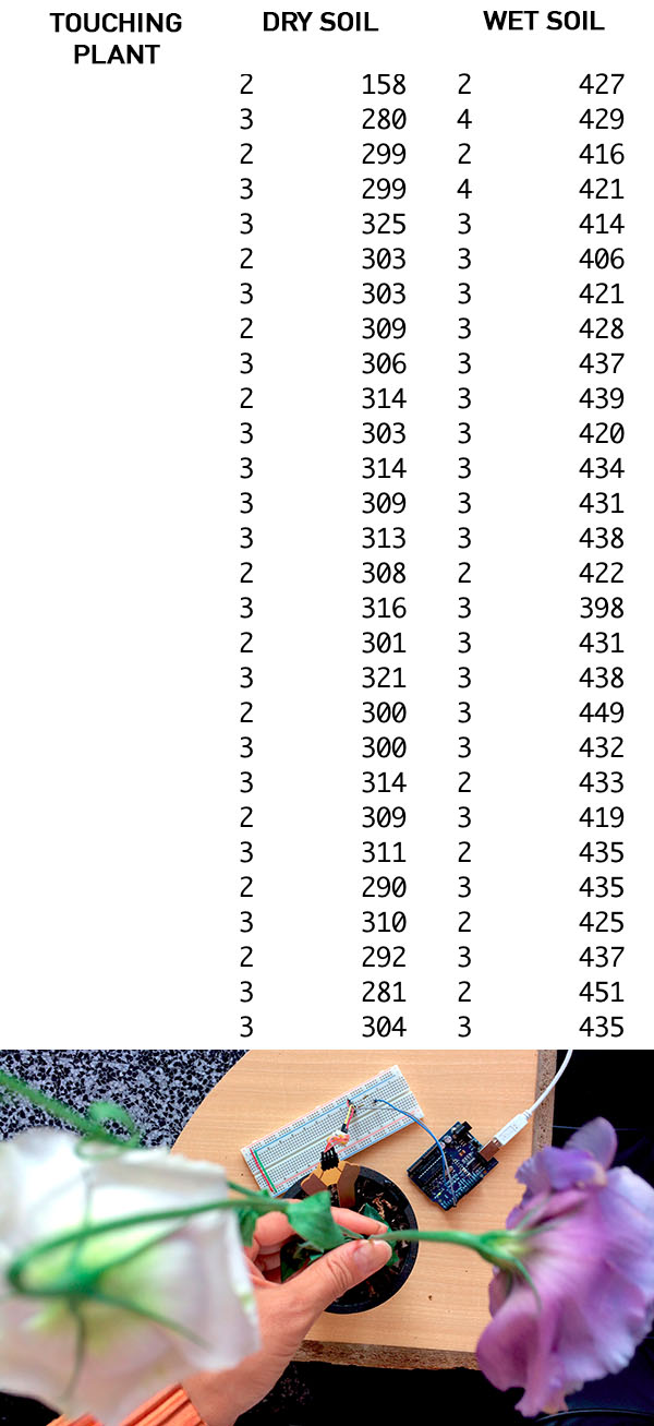
Based on the data, I would say that it would be possible to make code for this system that sends fairly reliable feedback on whether or not your plant needs water; in this case, you would need to hold your plant's leaf, look into its eyes, and ask it.
A more sensitive no-touching system would need further experimentation with the size of the copper fields and the size of the resistance on the send pin.
The idea of a hair pin that measures water or air quality based on the relative changes in women's hair in a neighborhood still totally charms me; it just would require a much more subtle system than the one I was able to build in this unit. It's yet another simple, alluring idea that is not at all simple to create.
THEORIES, IDEAS, EVENTS, INSPIRATIONS:
- Cool paper on interactive furniture. Neil is one of the authors. Forwarded by Borja Lanza from León.
- On Thurs April 28, I went to see a showcase of experimental animation at the DA film festival, on which one of our lab members, Citlali, worked!
- On the weekend, my beautiful friend Caroline Park and I went to Tibidabo ~ at the tippy-top-oh of the mountains near Barcelona, in the same area as the Green Fab Lab.


MY ICON
A little bit about my the genesis of my icon ... The icon comes from a graphic representation of "the most popular story in Western Civilization" as diagrammed à la Kurt Vonnegut combined with the date Hiroshii Ishii suggested we use when we envision the future viability of our designs: the year 2200, far enough into the future so that everyone we ever meet today is likely to be dead.


Return to section on customizing boards, or to the list of steps near the top.
And I want to recommend again Hiroshii Ishii's talk.
- Notes from it:
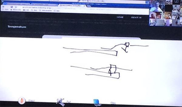
- Nice under-the-water, out-of-the-water metaphor about technology ~ what we see is "out of the water," what makes it work is often "under the water."
- Sandscape, where you can model the geography and map it to water.
- I love this man! For "inForm" dynamic tactile display, he says, "Don't ask why. This is art."
- He also says these technologies are to help people communicate, and the technologies are blank canvases for artists and designers to make meanings.
- We have to use vision, but we are builders, too. We have to build!