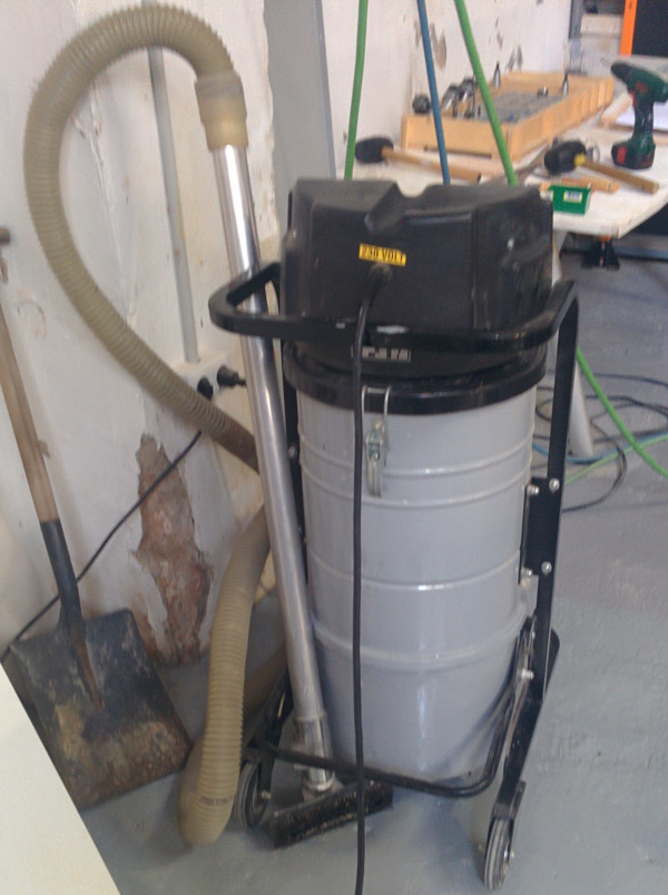
Hola. I'm father,husband,freelance,software developer, vailethacklab and bike [brompton] lover. Within 24 hours, enough time to make [almost] everything ;).
I live in Badalona, a small town by the sea and the people I love.
If you like code, music or cooking we'll be good friends.
I'm multimedia engineer, graduated at La Salle Univeristy. Although I have experience as a designer or 3D modeler, during last 10 years I have been working as a software developer and project manager at Ambar VS (co-founder).
But now, It's time to change.I really want to adquire practical capabilities in digital fabrication, feel and think as a MAKER and start new professional projects.
I already had previous experience developing websites so I decided to use a bootstrap template (freelancer) and customize it with my own code (html,css and javascript) and Brackets as a code editor. I had never used this tool so this exercise has helped me to know their characteristics and how easy it is to modify web code.
One of the most important things I have learned this week was to know and use Git.
Git is a free and open source distributed version control system designed to handle everything from small to very large projects. So, Git is our tool to keep updated and controlled all our work (code, pictures, 3D models...) during the FabAcademy. There are two ways to use Git: the original command line or any of the graphical user interfaces like GitBox. I use command line tool because I feel comfortable with it. IMPORTANT: Before you start using git it is necessary to have a ssh key!
Some Git basics:
[Clone an existing repository_ $ git clone user@server:path/to/repo.git]
[Incorporates changes from a remote repository_ $ git pull]
[Check the status of the files_ $ git status]
[Track new files_ $ git add [filename] or $ git add . (add all files and folders)]
Barcelona is a wonderful city for cycling.
The city's mild climate and relief are ideal for everyday bicycle use. 80% of the city has a gradient of less than 2% and you can get around comfortably. The city has more than 140Km of bicycles lanes and everyday more than 140.000 bicycle trips are made ( source: Barcelona City Hall ).
-The Problem-
Barcelona contamination remains above the recommended values and this is a BIG problem for all of us.It is also a recurring problem in every big city.
-The Goal-
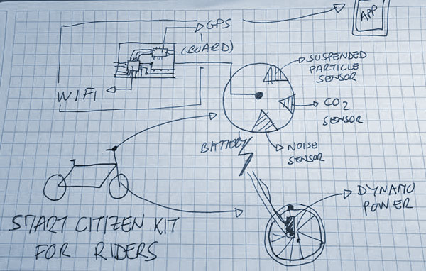
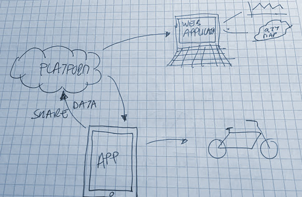
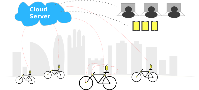
I wish I could resolve the pollution problem but I can't. The goal is to get a map of the city with the pollution level(environmental and noise) in real time. With a web platform or an app, any rider could know the least contaminated route to your destination.
-How-
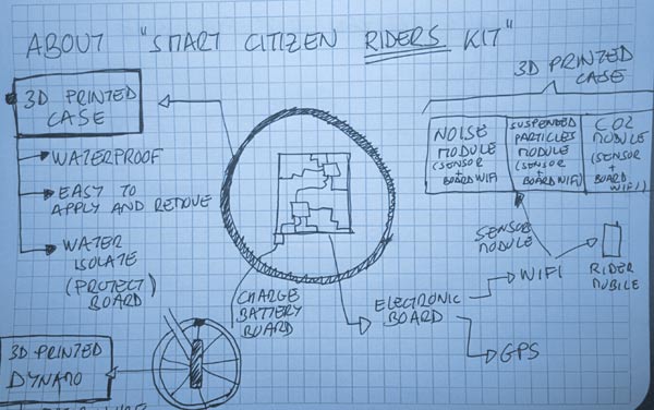
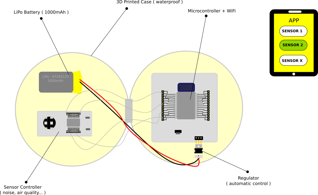
With a "smart citizen kit" device installed in each bicycle. Here some sketchs:
This week began with Neil gaving as an overview of computer-aided design tools and different types of 2D, 2.5D and 3D tools. For more than 10 years I didn't use many of these programs ( except Adobo Photoshop ). So I decided to use one of each type to complete the definition of my final project .
- 2D, 2.5D RASTER -
GIMP
GIMP is a cross-platform image editor available for GNU/Linux, OS X and Windows.It's a great open-source tool for high quality image manipulation and for images optimization.
- 2D, 2.5D VECTOR -
INKSCAPE
Inkscape is an open-source vector graphics editor similar to Adobe Illustrator, Corel Draw, Freehand, or Xara X. What sets Inkscape apart is its use of Scalable Vector Graphics (SVG), an open XML-based W3C standard, as the native format. It's a croos-platform software too.
I have used this tool to complete the definition of my final project: the general idea on a pict
and the hardware I'll need
- 3D DESIGN -
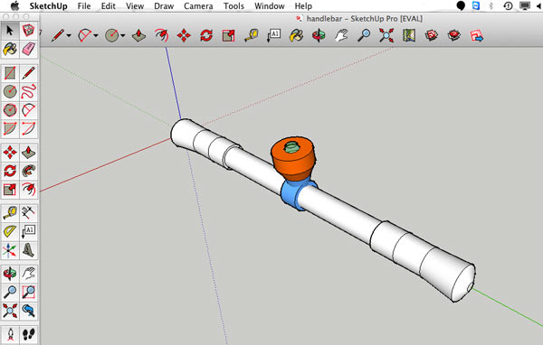
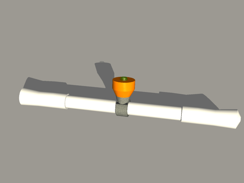
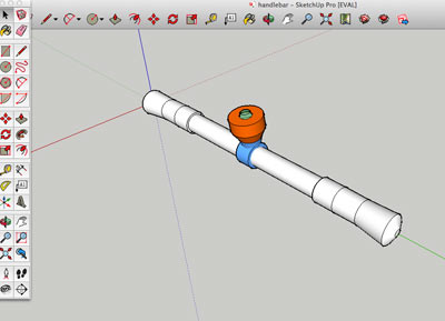
SKETCHUP
Sketchup is a 3D modeling computer program for a wide range of drawing applications such as architectural, interior design, engineering and video game design.
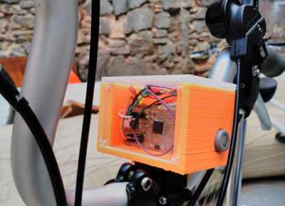
I've used Sketchup for modelling the case for the bike sensors. In that case over the handlebar.
RHINOCEROS
Rhino(ceros) is a commercial 3D computer graphics and computer-aided design (CAD) which geometry is based on the NURBS mathematical model. That model focuses on producing mathematically precise representation of curves and freeform surfaces in computer graphics. Some renders using Rhino:
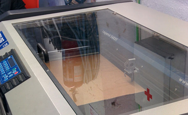
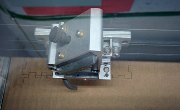
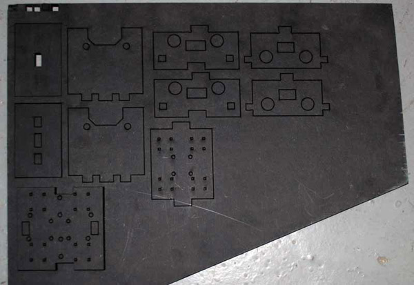
I've made my "press-fit" construction kit using a laser cutting machine and with cardboard as material. First I did was document myself about this technology and understand how it works.
Light Amplification by Stimulated Emission of Radiation
A laser is a device capable of focusing a light beam of high energy [power] in a very specific point in space [precision] for a certain time [speed+frequency].
- LASER CUTTING MACHINE ADVANTAGES -
It does not generate waste or just chip .
It provides improved accuracy and surface finish ( roughness).
Fast and productive machinining
It's possible to create complex shapes with different materials: cardboard, wood or acrylic.
- APPLICATIONS -
We can use the laser machine for marking, engraving,
cutting or burning. Depending on the parameters ( frequency, power and speed ) we use, we get different results.
- LASER CUTTING vs OTHER DIGITAL FABRICATION TECHNOLOGIES -
Laser cutting has a much higher speed than conventional milling machines for one piece.
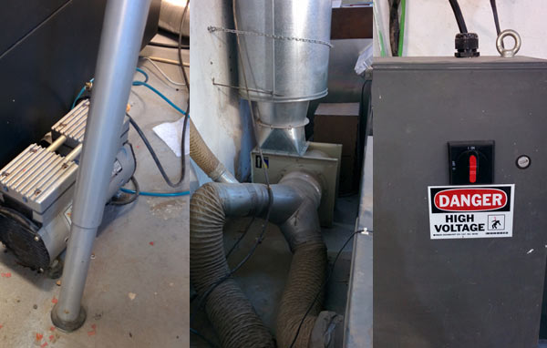
They are quiet machines devoid of large vibrations but require appropriate flue gases emitted by the cutting process. This determines the location for installation.
The price is quite high even for basic models but are becoming cheaper as use of face-to beginners and small manufacturers is generalized . Basic equipment brands such as Epilog or Trotec are around 6000 EUR .
Other aspects to consider when using a laser are the auxiliary equipment required for proper use .
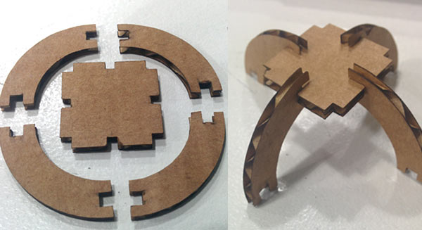
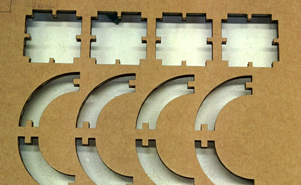
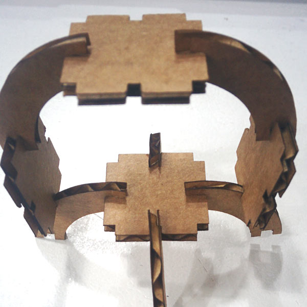
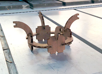
PRESS FIT CONSTRUCTION KIT
A press-fit kit, is a set of shapes that are able to create a construction that stands in place without screws or anything, just by putting one piece into another and pressing them together.
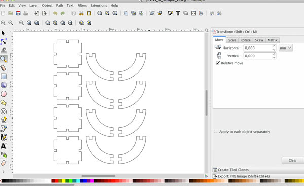
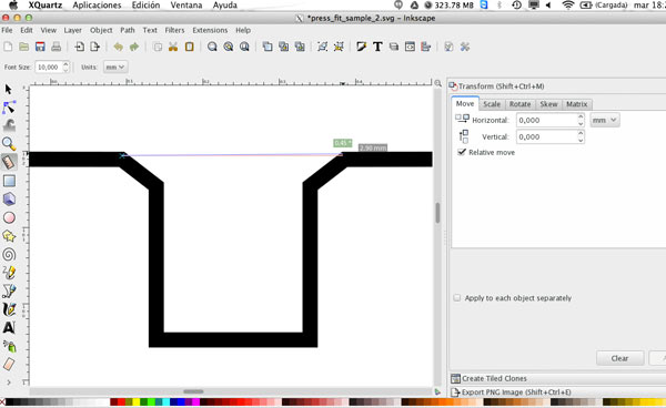
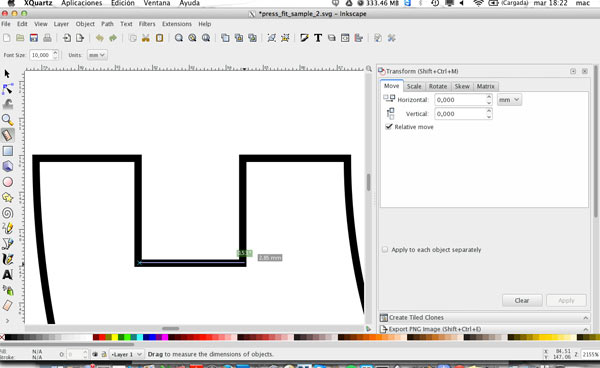
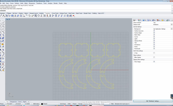
I've decided to design and make a press fit based on two shapes. Designed in Inkscape and Rhinoceros 5.0. It's the step by step process.
SOME LESSONS
The laser follows the center of your vector line (drawing), burning away 0.1 mm on each side of the vector.
Parameters setup before "cutting": speed vs power + frequency. More speed and less power for engraving. Less speed and more power for cutting.
A vinyl cutter is a type of computer controlled machine. Small vinyl cutters look like computer printers.
The vinyl cutter uses a small knife to precisely cut the outline of a picture into a sheet or piece of vinyl. The knife moves side to side and turns, while the vinyl is moved beneath the knife. The results from the cut process is an image cut into the material ( thin self-adhesive plastic ). The material is then 'weeded' where the excess parts of the picture are removed.You can use the vinyl cutter for flexible circuits, stickers or signs depending of the material.
STEP by STEP
Set document units to mm.
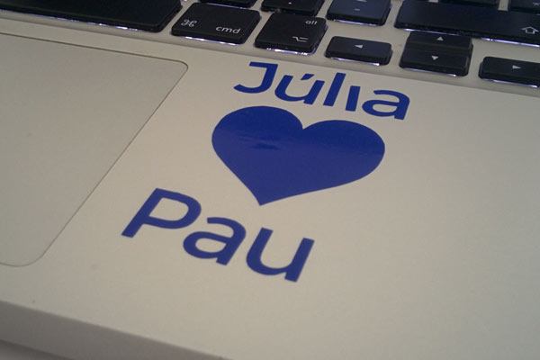
Design the image you want to turn into a sticker. I've used Inkscape and drawn a shape (heart) and letters (my kid's name :)).
Make sure the shapes have an outline.
Save the image as .svg or .png in black & white. Important: Give high resolution to the image.
Put the material in the machine (push up the lever).
Secure the material (push down the lever).
Turn on the machine.
I used Fab Modules so I launch the application: "fab".
Selectd design format (.png) and machine (Roland Vinyl)
Load file .png
If necessary, resize the design.
Press "Make Path" to see how the image will be cut.
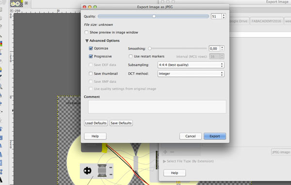
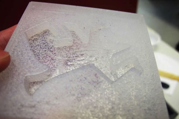
Check if there is any mistake. In my case, first, I exported .png design in a low resolution quality and though I tried to fix it changing some of the parameters of the application (error pixel),it didn't work. I decided to export the design with a better resolution and it was fixed.(see images to compare low and high cutting).
Adjust settings before cutting. Force: 45 g/f, Speed: 2cm/sec.
Press "Make .camm".
Remove material from the machine.
SOME LESSONS
If you import to .png be sure it's black and white.
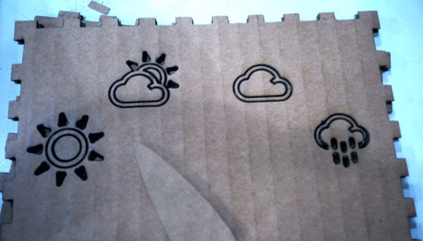
My little boy , Pau (3), is responsible for the forecast in its class at school. Every morning , he asks me about weather forecast. So this week I've designed and made a forecast station in a cardboard box using:
Inkscape + Rhinoceros for press-fit box
Littlebits: 9-volt battery + Power module // Cloubit module ( to connect it to Internet) //Servo module
One of the main reasons because of I joined Fabacademy is for the content of this week. To mill , weld and program my first ISP! ( In-Circuit Programmer ) Perhaps one of the least creative weeks but one in which more I worked with other colleagues , absolutely. The difficulties that (We) I've been finding in each of the steps have been less because of my instructors and classmates. Thanks Ferdi, Santi, Janaki, Arnau, João, Carol, Donato, Citlali, Jisun, Joe, Luiz, Edgar, Norma, Cansu and Elissa !
The assignment for this week is to make a FabISP in-circuit programmer - stuffing the board and soldering the components to it. The FabISP is an in-system programmer for AVR microcontrollers, which is designed for production within the FabLab. It allows you to program the microcontrollers on other boards that we will make in next weeks ( electronic design, embedding programming ).
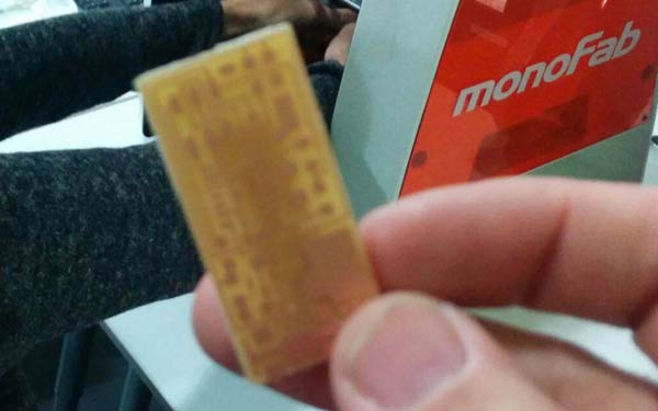
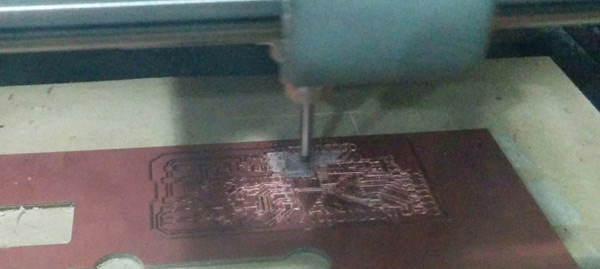
- 1_PCB_MILLING -
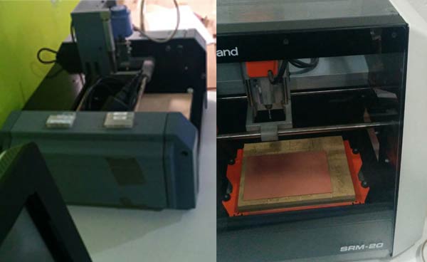
The first step of the assignment is to mill the PCB board. Printed circuit board (PCB) milling is the process of removing areas of copper from a sheet of printed circuit board material to recreate the pads, signal traces and structures according to patterns from a digital circuit board plan known as a layout file. It the Lab, we have a Roland Modela and a Roland SRM-20 which I choose for milling the PCB.
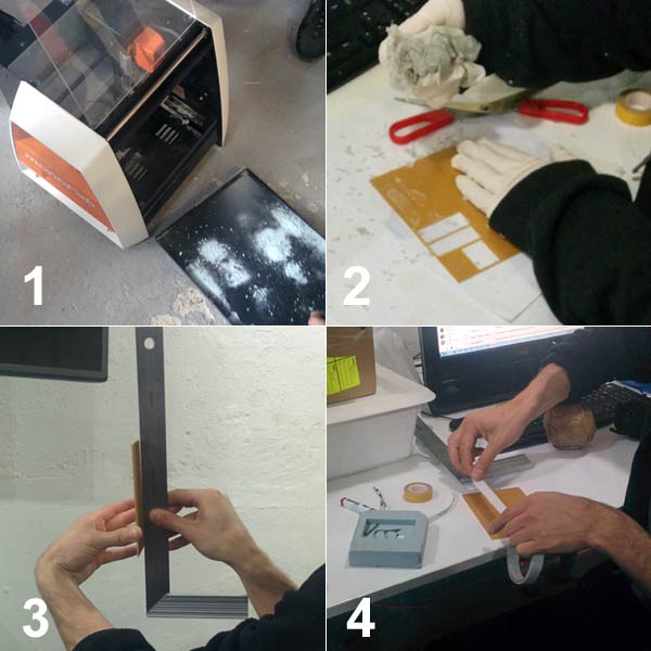
SOME TIPS BEFORE MILLING
Clean the machine. This step should take the most attention and care
If you reuse a sheet as I did, clean it well and remove the double-sided tape. I used acetone to clean and ... patience !
It is very important to make sure that all the surfaces of the boards are flat.
Glue double-sided tape on the bottom of the board and place it on the tray. Ferdi advised us to use a piece of wood to avoid damaging the original tray machine.
DOWLOAND THE BOARD FILES
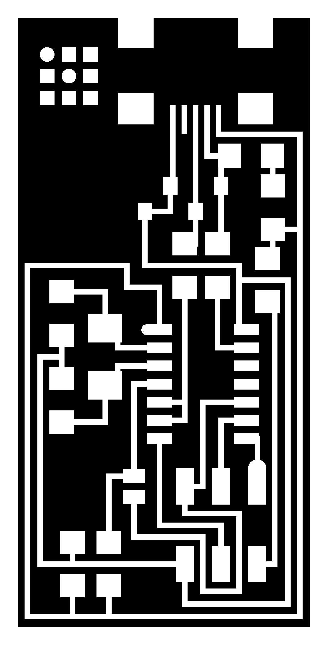
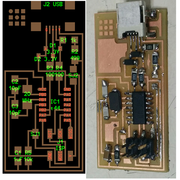
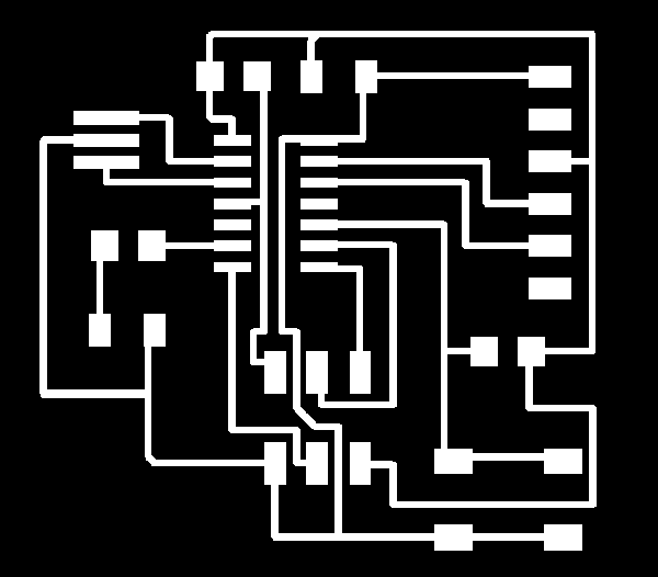
I choose Neil's FabISP so, first, I download .png board files (board outline and traces) into the computer connected to the mill.
FAB MODULES
Fab Modules are a set of software tools for personal fabrication, intended for use with machines common to fab labs.
PNG files (outline and traces) control the paths that the milling machine will use. A fab module converts the .png into paths that the Roland SRM-20 can read.
It's a step by step process for each milling. Be careful with values. Depending on them you can cut ( 1/32 mill ) or engrave ( 1/64 ). First and for testing we are going to engrave the board outlines.
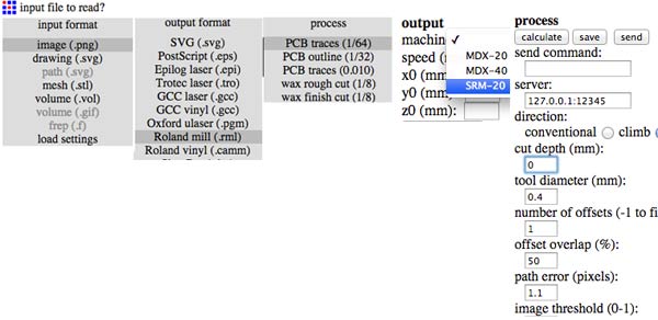
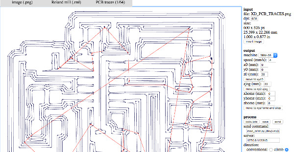
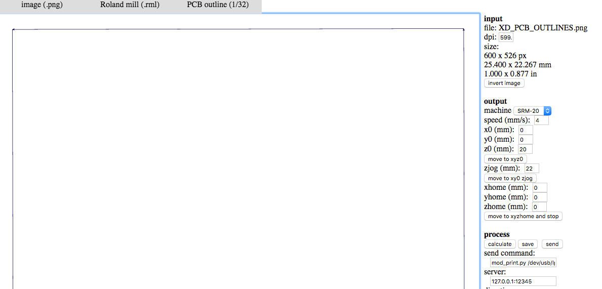
Go to fabmodules.org
Inpunt filte to read: .png and select hello.ISP.44.interior.png
Output format: Roland mill (.rml)
PCB traces: 1/64. For the engraving process we use the 1/64 mill bit.
Right menu: output machine (SRM-20), cut depth 0 mm, number of offsets: 1
Process: CALCULATE !!! Important each time a value of the menu is changed, click on CALCULATE button.
Process: SAVE -> .rml file
MILLING
Check 1/64 mill is placed on then machine.
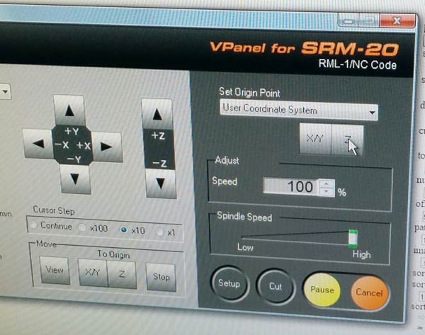
Open VPanel, the Roland software to manipulate the machine.
Move machine tool to your "origin point" using the -X, +X,+Y and -Y buttons. Click on X/Y button.
Finally, move the tool down using the arrows.When the tool is almost touching the copper surface, open the machine and with your hands and the allen key move the tool until it touches the copper. Click on Z button.
Click "Cut" and select the .rml file.
NOTE: You can adjust the "speed" (20%-25% ) at the begining of the process to see how the machine is working, and if there is something wrong, stop the machine.If not, set speed to 100%.
ENGRAVING THE CIRCUITS
Repeat the process before for engraving the circuits but with these values: Loading the circuits .png file (hello.ISP.44.traces.png),1/64 process mill bit__Cut depth:0.1 mm__number of offsets:4.
MAKING THE CUT
IMPORTANT!: Change the mill bit to 1/32.
Repeat the process but with these values: Loading the outlines .png file (hello.ISP.44.interior.png),
1/32 process mill bit__Cut depth:1.6 mm (material itself is 1.5mm)__number of offsets:1.
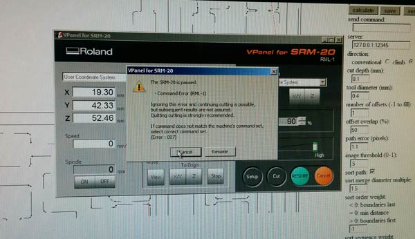
VPanel or FabModules error
At the begining and at the end of each milling process, a window with an error message (always the same) appears. Apparently it doesn't affect the process and clicking this continues. Ferdi suspect is a change in Fabmodules.
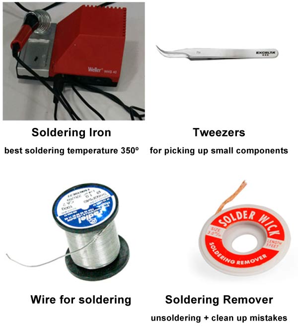
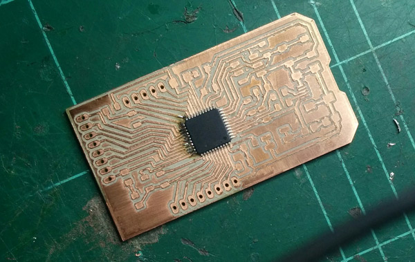
2_SOLDERING
Materials and tools for soldering:
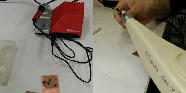
I hadn't previous experience soldering so with Ferdi's help first thing I did was do some tests (soldering / unsoldering) with unusable components. I also watched this tutorial.
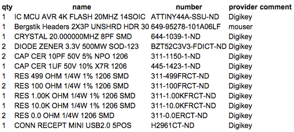
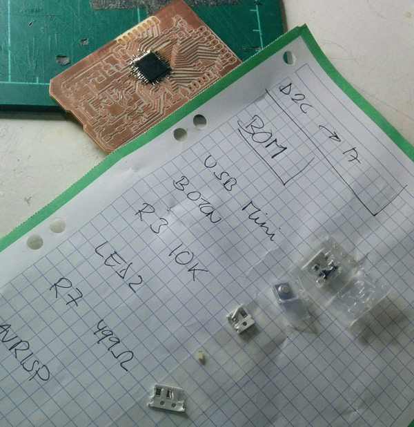
This is the list of components needed to my FabISP. Fortunately ,we already had all at the lab:
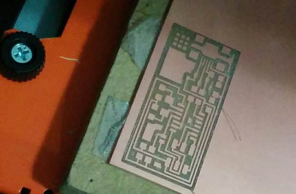
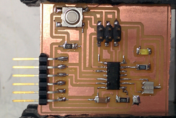
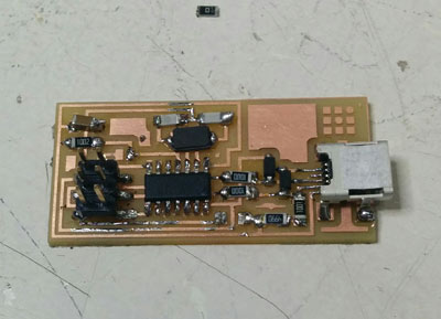
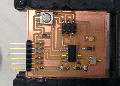
Although it was my first time, soldering was relaxing for me and...slow!( It took me 2 hours and a half). The process I followed was to start with the USB connector, go down and inside out (view schematic). This is the result:
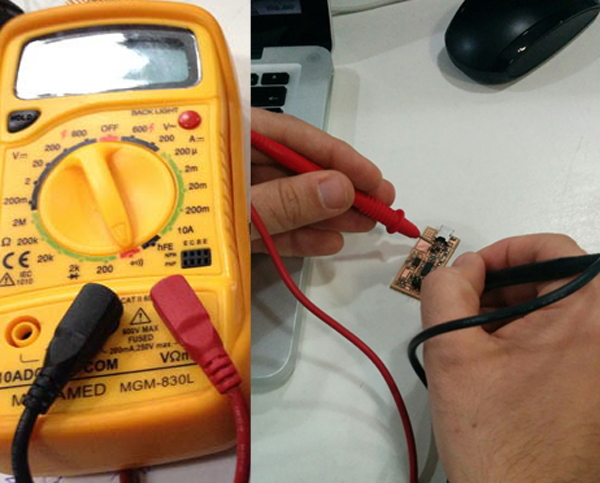
TESTING THE BOARD CONNECTIVITY
Before connecting the board to the computer, it's very important to check the connectivity of the components. I used the multimeter and the schematic image as reference and everything was correct.
3_PROGRAMMING
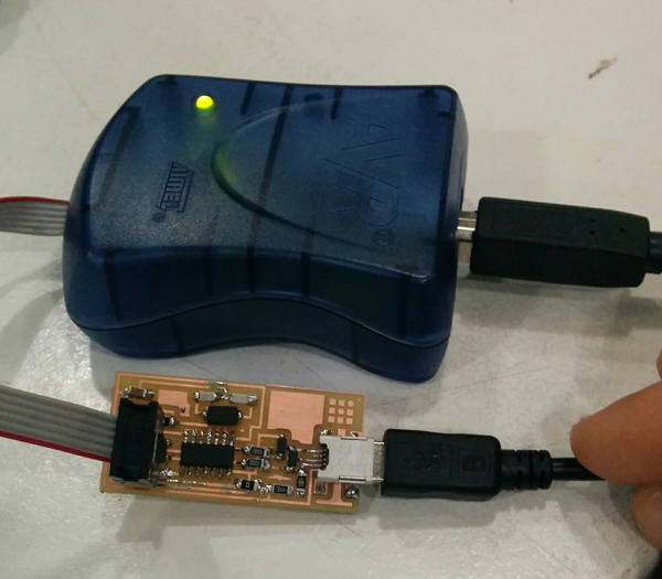
To Program the ISP I followed each step of this tutorial.
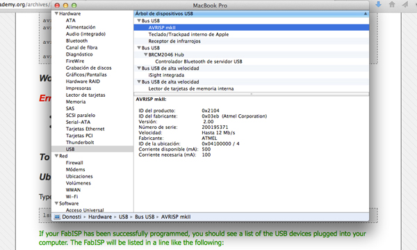
I used AVR programmer. First, I connected the programmer to the 6-pin programming header on the FabISP board and got GREEN LIGHT! It means that the header is soldered correctly and the board is getting power.
Last step was to program the board. I'm using OS X Lion (10.7.5) with the necessary software tools.
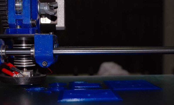
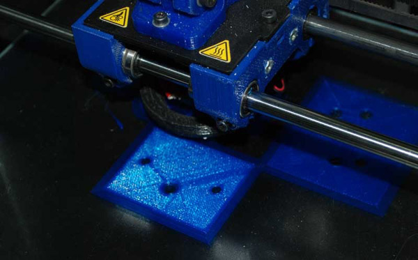
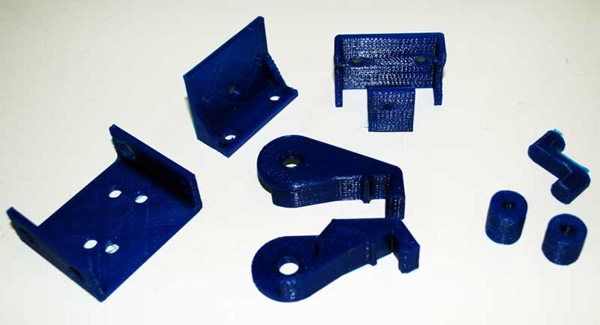
Additive manufacturing processes (or 3D printing) create objects by fusing layers of material together. Subtractive manufacturing, such as CNC milling and turning, uses a block of material and removes unnecessary excess until only the desired shape remains.
Which one is better? Depends on the needs and features of the prototype to print. After a quick investigation into articles and videos I've designed this grid to choose which process is better in any case:
Excepting the second week of FabAcademy, I hadn't worked with 3D software since 10 years ago. So I've used this week assignment to updated me. I've chosen Blender as 3D software tool for this week and I've made some tutorials ( Ferdi's Blender workshop and Creating a model for a 3D printer with Blender).
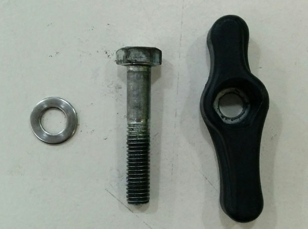
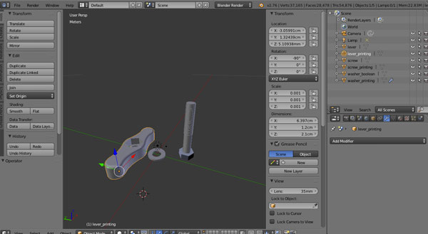
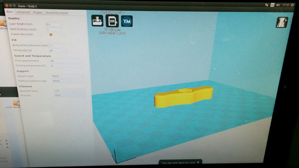
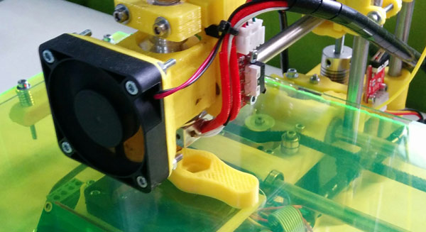
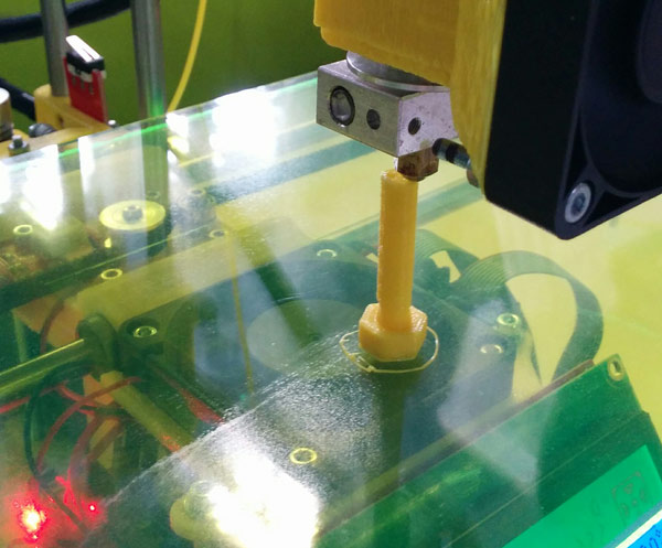
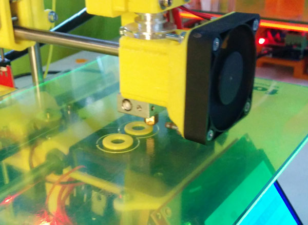
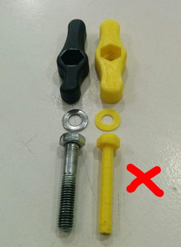
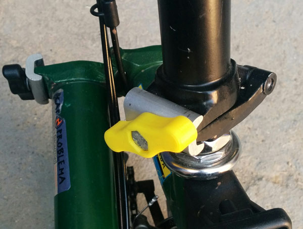
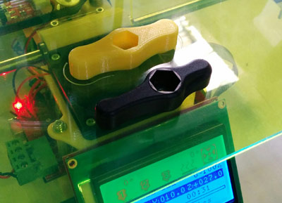
Once I felt more comfortable with Blender I decided to design something that was useful to me and I could also test the capabilities of the 3D printer ( Formbytes ):a screw, a lever and a washer (some parts of my Brompton bike).
I used a caliper to measeure the original objects. In Blender, I used some primitives, edit tools and some modifiers ( bevel, screw and boolean ) for designing.
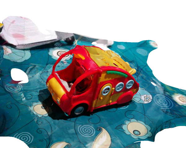
123D Catch is a free app (AUTODESK) that lets you create 3D scans of any object. It generate a 3D model from photos.
For this example I've used my son's favorite toy van :).
SCANNING PROCESS
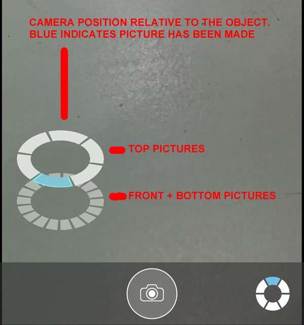
The first step is to take a number of pictures (they recommends between 20 and 40) of your object, so that 123D Catch can assemble a 3D model.
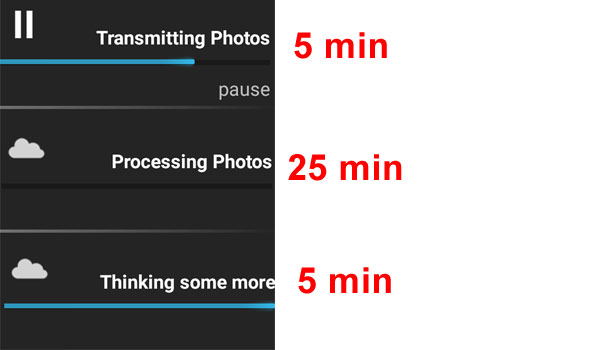
Send pictures for processing...and wait!
One the process is finished, you can export and download it: .stl, .obj ( with textures ) and edit with Meshmixer.
TIPS FOR 123D Catch
Photographs should capture all sides of the target object, both all the way around, and top and bottom. User interface helps you to choose the right position to make the photo.
The object should not be moved at all during capture, and lighting should remain consistent. In effect, once the object is in place, you should move around. it
The target object should take up most of the frame: either get close to the object or zoom in.
While it is not absolutely necessary to maintain the same distance from the object all the way around, it does help the algorithm if distances are consistent.
Consistent diffuse lighting all around the object works best.
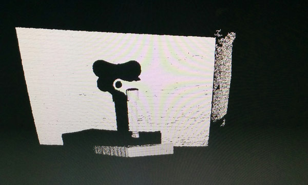
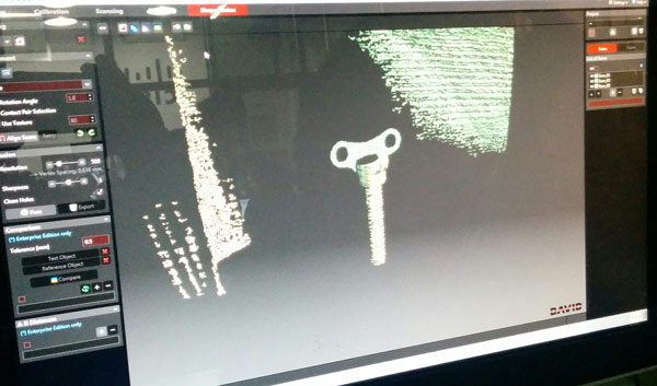
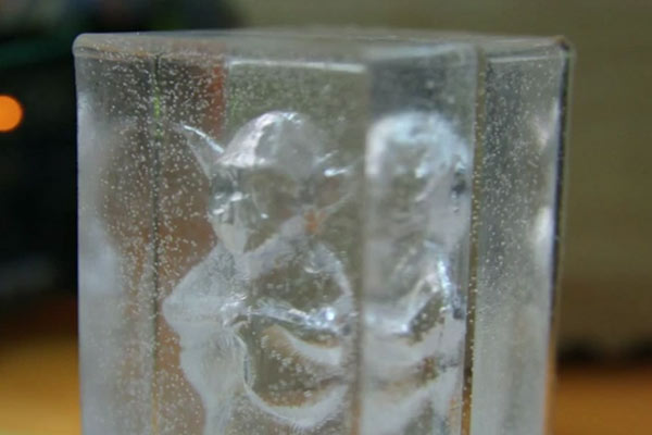
DAVID 3D SCANNER
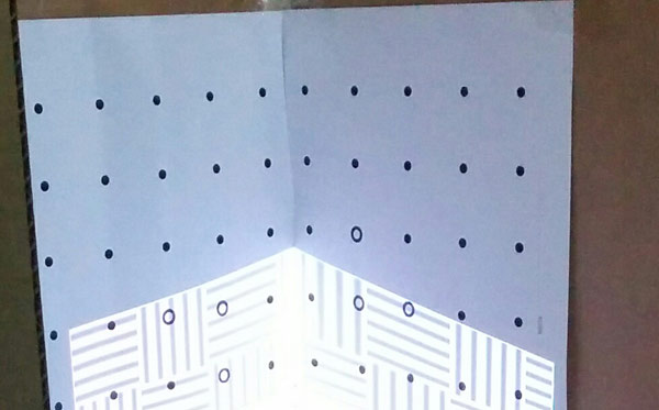
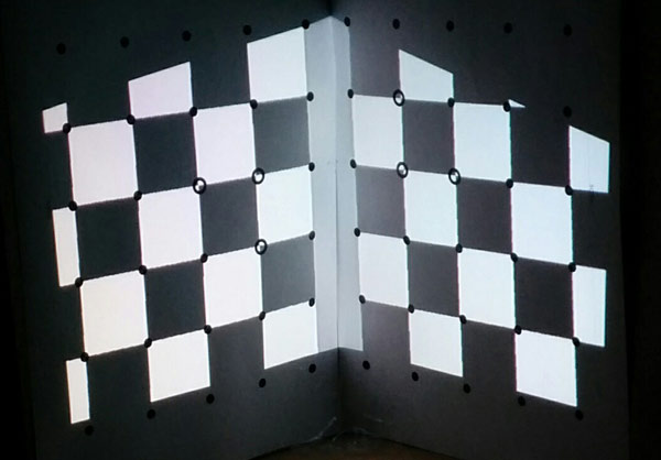
Cit, Arnau, Elissa and me experienced with David Laserscanner Software, trying to scan a simply object. This software is based on light and allows scanning and digitizing of three-dimensional objects using a camera, a laser ( a projector in our case) and two plain boards in the background.
SCANNING PROCESS
Prepare environment for scanning: * Two boards:vertical planes positioned at 90 degrees to one another behind the object to be scanned with the calibrations printed sheet glued. We did it with cardboard.
* Camera:At first, we used a webcam but we could not calibrate because of its low quality.So we changed it to a better cam (Canon) that Ferdi left us.
* Pico projector NOTE: Turn off the lights!
An initial calibration is made to determine the lens parameters and location of the camera relative to the background boards.
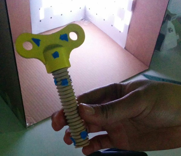
Mark with points the object to scann
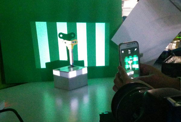
Start scanning: It is important scanning each part of the object : left, right, front, back
It was the result:
CONCLUSIONS
It's for small objects with not complex shapes.
The result can change depends on the environment conditions. ( light, camera quality... )
I have no previous experience in circuit design and very little in electronics so the first thing I've done is to understand the function of the different components and read some information about electronic design tools.
COMPONENTS
Microcontroller is a small computer (SoC) on a single integrated circuit containing a processor core, memory, and programmable input/output peripherals. Microcontrollers are used in automatically controlled products and devices (embedded systems). For this assignment I use Attiny44: Low-power Atmel 8-bit AVR RISC-based microcontroller.
FTDI cable is a USB to Serial (TTL level) converter which allows for a simple way to connect TTL interface devices to USB. The I/O pins of this FTDI cable are configured to operate at 5V. One side is a USB connector and the other is terminated with a 0.1" pitch, 6-pin connector with the following pinout: RTS, RX, TX, 5V, CTS, GND (RTS is the green cable and GND is black). My design has a FTDI-SMD-HEADER.
Resistor is an electrical component that limits or regulates the flow of electrical current in an electronic circuit.
Ohm's law: in a direct-current (DC) circuit, the current through a resistor is inversely proportional to its resistance, and directly proportional to the voltage across it. R (Ohms) = E (voltage)/I(amperes)
LED(light-emitting diode) is a semiconductor device that emits visible light when an electric current passes through it.
Button (or switch) is an electrical component that can break an electrical circuit, interrupting the current or diverting it from one conductor to another.
TUTORIALS
Before redraw the echo hello-world I did this Eagle Tutorial.
Also I followed this assignment tutorial that helped me for doing the assignment.
SETTING UP EAGLE
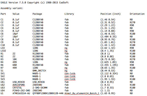
First, download and install Eagle. I use Eagle 7.5 as a freeware.
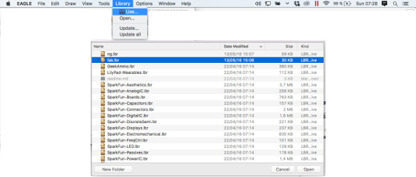
If you want to use components from the FabLab inventory, it is necessary to add the FAB LAB EAGLE LIBRARY to Eagle: In MACOS its in the Applications/Eagle/lbr folder.
To use a library in Eagle: Menu Library->Use and select your favourite library.
Finally it's important to understand the two parts of an electronic design in Eagle: 1. Schematic Design
The schematic editor allows you to create a symbolic easy-to-read representation of your design. The goal of the schematic is to provide documentation about the design, allowing others to easily understand your design intent.
2. Board Layers Design
It’s here where the dimensions of the board come together, parts are arranged, and connected by copper traces. In the board editor, the conceptual, idealized schematic you’ve designed becomes a precisely dimensioned and routed PCB.
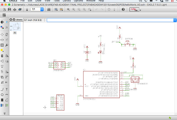
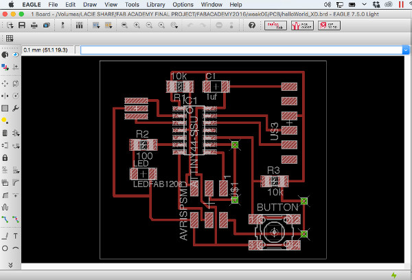
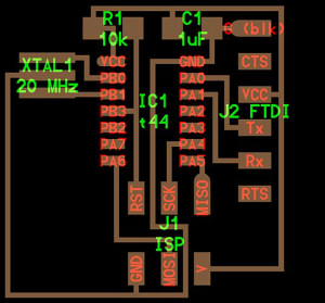
1_REDRAW THE ECHO HELLO-WORLD BOARD
First, open Eagle and create a NEW PROJECT.
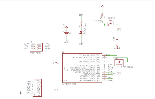
Taking Neil's design as a reference (above image) we need to identify, understand and add the components to the schematic design.
IDENTIFY COMPONENTS
1. Microprocessor: Attiny 44 SSU (IC1 t44)
2. FTDI 6 head (J2 FTDI)
3. Ceramic capacitor 1uF (C1 1uF)
4. Resistor 10K (R1 10K)
5. Resonator 20Mhz (XTAL1 20Mhz)
6. AVRISP 2x03 SMD 6 head (J1 ISP)
Also I added:
7. Switch Button
8. Resistor 10K Ohms for the switch button (R3 10K in my design)
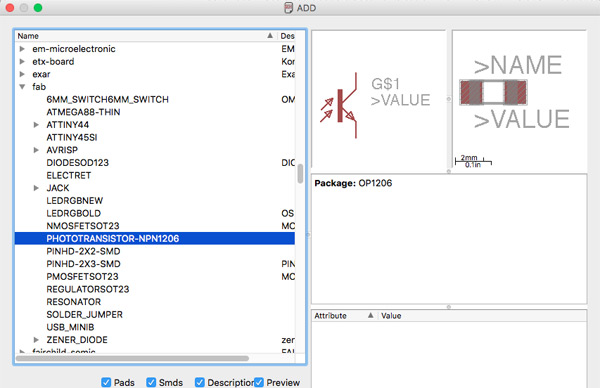
9. LED 1206 (LEDFAB1206 in my design)(*)
10. Resistor 100 Ohms for the LED (R2 100 in my design)
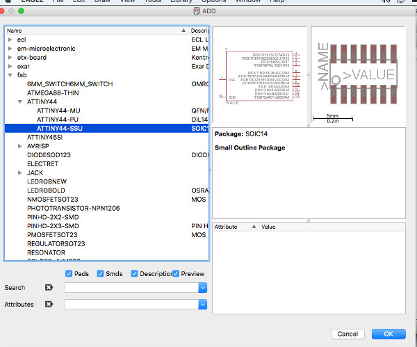
ADDING AND CONNECTING COMPONENTS - SCHEMATIC DESIGN
On the left tool bar: ADD
Search the component ( or select a library) and OK. Most components I need are in the FAB library.
Important: Add Voltage (Vcc) and Ground (GND).
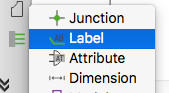
Once you have added the components your need to connect them. There are 2 options to do it:
1. On left toolbar: NET (draw an electrical connection )
2. Adding LABELS (on left toolbar). Components with a same LABEL in the net will be connected. NOTE:Be sure that the connections between the components is correct.
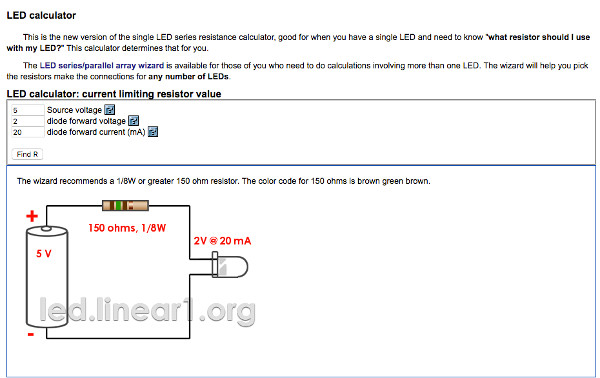
What resistance use?
Ferdi recommend us use this online resistance calculator. Use at least a resistor with this value.
The larger the resistance value will emit less light the LED.
My final schematic
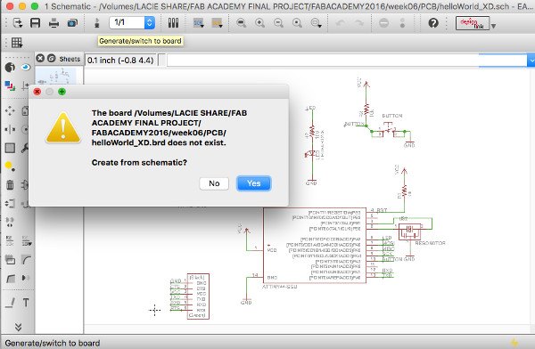
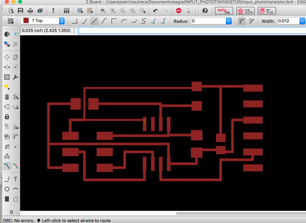
BOARD DESIGN
Second part of the PCB design. In top Eagle icon-menu switch to board
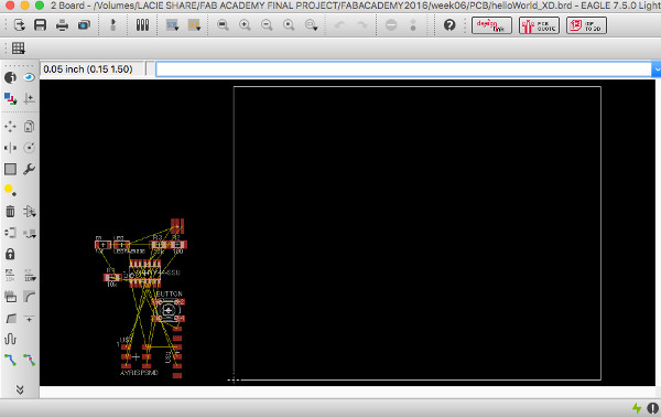
Eagle generates the traces between components automatically but you have to make the routes. Note:You can use commands in Eagle. Here there is a list of the most useful. Step by Step
1. Place the components inside the white square. You can use the white square as a reference of the board dimension. As it was my first PCB design I use Neil design as a reference.
On the Eagle left tool-menu you can find all you need to place the components and optimize the design: rotate, delete, move, move by groups, properties, route manually, delete routes...
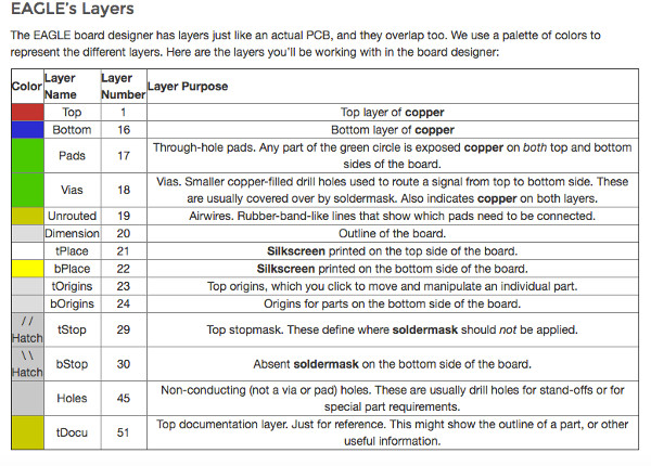
Also you can define holes or vias in your PCB design. Eagle works with layers and it's important to know what you can find in each one:
2. Tracing. Manual routing is done with the Route command.You can also let the Autorouter do the routing. After working with Eagle I prefer do manual routing because you have more control on the design. It's important to do a good tracing because it will avoid many problems in the milling and soldering process.There are different tool options to make things easier.
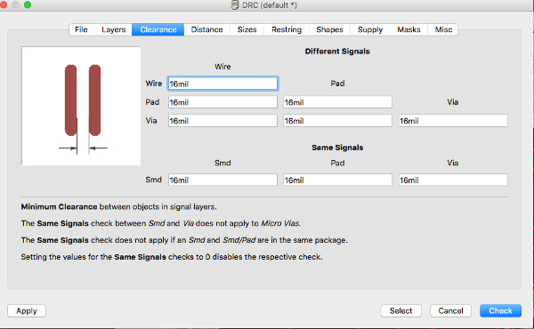
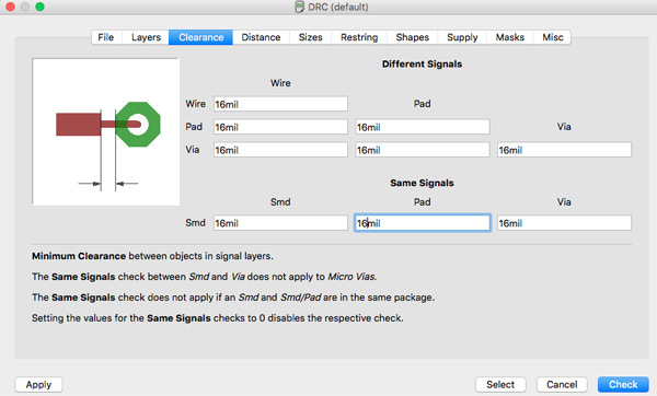
3. Design Rules Check (DRC). The command DRC checks a board against the current set of Design Rules. Design Rules define all the parameters that the board layout has to follow.
The Design Rules of a board can be modified through the Design Rules dialog, which appears if the DRC command is selected.
Ferdi recommend us to use in the Clearance Tab 16 mil.
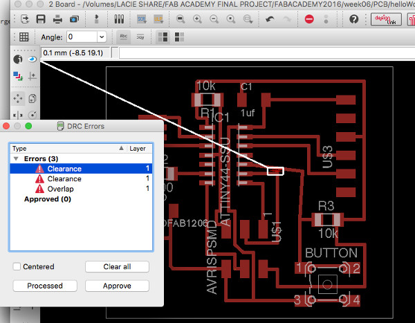
I made some mistakes in the tracing as you can see in the next image.
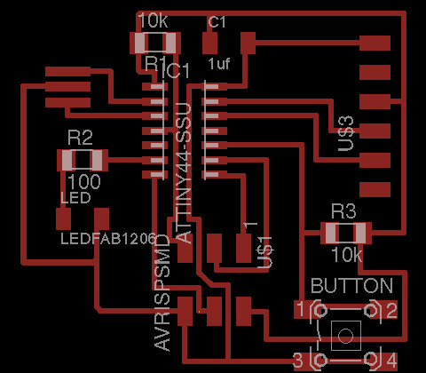
After redesing some traces I fixed all errors. Final Board
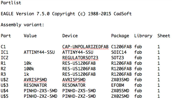
BOM PCB board
4. Export boards files to be milled.
In the Eagle menu File->Export->Image IMPORTANT:Files has to be .png and monochrome with more than 400 dpi (I use 600 dpi).
I export TRACES file. I do the OUTLINES with Gimp. TIP: Use Eagle layers menu to hide all layers less top layer(for the traces).
MAKING THE BOARD
In the Fab Modules:
1. For the TRACES:1/64,X=0,Y=0,Z=20(to avoid fabmodules bug),SRM-20, cut depth 0.1,offsets 4
2. For the OUTLINES:1/32,X=0,Y=0,Z=20(to avoid fabmodules bug),SRM-20, cut depth 0.6,offsets 1, stock thickness 1.7
3. Calculate .RML files.
4. Open VPanel
5. Define X/Y Origin Point
6. Define Z Origin Point
7. Change tool mill (1/64 for traces and 1/32 for outlines)
8. Setup->Select .rml file (first traces and second outlines)
9. Cut
10. Clean the board
11. Print list of components
12. Soldering the components
13.TEST the connections with the tester tool
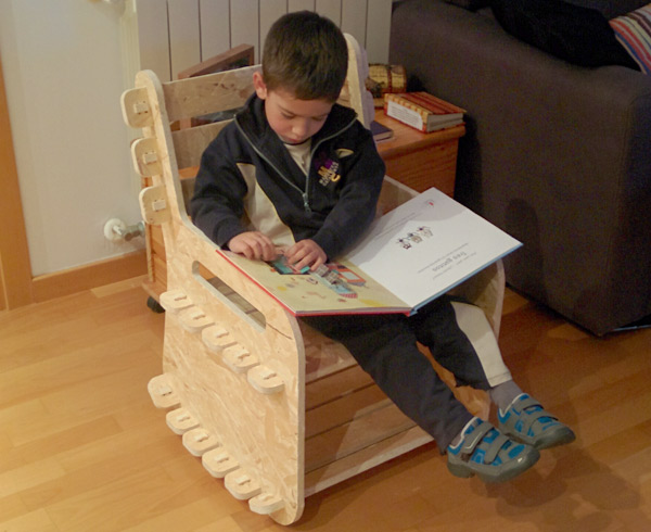
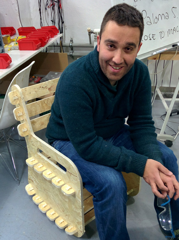
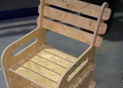
The assignment for this week is to design and make something BIG (whithout nails or glue) ! But what ? All the people who make FabAcademy sacrifice part of our lives to do it. In my case, it's to give up spending time with my kids (Pau[4] and Júlia[7]). So for this week, I've decided to make something for them, something BIG and useful: a chair where they can spend time reading tales, comics....
0_INTRODUCTION
Material
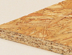
For making the chair I have an OSB wood sheet of 2500mm (length) x 1250mm (width) x 15mm (thickness). Our partner is Gabarró. OSB (Oriented Strand Board) is a type of engineered lumber similar to particle board formed by adding adhesives and then compressing layers of wood strands (flakes) in specific orientations.
Software
At first I used SketchChair. It's an open-source software tool that allows anyone to easily design and build their own digitally fabricated furniture in only a few steps. I've installed and tried but after do some sketchs I've decided not to design my chair with it because: It's a beta version and has some bugs (I've used v.9.0.1) and also, I haven't control in the design (dimensions, shapes, details..).
So, although I've never used it, I've chosen SOLIDWORKS. It's a professional and commercial 3D CAD design software.
If it's your first time in Solidworks I recommend you this tutorial compilation from youtube.
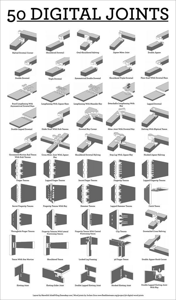
Joints
One of the requirements for this assignment is to make the (BIG) object without using nails or glue. So, before designing anything, is important to search for wood joints references and decide which one you'll use.
Some of them:
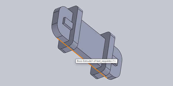
1_DESIGNING A CHAIR IN SOLID WORKS
The design of the chair is quite simple but effective. It's divided in 3 parts and if you want to desing it, first draw the shape of each part and then extrude it. [My tips]
- Extrude each shape in Solidworks with the thickness of your wood sheet.
- Think which joint are you gonne use.
- Do the holes of the join 0.5 mm smaller than the piece.This will fit better and better grip.
- IMPORTANT!: Make a joint test, mill it and check if it works before making the BIG piece.
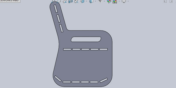
"PAUCHAIR" parts: Two sides with armrests incorporated into the same pieces. Designed with holes for the back and seat pieces.
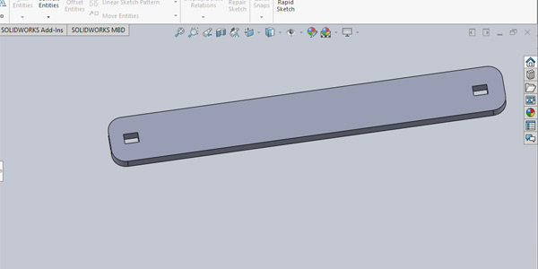
Back and seat pieces. Also, I use these pieces to keep books and stories at the bottom part of the chair.
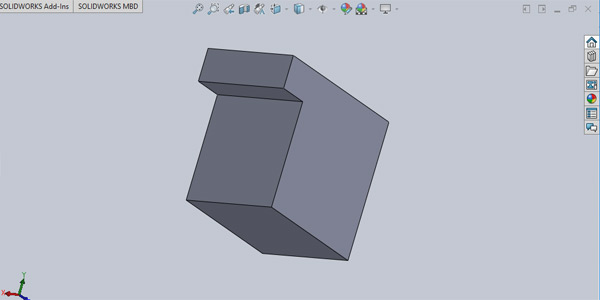
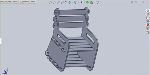
Lock piece that prevents the chair disassembles. The final model
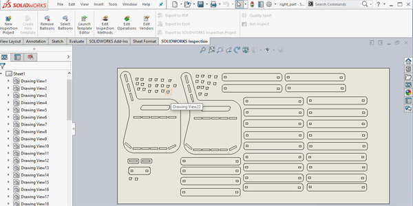
2_EXPORT TO DXF
Before prepare the files for the CNC machine, you need to export the 3D model to a .dxf file with ALL the pieces you need. In SolidWorks, File->Make Drawing from Assembly. Save it as .dxf file.
Tip:When place the pieces, position them for cutting in the same direction.
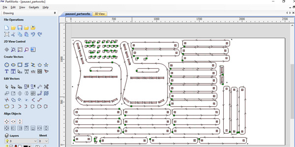
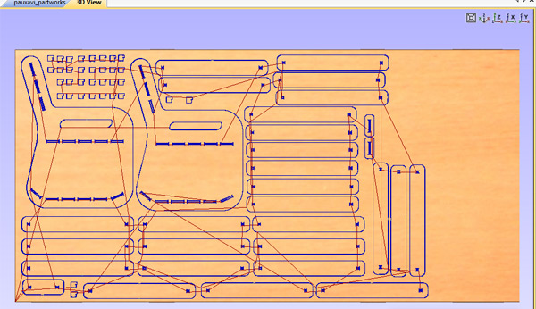
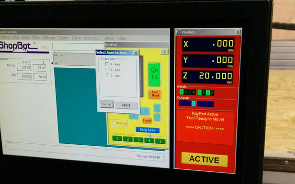
3_PART WORKS - VCARVE
We have in the lab a ShopBot CNC Machine and the software I've used to generate the gcode files is PartWorks-VCarve. There are some other tools like: HSM Works the CAM solution for Solidworks or GCodeTools a plugin for Inkscape.
Step by step in VCarve:
1. Size of the sheet ( 2500mm x 1250mm in my case)
2. Define thickness material (16mm). I added 1 mm more because of the sheet is not flat.
3. Define Z-zero. It could be defined at the top of the material or in the cnc machine base.
4. Define de X,Y zero.
5. Open .dxf file.
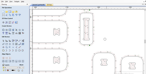
6. Check if all geometry is connected. If not, select all geometry and "joint vectors" ( t-bone fillet).
7. Select CNC mill radius.
8. Add clamps (machine-> table clamps). It will fix wood sheet to the machine.
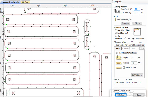
9. Select toolpath
10. Select drill (tooldatabse->tool list, in my case EndMill 6mm).
11. Cutting parameters.
12. Feeds and speeds: Ferdi recommended me: spindle speed(12000 rpm), feed rate 40 mm/s, Plugin Rate (20).
13. Save toolpath and Calculate.
Note: Repeat steps (6-13) for each part depending of the final result you want.
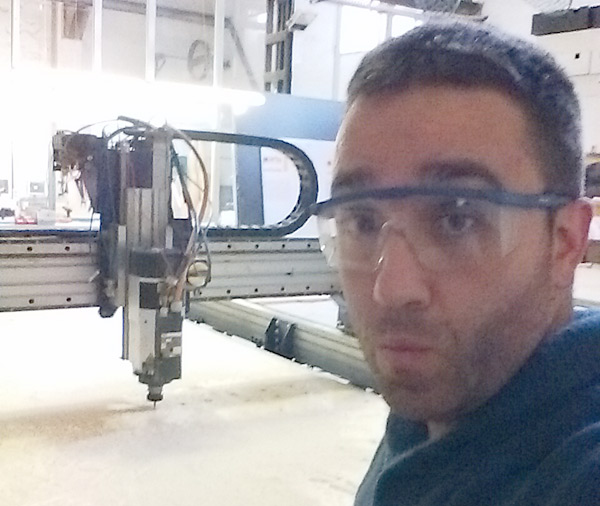
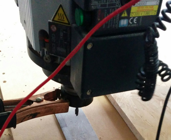
4_CNC Machine
Now, it's time to mill! IMPORTANT: Follow safety measures!
Step by step in ShopBot CNC machine:
0. Place the wood sheet in the machine and fix it.
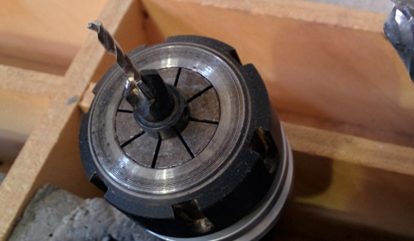
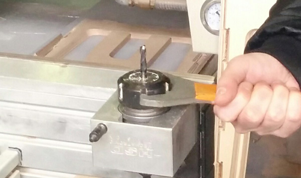
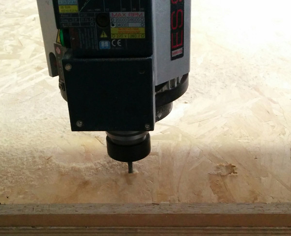
1. Select and fix the tool mill.
2. Setup the machine and the 0,0.
3. Go!
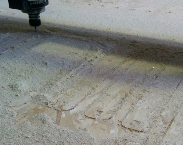
Note: It's important to keep clean the machine area.
5_Result
Once the cnc machine is finished, sand each piece and mount the structure.
CONCLUSIONS
Test the joints! I did it and I avoid many problems!
Make something BIG is a large process! although the object is very simple.
Know material properties is an advantatge for a better design.
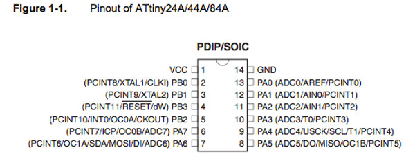
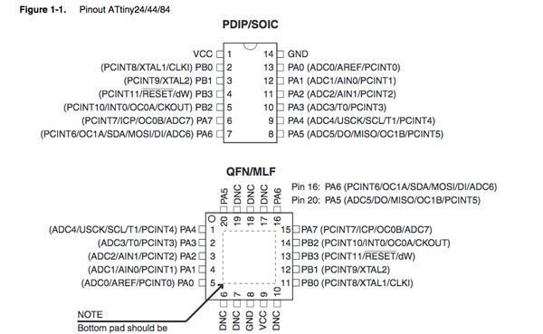
It has been first time I've read a microcontroller data sheet (ATtiny44A).
I will not deny that at first I found it impossible to get past the first page. It was like a hieroglyph for me.
But after much patience and insistence deciphered some things: 1. Pin CONFIGURATION
Good to know how to design a board and in which microcontroller pin connect the components. 2. RESET PIN
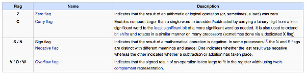
Where the CAPACITOR is connected.I know it's simple but I had no idea. 3. STATUS REGISTER
Are a list of flags bits for a microcontroller. I don't understand it from the datasheet but I read it there and find a better explanation in wikipedia
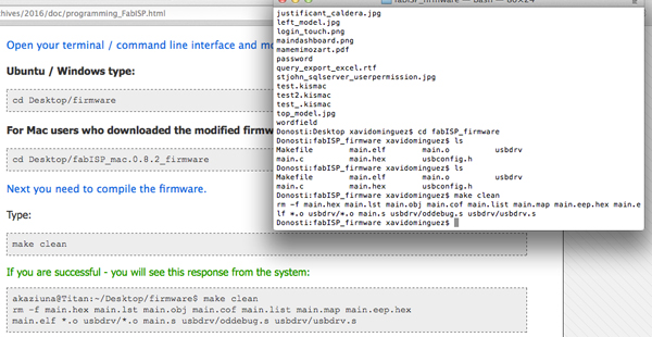
1_PROGRAM THE BOARD WITH DIFFERENT PROGRAMMING LANGUAGES
PROGRAM WITH C
Last time I programmed in C language was while studying engineering in the university...16 years ago...so...this week was good: 1. Ferdi's asssignment 2. Do some exercise of this page 3. Do this FabAcademy tutorial: Makefile for Embedded Programming Step by Step
1. Install GCC compiler. GNU Compiler Collection (GCC) is a compiler system produced by the GNU Project supporting various programming languages, included C of course. I already had it installed in my mac. If it's your first time, you can download.
2. Install AVR Libc.
The AVR Libc package provides a subset of the standard C library for Atmel AVR 8-bit RISC microcontrollers.ATtiny 44 is a 8-bit microcontroller.
I followed this guide.
3. Start coding
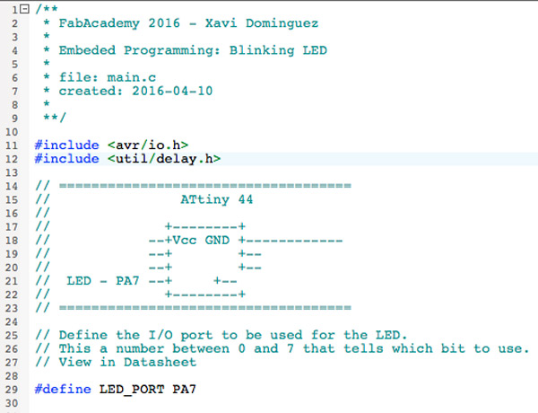
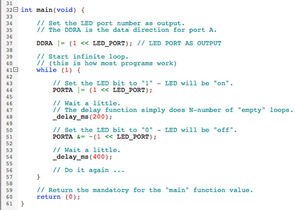
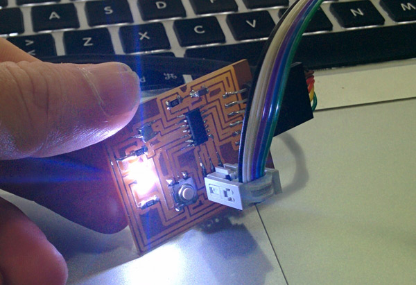
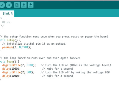
I did a "blink" example. So the idea is to blink the LED I added in the electronics design assignment.
This is the code I wrote based on Neil's example:
The avr/io.h is used for controlling I/O ports on an AVR microcontroller.
If your want to know more about ports on AVR read the datasheet or this great tutorial.
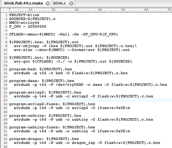
4. Understand Makefile and Make.
First 4 lines are for configuring the Makefile:
a. Name of the file to compile: blink.
b. Extension of the file to compile: .c -> Remember you can use gcc with other languages.
c. Microcontroller to program: attiny44
d. Frequency of the board to program: 20000000 -> Frequency of the resonator I used in the electonic design of my board.
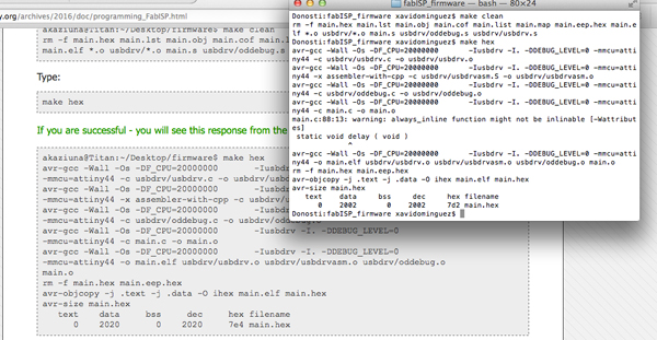
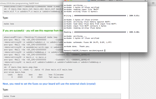
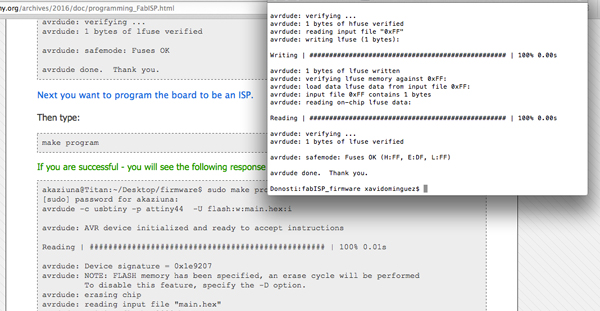
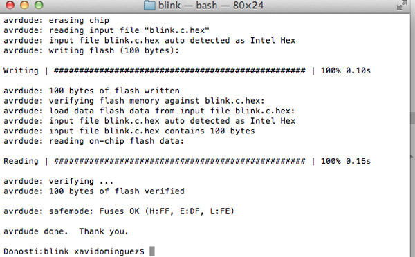
5. Make
sudo make -f blink.ftdi.44.c.make program-usbtiny
Note: Connect your ISP Programm board.
And if everything goes well...
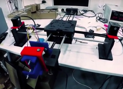
The assignment for this week is to design and make a MACHINE...in group!!!! It is not easy teamwork and less when you do not know at all to the people who are ... but these have been 2 awesome weeks.
I've enjoyed and learned a lot from my teammates:João Leão, Arnau Tàsies, Katerina Labrou and Joe Galea. I hope that they have learnt from me too.
0_INTRODUCTION
Between our group we made a brainstorm of possible machines we could build and the degree of axis freedom we would like to work with.
We ended deciding we would build a circuit drawing bot for kids and grownups. This was a great starting point and so we decided to divide our project into smaller and more manageable tasks : Xavi Dominguez - Programming
Arnau Tàsies - Vector Design / 3D Modelling
Joe Galea - 3D Modelling / Machine Extruder
João Leão - Electronics / 3D Modelling
Katerina Labrou - 3D Modeling / Programming
Although we decided to divide the tasks we wanted to switch between each other so we could have an idea of the different work flows.
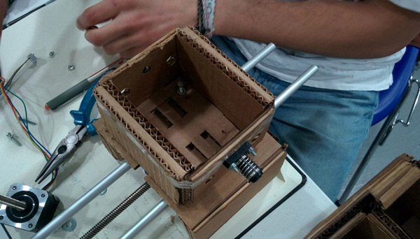
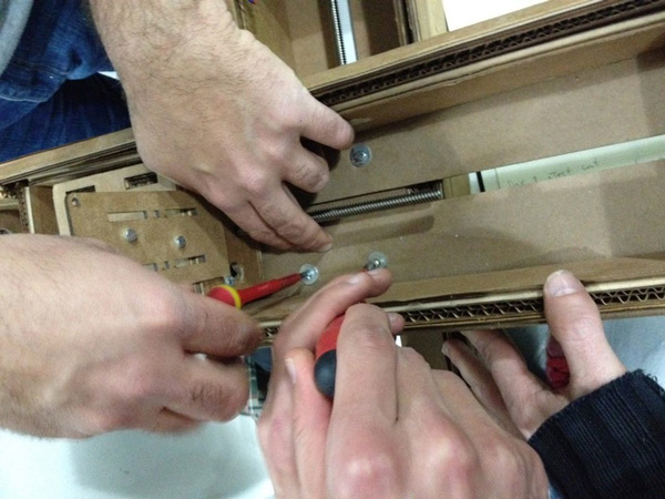
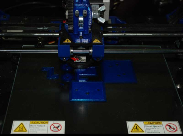
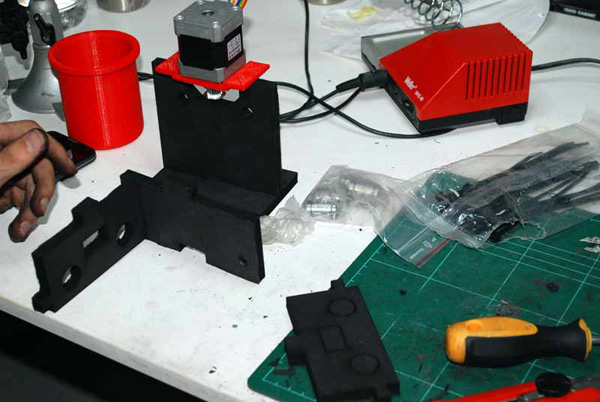
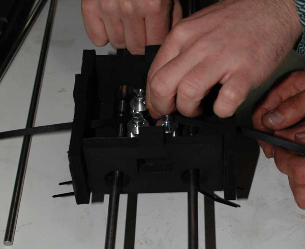
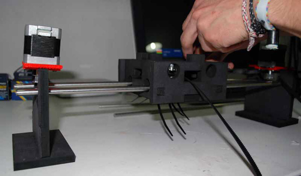
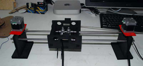
We are going to start by working in the given MTM Kits from Nadya and create a prototype of our desired goal so we can understand how the Nodes, Mechanics and Programming works. As soon as the prototype is well on it's way we are going start designing the Drawbot 2.0 and its mechanics.
My main work in the group has been to understand the mechanics of the machine, programming it and make it work as we want. I've also tried to help my teammates in their tasks besides contributing my experience in teamwork .
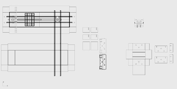
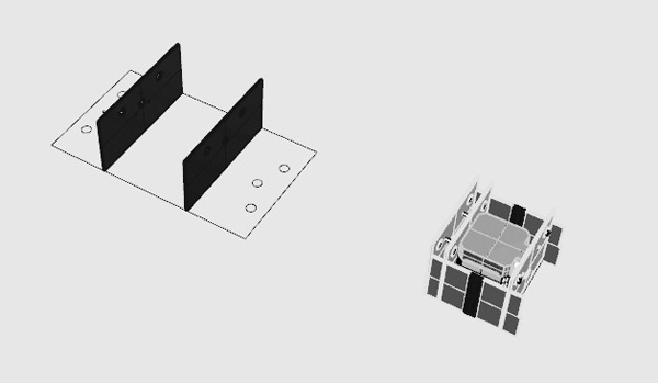
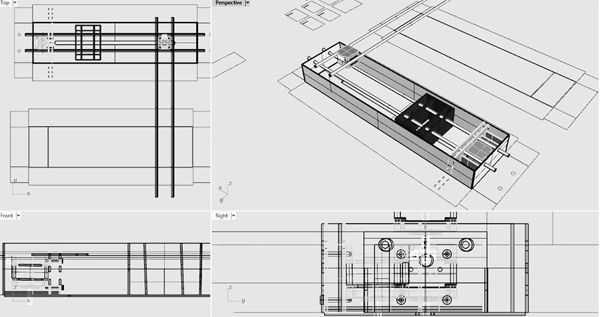
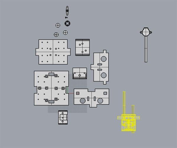
1_DESIGN PROCESS: SOLIDWORKS AND RHINO
Prototyping
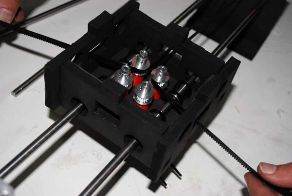
We had a some of the cardboard modules from last year and so we starteded by using them as a means to create a fast prototype of what we wanted our machine to do.
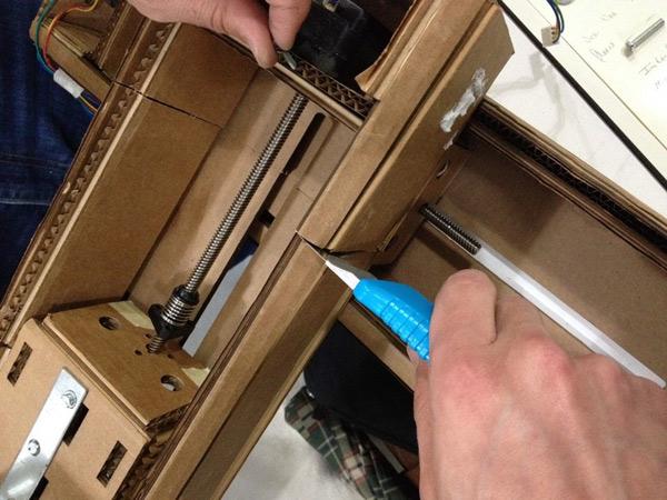
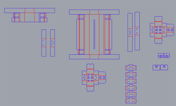
Then,we made the design changes to the original Rhino files with the changes we made to the fast prototype and laser cut it.
As a starting point, we used the Rhino design files from Francesca Perona, you can download them here.
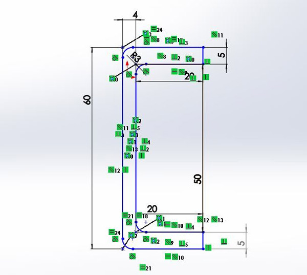
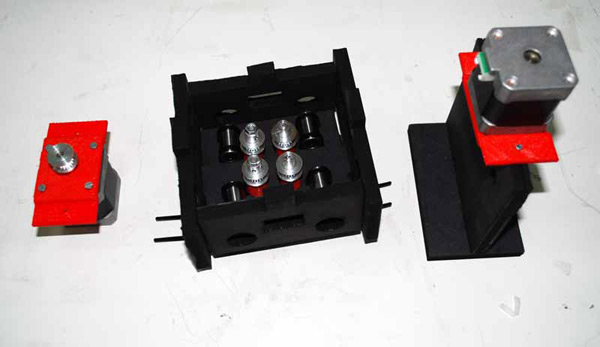
We intended to make the housing of the x,y axis lighter, adapt it to the 2mm cardboard we would use, and correct some details - such as the heights and sizes of the holes for the shafts and the screws.
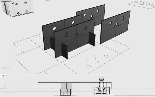
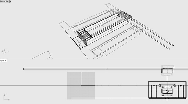
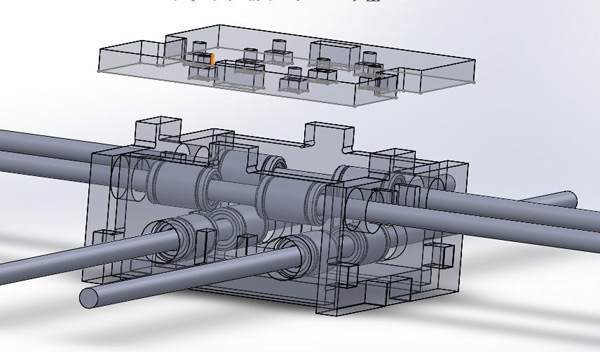
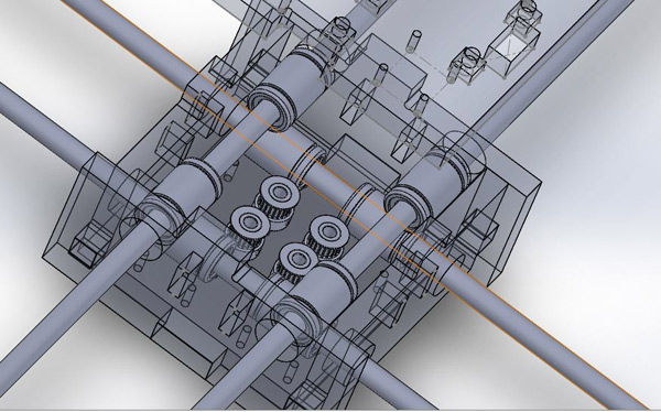
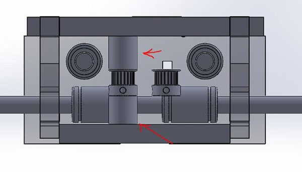
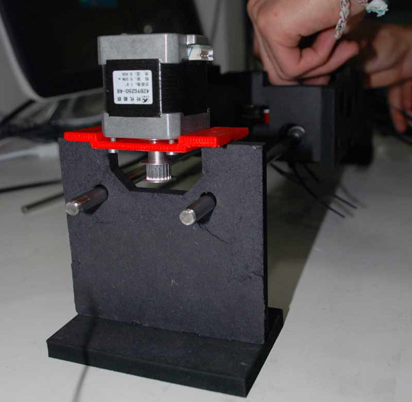
Starting with building the 3D model of the axis, in order to visualize our parameters, we gradually build the outsides, and then moved on to the inside parts which will hold the motors and support the whole structure.
Having the 3D design of our machine made it is easier to understand and troubleshoot the file for the laser-cut. At the same time, it is helpful in terms of optimizing the machine structure and parts for the following week.
We used 2mm cardboard, and get rid of a lot of cardboard. The structure is much lighter, but stiff enough.
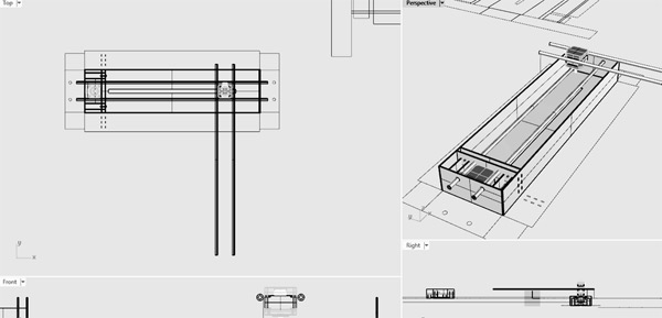
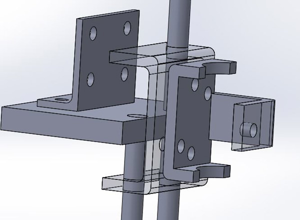
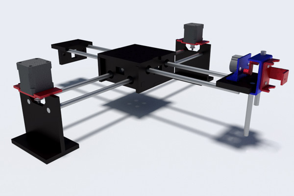
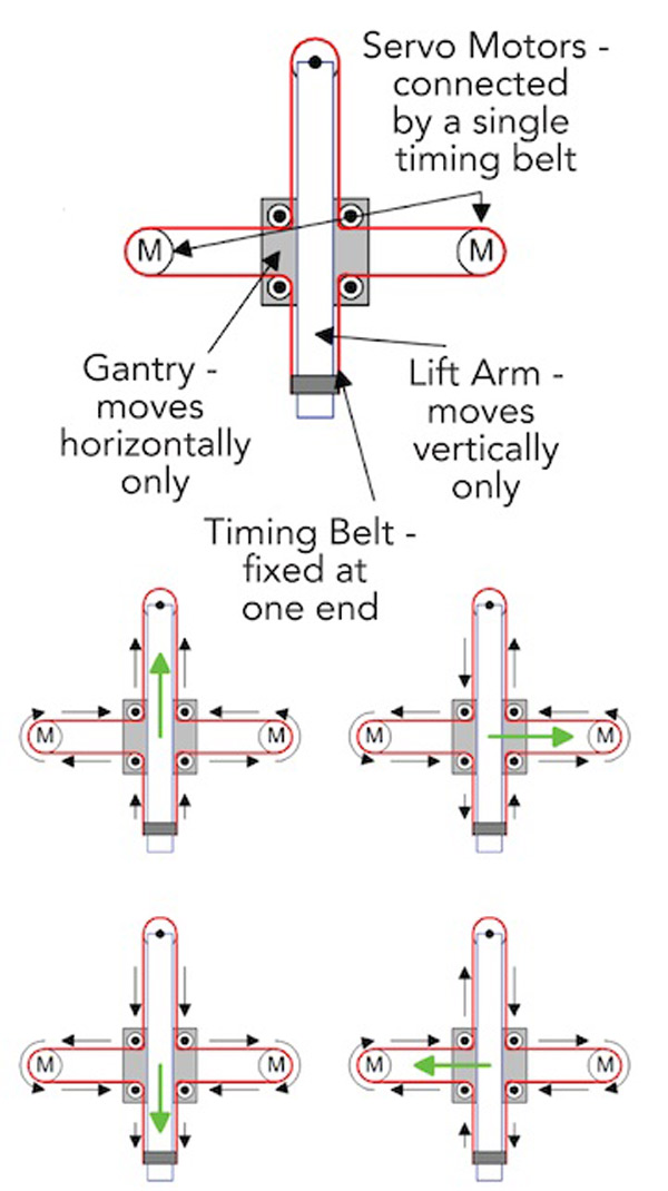
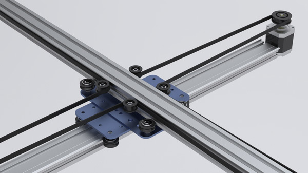
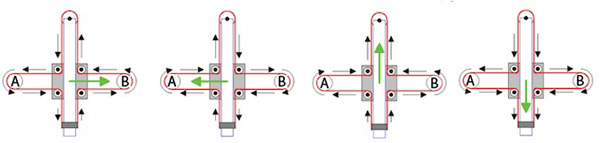
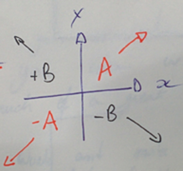
2_THE CoreXY DRAWBOT
We designed the final drawbot in Solidworks and in Rhino, this way, the files are available in both softwares.
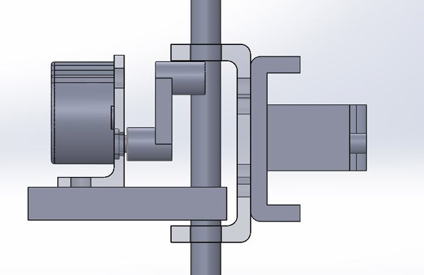
We are designing a handler with two different positions depending on how we want to position the pen: perpendicular or oblique in relation to the surface we are painting.
We will add a stepper motor for a "pen up" / "pen down" function. The problem is that we will need to make some "tricks" because the stepper is a unipolar stepper motor (with the bipolars is easier to do it).
A simulation on how the pen holder works:
Tip:
you can download Python 3.x and/or 2.x ....install both versions and use the right interpreter depending of the project. NOTE:
pyGestalt only works with Python 2.x so for that project use it!
2. Download Python IDE or Python interpreter: IDE Options Xavi's IDE election:pyCharm. It's easy for a python beginner and also quite powerful for managing python projects. Interpreter
3. Getting started: Tutorials for Beginners Python interptreter VS Python IDE (PyCharm): The interpreter is the command line in the Terminal. You can use it for programming. The PyCharm is an IDE for programming: supports listing all program files, syntax highlighting and other features.
Gestalt Framework
Gestalt is a control system framework for personal fabrication.
Two useful links for understanding the Gestalt framework: Link1 Link2
Setup Gestalt: STEP by STEP
0. A step by step guide.
1. Download pyGestalt Framework and install it.
--> in the directory where setup.py is:
sudo python ./setup.py install
2. Programming the Gestalt Node with and AVR.
Why? -> The Fabnet to node connector is not typical!
-> Are nodes already programmed? Yes, we have it.
3. Download and Install pyserial -> in order to talk over serial
-pySerial is a module to communicate python with the serial port ( Python Serial Port Extension ).
Download from here.
Installation guide. sudo python ./setup.py install
- pySerial Documentation On Mac Os installing PySerial & pyGestalt from the Terminal:
1. Download and extract pyserial.
2. Navigate via Terminal to the folder you have pyserial extracted, in this folder you should have a file called setup.py
3. Run this script sudo python setup.py install
A similar process should be done for the pyGestalt
1. Download the Nadia Peek pyGestalt framework.
2. Navigate in the command line where your pyGestalt folder is located.
3. Run the command: sudo python setup.py install.
Commands for XYCore Mechanics here. Robopaint software for drawing robots.
Firmware used in a similar machine.
Arduino 2 axis GCode interpreter.
PNG -> GCODE
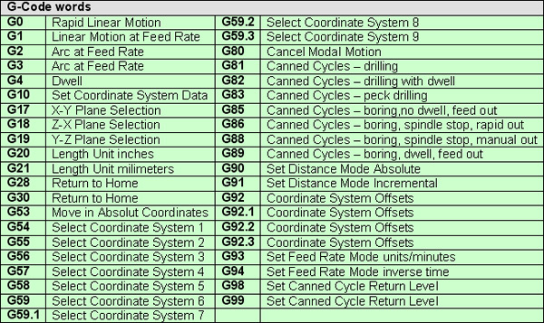
G-code is a language in which people tell computerized machine tools how to make something. The "how" is defined by instructions on where to move, how fast to move, and what path to move.
GCode specific codes.
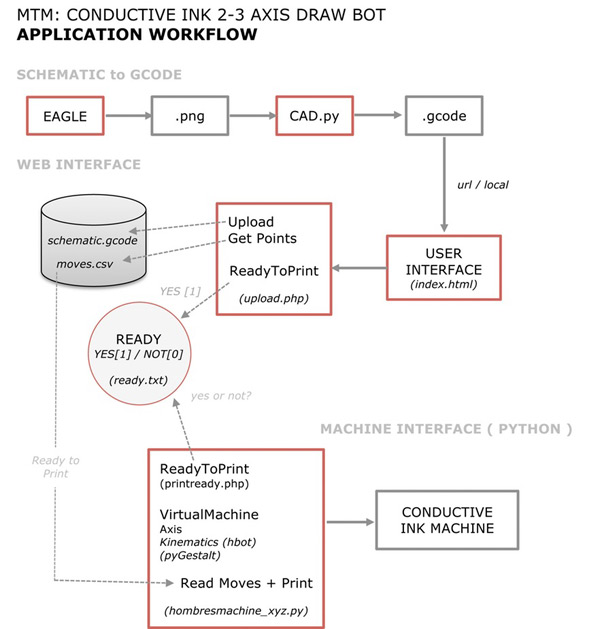
APPLICATION WORKFLOW
It's the workflow we have designed for our machine application.
Files used
"code samples" are .png generated with eagle and .gcode files samples generated with cad.py
"gcode" gcode generator ( cad.py ).
"machine app" files for the machine application.
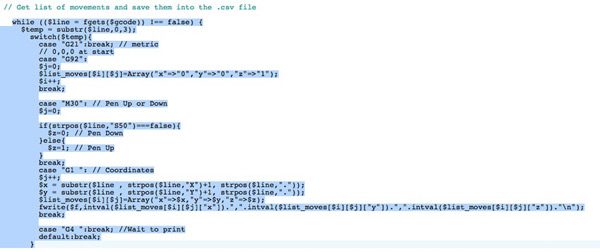
"web" files for user interface and .csv generator. PNG - GCODE
G-code is a language in which people tell computerized machine tools how to make something. The "how" is defined by instructions on where to move, how fast to move, and what path to move. Specific Codes Gcode Generators cad.py
cad.py is a single-file script by Neil Gershenfeld, capable of creating GCode files for isolation milling and drilling. Download from here Library dependencies: Numpy How to instal numpy: pip install numpy -> If you have pip installed
sudo python setup.py install -> in the numpy folder
APPLICATION PROCESS
1) When select Gcode format, prepare the output file and necessary parameters. 2) Read png and generate gcode file format. 3)Generate movement list from gcode: 4)We used PyCharm for comunicating with the gestalt nodes.
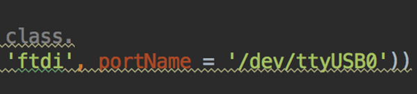
First, we need to know our USB "name", we chek it on the command line:ls /dev/tty.usb*
Then, we enter the port name on the .py file.
If it's the first time you run the code, delete the test.vmp file and run the code. The .vmp is the "virtual machine configuration". Demo: Upload to a server the .rml file and generate .gcode
5_ELECTRONICS
Link1
Motor board files: Link1 Link2
Motor Board used in Axibot: Link1
Hardware:
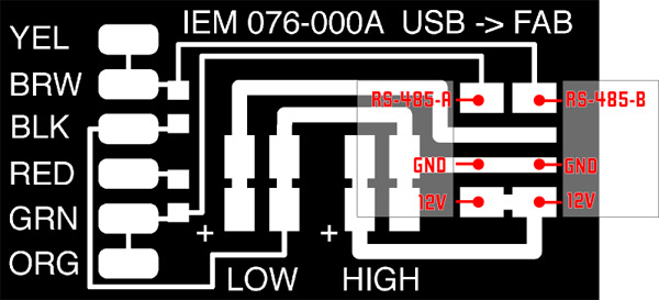
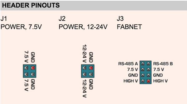
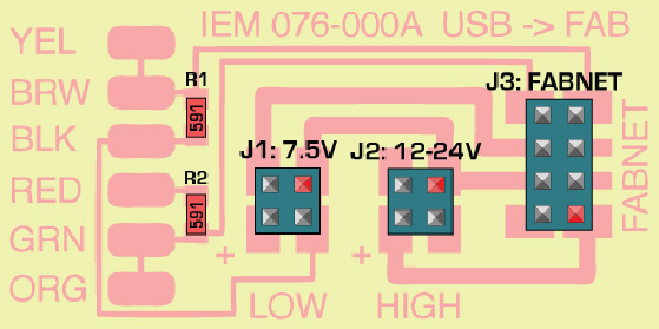
For the electronics, we need to mill the FabNET board to use it with RS-485 usb connectors:
Fabnet is a multi-drop network, meaning that multiple modules (a.k.a. nodes) share a single set of communication wires. Signalling is differential based on the RS-485 specification. Each node is assigned a four-byte IP address which uniquely identifies it over the network.
Fabnet provides power at two voltages: high voltage (12V - 24V) is intended to drive motors, lamps and actuators, while low voltage (7.5V) supplies power to the logic circuits of the nodes.
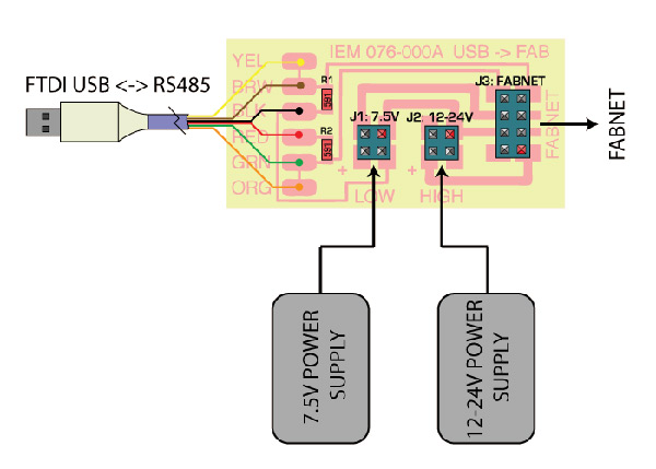
Establishing connectivity between nodes and a computer, and providing proper power, requires several components: high and low voltage power supplies, a USB-RS485 converter cable, and an adaptor board (076-000A) with bias resistors.
The next images are some diagrams to understand how the FabNET connects to Gestalt boards and power supply:
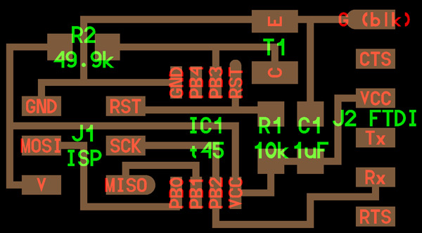
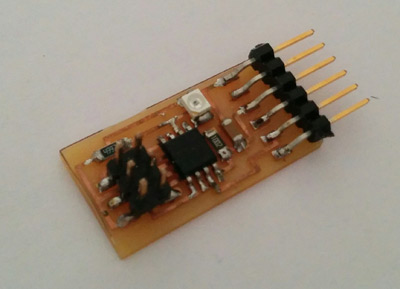
I decided to make the phototransistor.
A phototransistor is a light-sensitive transistor. A common type of phototransistor, called a photobipolar transistor, is in essence a bipolar transistor encased in a transparent case so that light can reach the base–collector junction. How it works? It's simple: a phototransistor changes its resistance based on the amount of light shining on it.
The phototransistor I used was OP580DA (datasheet).
1_DESIGN THE BOARD
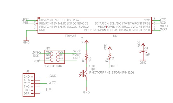
Second assignment in which I use Eagle for board design. I still don't understand too much about electronics so I based my board in Neil's design.
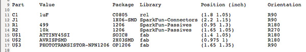
It's the list of components I added to the schematic:
Also I read de Attiny45 datasheet (only pinout configuration).
In that case I don't use an external ceramic resonator. Attiny45 has an internal 8 Mhz resonator.
I used labels for the joints between components and the microprocessor.
My final schematic
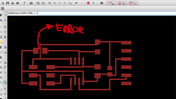
For the board design I used as reference Neils design. But during DRC check errors process I had 2 errors by the distance between traces.
To fix it I decided to change the trace width of the errors from 0.016mm to 0.012mm (Route Tool selected -> Width (in top menu)). And It worked!
And finally exported traces .png image for the milling
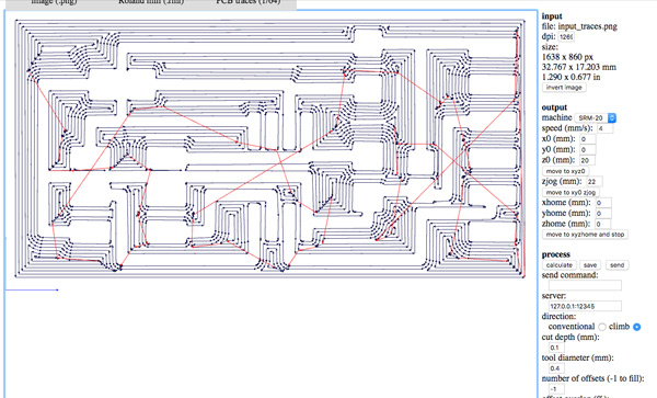
2_MAKE THE BOARD
I used fabmodules for make the board. The same process I used in the first electronics assignment but I changed 1 parameter for getting a "nice" board. Arnau suggested to me to change the number of offsets to -1. It empty copper from the board and leaves only the needed for the traces.
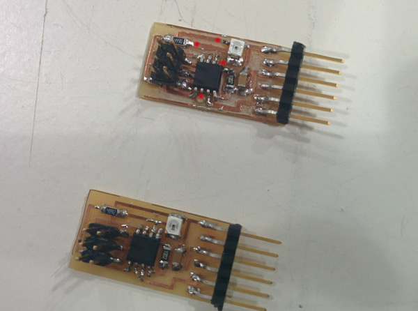
During the soldering process I make so many mistakes :( so I repeated again the milling and soldering process.
(in red errors in the first board - below the final board)
3_PROGRAMMING THE BOARD
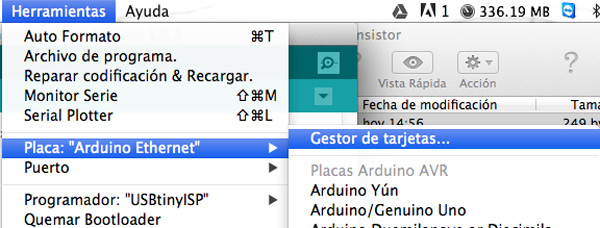
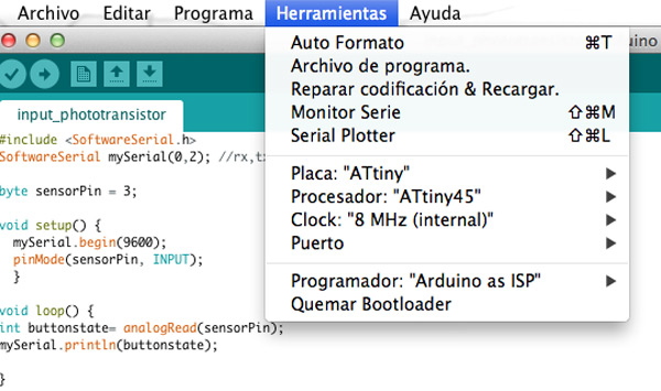
For this assignment I decided to use Arduino IDE and the Neil's python code for the programming. I had already used it Arduino but never for ATtiny boards.
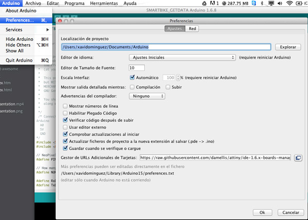
ATtiny boards are not in Arduino IDE by default so:
1.Load ATtiny package:
Arduino Preferences -> Addition Boards Manager URLs (bottom) -> Paste this URL:
https://raw.githubusercontent.com/damellis/attiny/ide-1.6.x-boards-manager/package_damellis_attiny_index.json
Save preferences
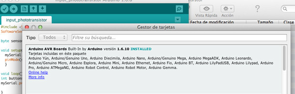
2. Install the boards -> Tools->Board->Board Manager
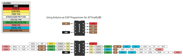
Before start programming ATtiny with Arduino IDE you need to know pinout equivalence:
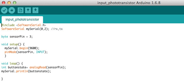
I use serial communication between the board and python code. So I used SoftwareSerial library to do it. The SoftwareSerial library has been developed to allow serial communication on other digital pins (differents of rx and tx) of the Arduino.
It's the arduino code (also in the download file):
In this assignment I used my Arduino Ethernet board as a ISP Programmer
DEMO
For the demo:
1. Connect to the USB port the board
2. Execute python program: python hello.light.45.py /dev/tty.usbserial-FT94TLIX
Note: If you want to know your usb port name-> ls /dev/tty.*
And... :)
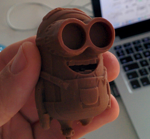
Again, a new challenge for me. The assignment for this week was to design a mold, machine it and cast part from it. I had never made one and practically I knew nothing about how was the process but finally I managed and designed a mold for cooking chocolate minions. You know, the perfect excuse if you have 2 kids [ and love chocolate :-)]. Who wants one ?
0_INTRODUCTION
When you are designing a mold, there are some things to keep in mind: 1) A mold can be one side or two side: 1 side mold
2 sides mold -> For objects that are 360º we will need a two sides mold so we have to split the model in two.
2) Choose the mold material Smooth-On is one of the best manufacturers world wide ( with distributors outside USA ).In Barcelona: FormX Spain
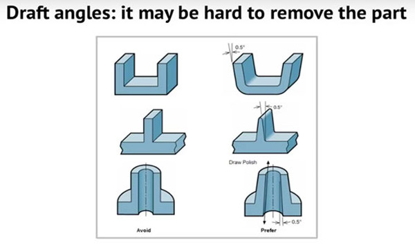
It's very important read the technician datasheet of the material and see how to work the material, its features and safety information. For example, as in my case, if the material is food safe. 3) 3D model: The negative of you want to get as a real object. 4) Draf Angle Concept
Draft is the amount of taper for molded or cast parts perpendicular to the parting line. It can be measured in degrees or mm/mm (in/in).
Some tips about it (draft angles):
· Draft is the amount of taper for molded or cast parts perpendicular to the parting line. It can be measured in degrees or mm/mm (in/in).
· Consider the fabrication of a hollow plastic box, without lid. Once the plastic has hardened around the mold, the mold must be removed. As the plastic hardens, it may contract slightly. By tapering the sides of the mold by an appropriate "draft angle", the mold will be easier to remove.
· If the mold is to be removed from the top, the box should taper in towards the bottom, such that measuring the bottom internal dimension will yield a smaller length and width than measuring the top from which the mold is extracted.
· By specifying the opening length and width, a draft angle, and a depth, it is not necessary to specify the dimensions for the internal surface, as these may be calculated from the above.
· The manufacture of a part that incorporates zero or negative angles may require a mold that can be separated into two or more parts, in order to release the casting.
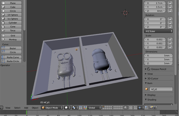
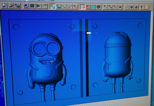
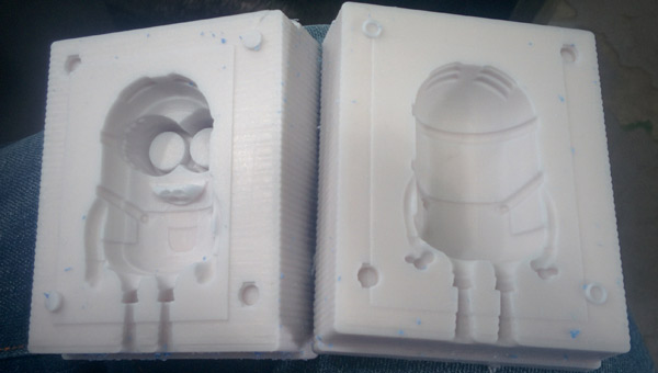
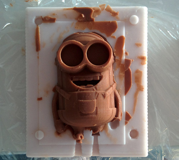
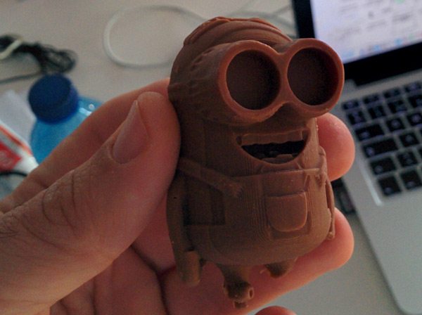
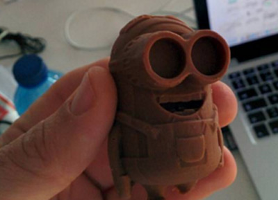
1_DESIGN A [MINION] MOLD
As I wanted a chocolate minion mold, I've designed a 2 sides mold.
For the design of the mold I've used Blender.How I don't have much experience in it, I've downloaded minion 3d model and I focused on the mold box design,trying to avoid draft angles.
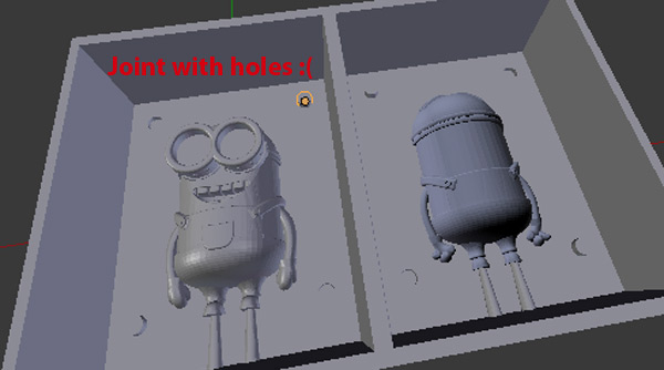
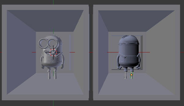
In addition to the above tips , it is important to think about how you will join the two parts to achieve an object (360 degrees). I decided to do it with holes but...
...the result didn't work quite good. So my advice is to do it with "box" joints. I changed my mold design in Blender if you want to use it.
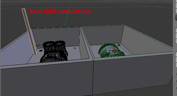
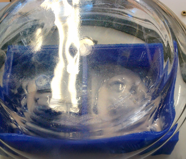
Also, it's a good idea to design a "virtual" tool (Thanks Ferdi for the recommendation!) and simulate the milling procedure
Finally, export the 3D mold model to a .stl file for the milling process.
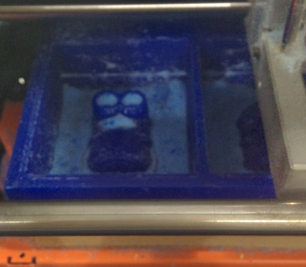
2_MILLING PROCESS
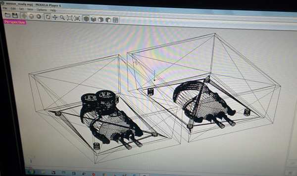
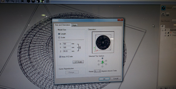
For the milling process I used the Roland SRM-20 machine and the Modela Player software (Tutorial).Step by step: 1) Open .stl model and select milling machine.
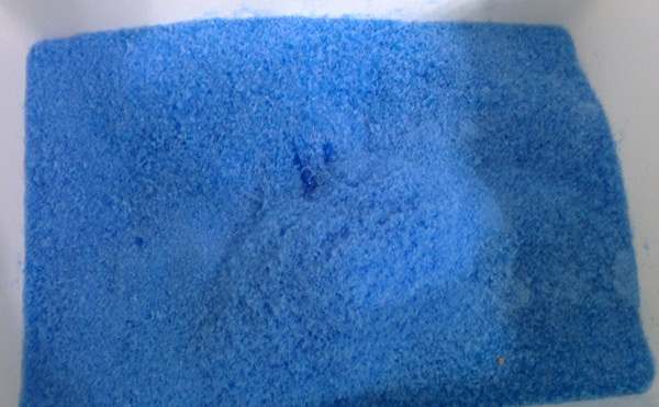
2) Select material you will use. In my case WAX which Ferdi recycles in the lab.
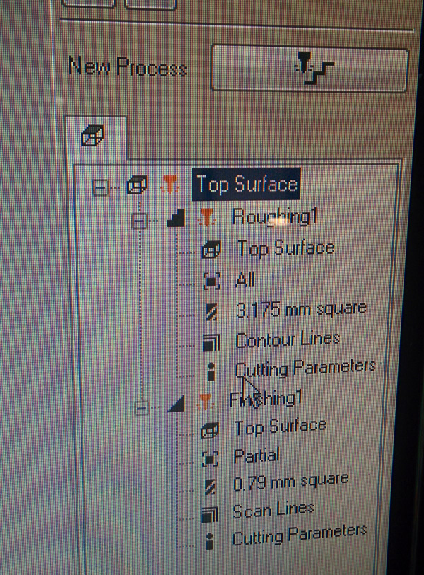
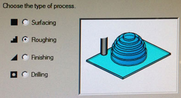
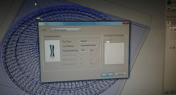
We need to create 2 process: Roughing and Finishing process for final and better details. The steps are the same but you need to change the milling bit diameter: 3.175mm square for the roughing process and 0.79mm square for the finishing.
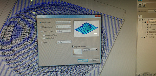
3) Create a New Process [Roughing or Finishing] 4) Choose type of proces
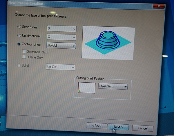
5) Choose the toolpath to create
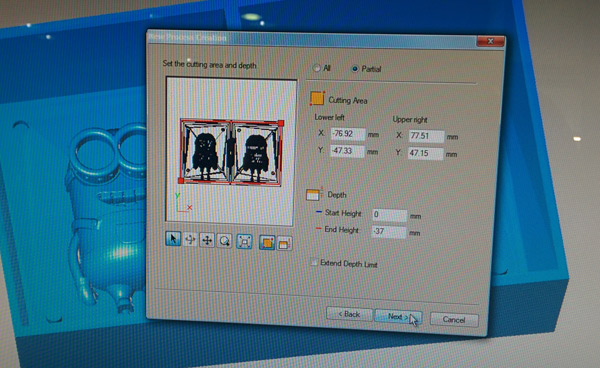
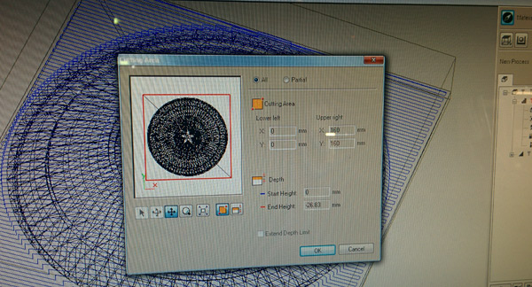
6) Define the cutting area
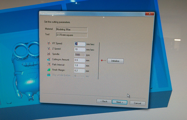
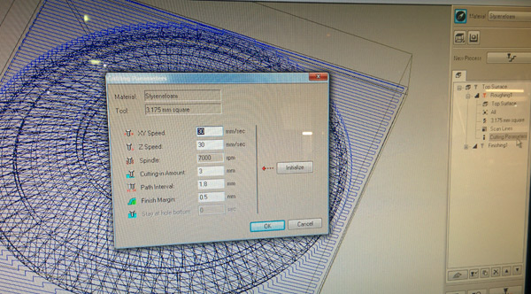
7) Set the origin and the cutting parameters
8) Generate a .mpj file, use Vpanel software and check a virtual simulation of the result
9)Go Milling!
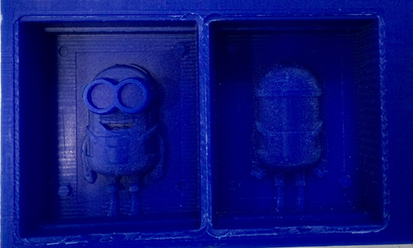
FINAL RESULT
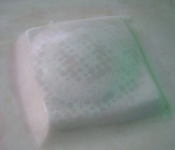
3_THE MOLD
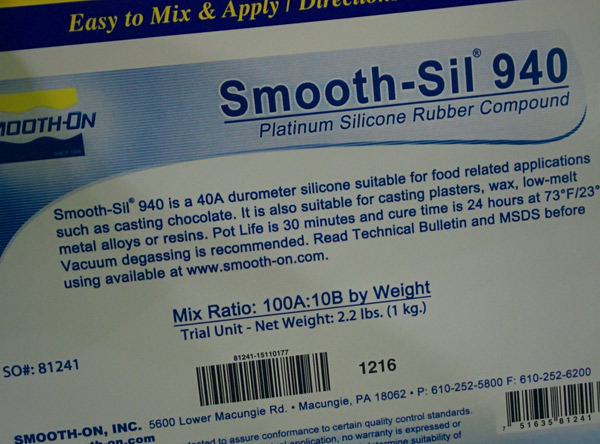
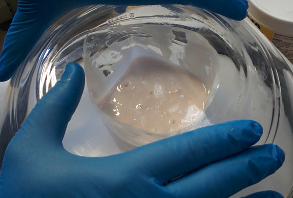
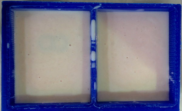
For the mold I use the Smooth-Sil® 940 Platinum Silicone
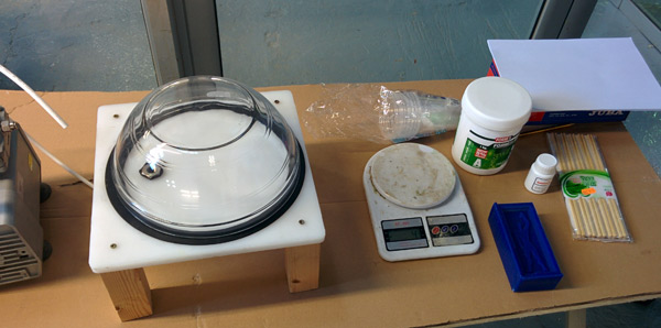
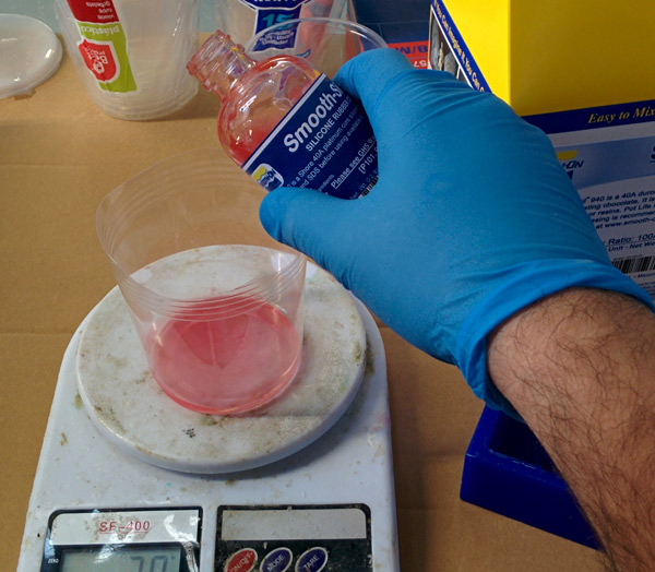
Rubber for food related applications. Again, it's important to read the product datasheet. Step by step 1) Prepares the workspace with all the tools you need:
a plastic cup for mixing,a wooden stick to mix,gloves,weighing machine ( for measure the mixing) ,vacuum machine ( Ferdi prepared one for us) and mold material.
Some tips before starting the mixture:
- Use transparent cups for mixing and see how is it going.
- 1 cm (min) silicon on top of material when you put inside the wax mold.
- Security! Take care of you!
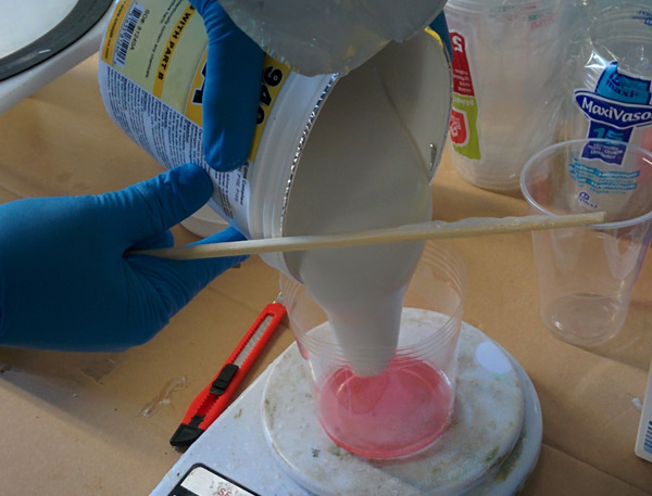
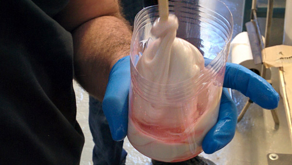
- Mix with energy!
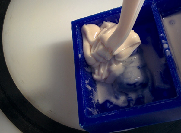
- Fill a cup with water,to get an idea of how much liquid we need for creating the mold. 2) Mixing Ratio: in my case, 100 part A to 10 part B. Mixture, 5 min at least!
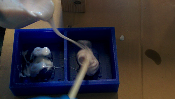
3) Try to avoid bubbles!!. Take a look this tutorial.
4) Pour the mixture into the mold wax 5) Wait 24h (in my case) before extract the silicon mold
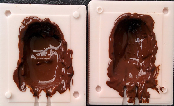
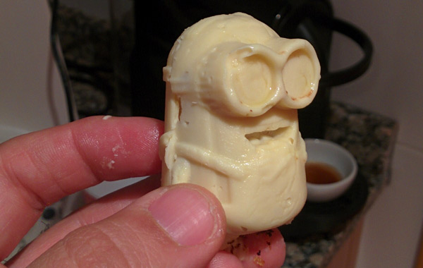
4_THE CHOCOLOTE
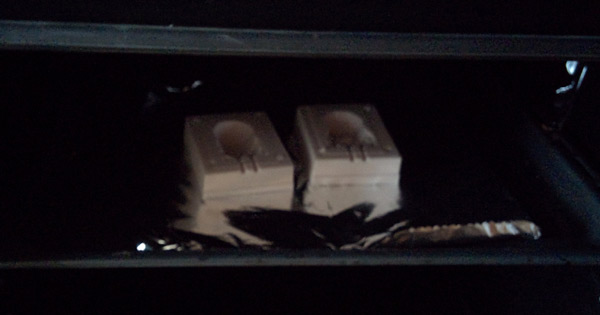
Smooth- Sil® 940 - USER INSTRUCTIONS
After the rubber mold has cured for 24 hours , it is introduced into an oven for 4 hours at a temperature of 100 °. Allow to cool and wash the mold cavity thoroughly with soap and water, rinse well and allow to dry before use.
And finally...
CONCLUSIONS
Molding and casting is a very laborious process where every detail matters.
Listen to the advice of people who have done it before!
This week was so stressful for me! In addition to making the assignment, I had to finish a final version of a software we are developing in my work...so...this week: didn't sleep too much and managed my stress :-).
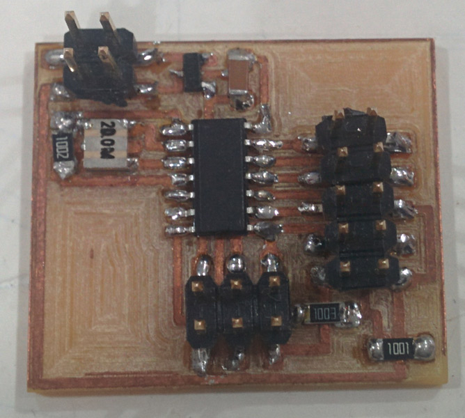
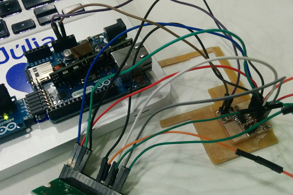
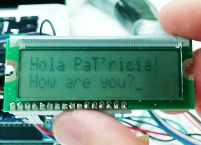
Neil and Ferdi showed us different options and I chose to design and make a board connected to a LCD screen (serial communication).
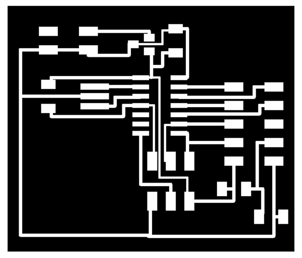
1_DESIGN THE BOARD
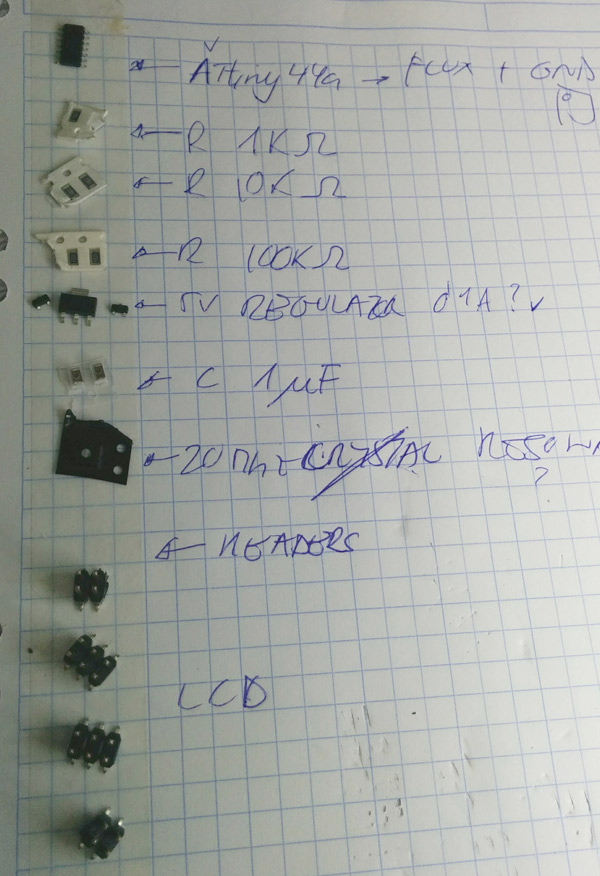
Taking Neil's board as a reference, I designed my board with Eagle. It's the list of elements I used (all available in Fab Inventory):
Again I used the ATTiny44 microcontroller.
I've gotten used to read the processor datasheet before starting the design.
Important to know the pinout configuration:
In that case I've used PINA0-PA4 for the communication with the LCD.
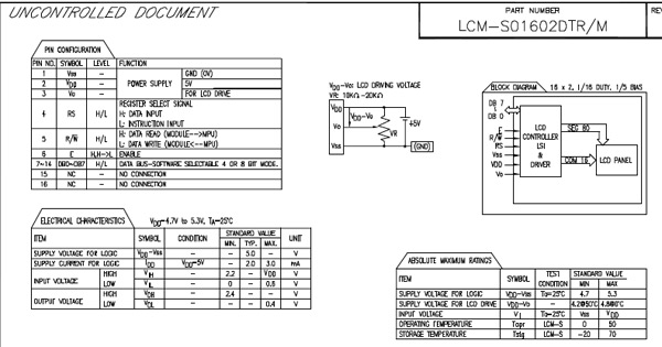
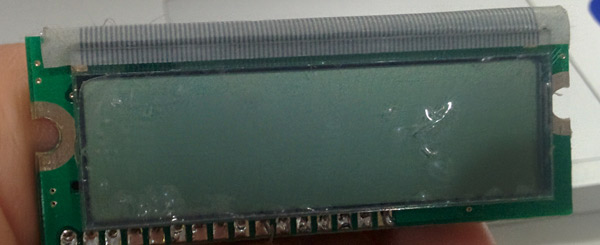
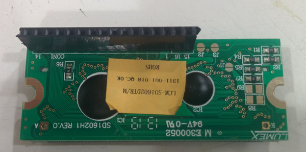
Also I read LCD datasheet (LCM-S01602DTR/M) in order to know: how to communicate with and the LCD pinout, which power(5V) it needs and which are Vin and GND pins.
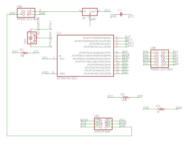
To design the schematic I haven't had any problem...It seems I begin to manage Eagle! It's the final schematic
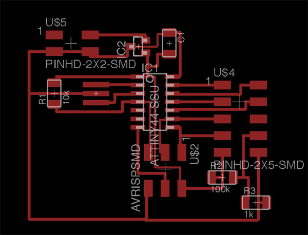
And the final board design:
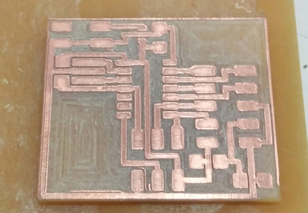
2_MAKE THE BOARD
Again for making the board I've used fabmodules + Roland SRM-20 but this time with a milling bit 1/64 for the traces that Ferdi's had modified.
Here I had some problems with the milling because I didn't check that the copper board was flat. ( Sorry Ferdi!! I'll never forget it! )
After 2 attempts, finally It is the board:
Note: Again I used the "number of offsets -1" in Fabmodules during the traces process.
Now, soldering. No problem with it. It was so easy:
Components I've used:
And also, I soldered a female header to LCD board to connect the wires between the boards.
And finally I checked board connections with the tester without any problem.
3_PROGRAMMING THE BOARD
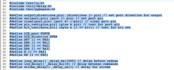
Before the makefile, I read Neil's code (in the download file) and try to understand it.
avr/io.h: for use input/output pins. util/delay.h: delay functions (ms). avr/pgmspace.h:the functions in this module provide interfaces for a program to access data stored in program space (flash memory) of the device.
If you want to understand the use of input/outputs, registers in AVR microcontrollers I recommend you to read this tutorial.
It's the code I've used:
//
// hello.LCD.44.c
//
// LCD hello-world
//
// set lfuse to 0x5E for 20 MHz xtal
//
//
//Neil Gershenfeld modified by Xavi Dominguez ( May 2016 )
// 11/14/10
//
// (c) Massachusetts Institute of Technology 2010
// This work may be reproduced, modified, distributed,
// performed, and displayed for any purpose. Copyright is
// retained and must be preserved. The work is provided
// as is; no warranty is provided, and users accept all
// liability.
//
#include
#include
#include
#define output(directions,pin) (directions |= pin) // set port direction for output
#define set(port,pin) (port |= pin) // set port pin
#define clear(port,pin) (port &= (~pin)) // clear port pin
#define pin_test(pins,pin) (pins & pin) // test for port pin
#define bit_test(byte,bit) (byte & (1 << bit)) // test for bit set
#define LCD_port PORTA
#define LCD_direction DDRA
#define DB7 (1 << PA0)
#define DB6 (1 << PA1)
#define DB5 (1 << PA2)
#define DB4 (1 << PA3)
#define E (1 << PA4)
#define RS (1 << PA5)
#define long_delay() _delay_ms(1000) // delay before redraw
#define lcd_delay() _delay_ms(10) // delay between commands
#define strobe_delay() _delay_us(1) // delay for strobe
//
// lcd_putchar
// put character in lcdbyte
//
void lcd_putchar(char lcdbyte) {
//
// set RS for data
//
set(LCD_port, RS);
//
// output high nibble
//
if bit_test(lcdbyte, 7)
set(LCD_port, DB7);
else
clear(LCD_port, DB7);
if bit_test(lcdbyte, 6)
set(LCD_port, DB6);
else
clear(LCD_port, DB6);
if bit_test(lcdbyte, 5)
set(LCD_port, DB5);
else
clear(LCD_port, DB5);
if bit_test(lcdbyte, 4)
set(LCD_port, DB4);
else
clear(LCD_port, DB4);
//
// strobe E
//
strobe_delay();
set(LCD_port, E);
strobe_delay();
clear(LCD_port, E);
//
// wait
//
lcd_delay();
//
// output low nibble
//
if bit_test(lcdbyte, 3)
set(LCD_port, DB7);
else
clear(LCD_port, DB7);
if bit_test(lcdbyte, 2)
set(LCD_port, DB6);
else
clear(LCD_port, DB6);
if bit_test(lcdbyte, 1)
set(LCD_port, DB5);
else
clear(LCD_port, DB5);
if bit_test(lcdbyte, 0)
set(LCD_port, DB4);
else
clear(LCD_port, DB4);
//
// strobe E
//
strobe_delay();
set(LCD_port, E);
strobe_delay();
clear(LCD_port, E);
//
// wait and return
//
lcd_delay();
}
//
// lcd_putcmd
// put command in lcdbyte
//
void lcd_putcmd(char lcdbyte) {
//
// clear RS for command
//
clear(LCD_port, RS);
//
// output command bits
//
PORTA = lcdbyte;
//
// strobe E
//
strobe_delay();
set(LCD_port, E);
strobe_delay();
clear(LCD_port, E);
//
// wait and return
//
lcd_delay();
}
//
// lcd_putstring
// put a null-terminated string in flash
//
void lcd_putstring(PGM_P message) {
static uint8_t index;
static char chr;
index = 0;
while (1) {
chr = pgm_read_byte(&(message[index]));
if (chr == 0)
return;
lcd_putchar(chr);
++index;
}
}
//
// lcd_init
// initialize the LCD
//
void lcd_init() {
//
// power-up delay
//
lcd_delay();
//
// initialization sequence
//
lcd_putcmd(DB5+DB4);
lcd_putcmd(DB5+DB4);
lcd_putcmd(DB5+DB4);
//
// 4-bit interface
//
lcd_putcmd(DB5);
//
// two lines, 5x7 font
//
lcd_putcmd(DB5);
lcd_putcmd(DB7);
//
// display on
//
lcd_putcmd(0);
lcd_putcmd(DB7+DB6+DB5);
//
// entry mode
//
lcd_putcmd(0);
lcd_putcmd(DB6+DB5);
}
int main(void) {
//
// main
//
// set clock divider to /1
//
CLKPR = (1 << CLKPCE);
CLKPR = (0 << CLKPS3) | (0 << CLKPS2) | (0 << CLKPS1) | (0 << CLKPS0);
//
// initialize LCD pins
//
clear(LCD_port, DB7);
output(LCD_direction, DB7);
clear(LCD_port, DB6);
output(LCD_direction, DB6);
clear(LCD_port, DB5);
output(LCD_direction, DB5);
clear(LCD_port, DB4);
output(LCD_direction, DB4);
clear(LCD_port, E);
output(LCD_direction, E);
clear(LCD_port, RS);
output(LCD_direction, RS);
//
// initialize LCD
//
lcd_init();
//
// main loop
//
while (1) {
//
// go to zero position
//
lcd_putcmd(0);
lcd_putcmd(DB5);
//
// print first line from flash
//
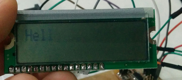
static const char line1[] PROGMEM = "Hola PaT'ricia!";
lcd_putstring((PGM_P) line1);
//
// move to second line
//
lcd_putcmd(DB7+DB6);
lcd_putcmd(0);
//
// print second line from flash
//
static const char line2[] PROGMEM = "How are you?";
lcd_putstring((PGM_P) line2);
//
// pause
//
long_delay();
//
// clear display
//
lcd_putcmd(0);
lcd_putcmd(DB4);
}
}
}
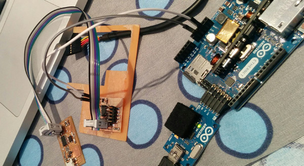
Last step, makefile: sudo make -f hello.LCD.44.make program-usbtiny
I used my ISP for programming the outputboard and my arduino ethernet board for giving it power:
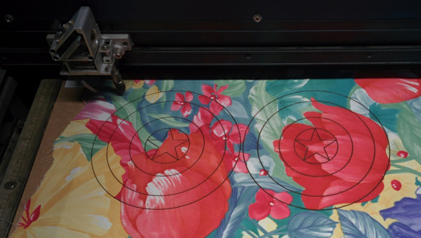
What do you make if you're father of a little child fan of superheroes and you have to produce a fiber composite part? Yes, a Captain America shield! Well actually , my exercise this week has been an attempt. I followed the whole process and I learned a lot of things ... but the final result ... say it is only a first prototype... I hope to repeat in the future to get a good shield for my son!
0_INTRODUCTION
At the beginning of the week I did not understand very well how to do my exercise. What was the process to be followed , the necessary materials...So I search in Google about materials, process, ideas, talked with Santi and reviewed again Neil lecture and Ferdi's review.
Finally:
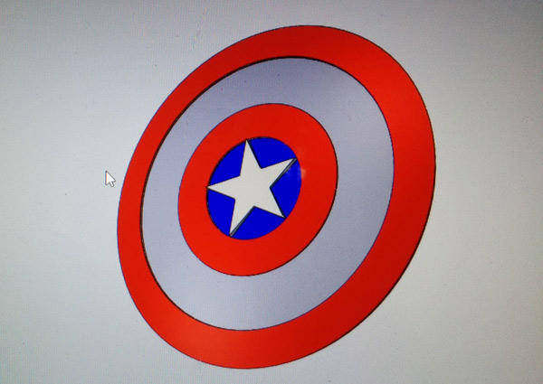
I decided what to make: design a captain america shield mold.
Which material I'll use:fiberglass. Fiberglass is a type of fiber-reinforced plastic where the reinforcement fiber is specifically glass fiber. The glass fiber may be randomly arranged, flattened into a sheet (called a chopped strand mat), or woven into a fabric. The plastic matrix may be a thermosetting plastic – most often epoxy, polyester resin – or vinylester, or a thermoplastic.
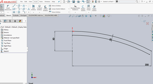
And what is the process to follow: design the shield (which not need a lot of detail) in SolidWorks, milling it and "fiberglass". It's a very good step by step guide.
1_DESIGN A MOLD
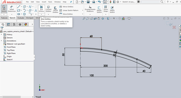
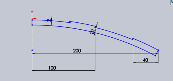
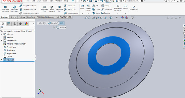
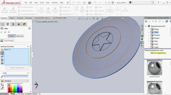
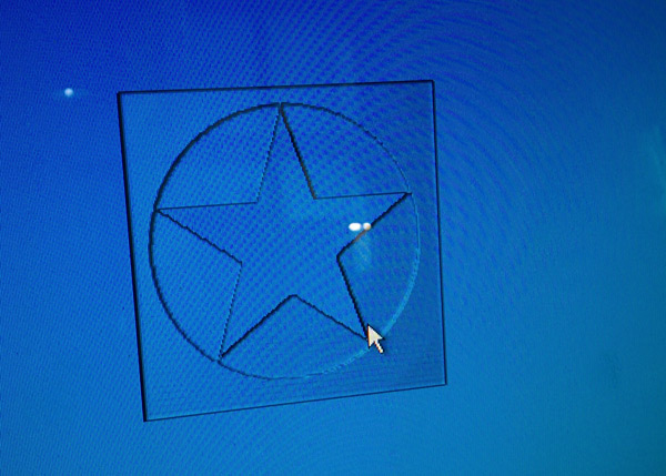
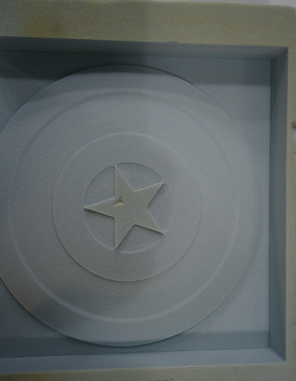
For designing it I've used SolidWorks. Pau is 4 years old so I've designed a "small" shield. The 3D technique I've used in Solidworks has been to create the shape and contour of the shield and then make the 3d object with the "revolve" tool.
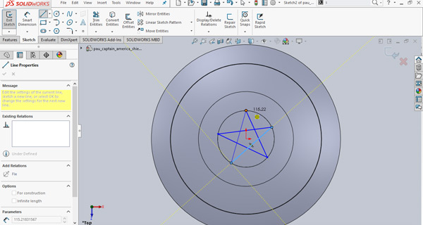
Finally, add the start and extrude it to give some detail to the shield.
TIP:exaggerates the details in the design.It's not easy to get detail when you apply the fiber. I did not and the end result is not very detailed.
2_FABRICATE A MOLD
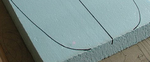
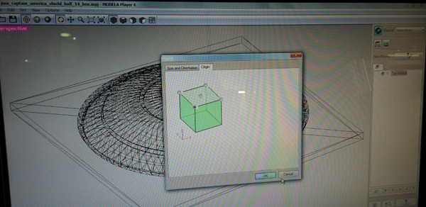
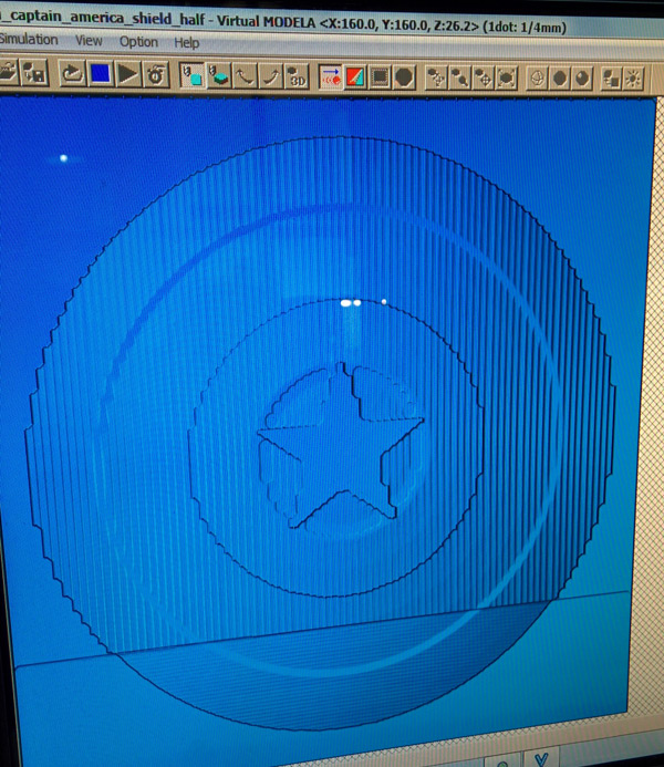
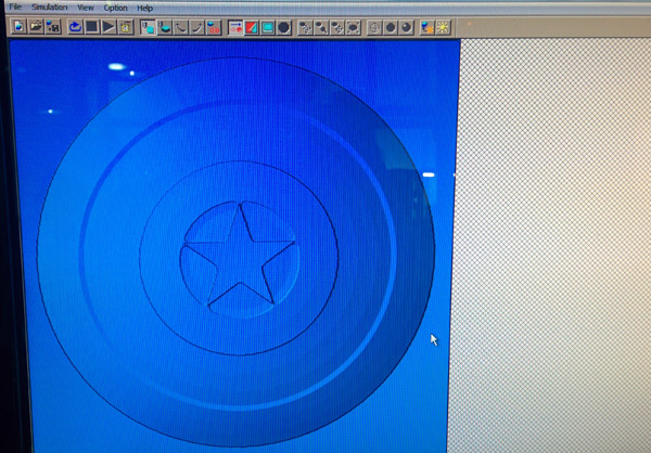
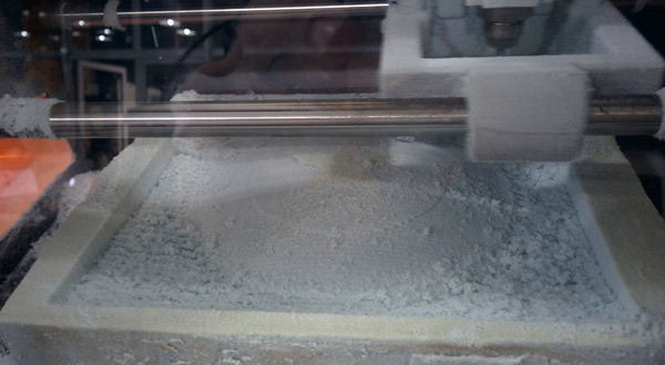
Next step is milling the mold. For this assignment I used again the Roland SRM-20 because the Shopbot was busy with all my colleagues and some IAAC's students. Also this week I had a business trip so I didn't wait for the Shopbot. The process is the same but Roland SRM-20 is for "small" molds. Step by step 1) Export the model in an .stl file. 2) Choose the mold material. In my case,styrene foam.
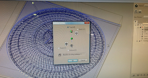
3) Import .stl file to the Modela Player Software. 4) Create a Roguhing Process.I also did a finishing process to give more detail to the star in the shield.
5) Go milling!
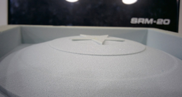
6) Final mold
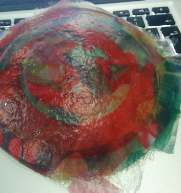
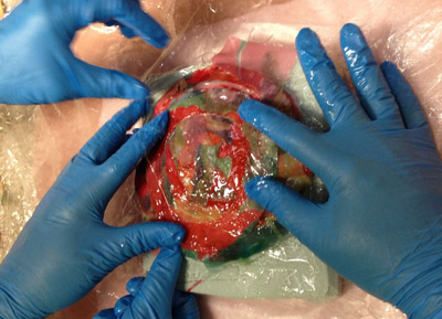
3_FIBER COMPOSITE
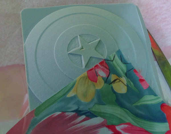
Next step, create the fiber composite shield. I decided to use as a fiber printed cloth.
Also I used laser cutting for give shield shape to the textile. Maybe it was a mistake because it is not necessary to do it for a better detail.
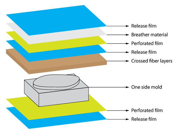
It is important to take into account the different layers needed. Following the advice of Janaki , I noticed this pict from Gabriel Pasetti website. Gabriel is a fabacademy student with very good documentation!
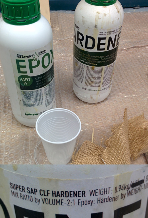
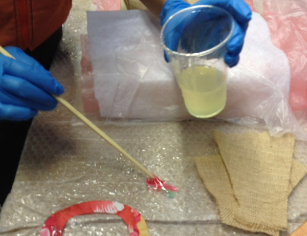
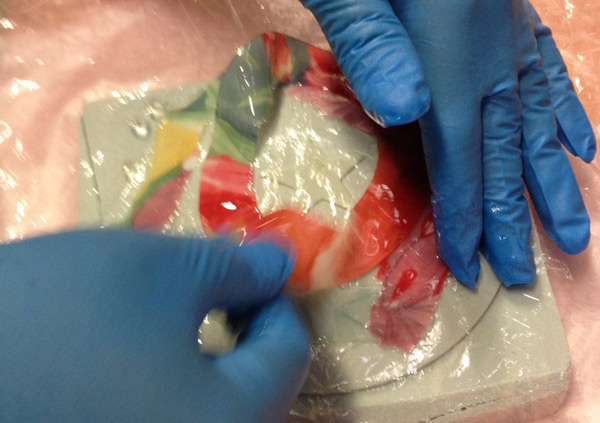
The mix ration for the casting is 2 Epoxy resin and 1 Hardener
Next picts show casting process. Note:Thanks to my friends Janaki and Arnau for their help during the process!
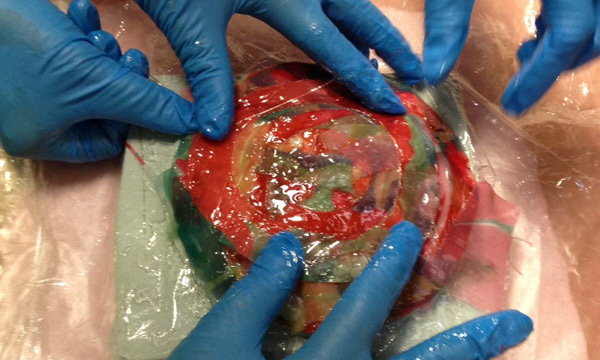
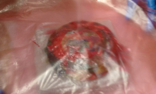
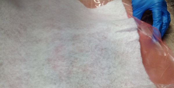
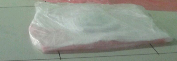
The last step (and important!) is to place the composite part and the mold in the vacuum machine. IMPORTANT!:Place 3 layers on the top and underneath the whole model. Underneath:first a perforated film,the cotton breather and the plastic film.And on the top the same 3 layers but in inverse order.
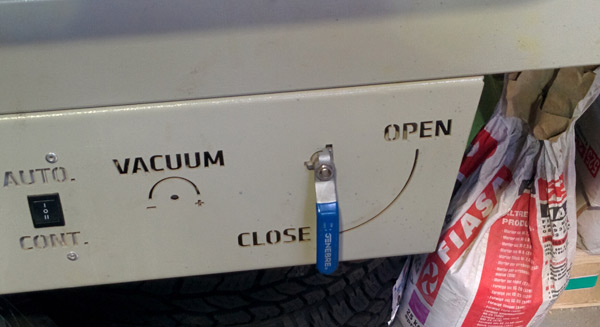
Now, close the machine, put it during 1 minute in continuos mode and after that in auto mode (Santi's recommendation). Tip: Don't obstruct any hole from the machine! It doesn't work properly if you do it.
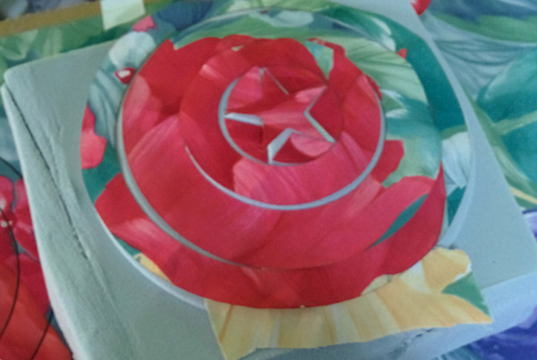
And after 12hours (at least!)...it's the result (a small shield :-)):
It liked Pau but...we need to paint it!!!(after fabacademy :-)).
CONCLUSIONS
Put as many layers as you can as a fiber!!!It will make more resistant your composite.
Be careful with the Epoxy and the Hardener. It can be dangerous in contact with your skin.
Well..the end of the fabacademy is coming! In this assignment I wanted to take this assignment to start preparing my final project. So my idea was to design a network communication (bluetooth) between a board designned by me ( with a bluetooth module connected) and a mobile app (programmed by me in appinventor).
1_IMPORTANT CONCEPTS
SYNCHRONOUS / ASYNCHRONOUS COMMUNICATION
This example perfectly resums:"Calling someone on telephone is synchronous. Communicating with him per mail is asynchronous" :-) Easy, is it?.
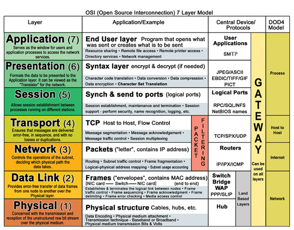
OSI LAYERS
The Open Systems Interconnection model (OSI model) is a conceptual model that characterizes and standardizes the communication functions of a telecommunication or computing system without regard to their underlying internal structure and technology.
MASTER / SLAVE COMMUNICATION
Master/slave is a model of communication where one device or process has unidirectional control over one or more other devices. In some systems a master is selected from a group of eligible devices, with the other devices acting in the role of slaves.
SPI
Serial Peripheral Interface (SPI) is an interface bus commonly used to send data between microcontrollers and small peripherals such as shift registers, sensors, and SD cards. It uses separate clock and data lines, along with a select line to choose the device you wish to talk to.
BLUETOOTH
Bluetooth is a wireless technology standard for exchanging data over short distances (using short-wavelength UHF radio waves in the ISM band from 2.4 to 2.485 GHz[4]) from fixed and mobile devices, and building personal area networks (PANs).
So the network I've designed has: synchronous communication (board and mobile app), wireless network (bluetooth).Let's see how I did it!
2_DESIGN THE BOARD
Thinking on my final project I need a board with many inputs and outputs pins for connecting and communicating:bluetooth module, sensor module, some LEDs and a power supply.
Also a powerful microcontroller, ATtiny maybe will not be enough.
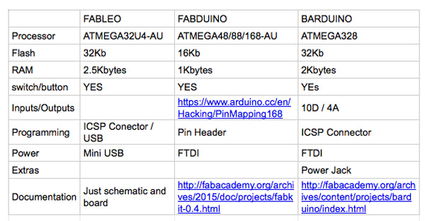
So I decided to make an arduino board, but which one? I did a table comparing the different options.
Finally I choose to based my design in FABLEO because:
1. I don't need an FTDI cable, just a micro-usb.
2. ATMEGA32U is better than the others.
3. Although there is not much documentation available , other colleagues also have used it and if I need help they will help me.
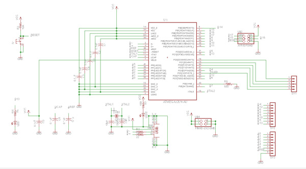
As always I did the design in Eagle.
List components I used (available in download files):
I did some changes to the original fableo board:
1. I did it smaller. Removing some leds I didn't use and changing digital inputs position to the top.
Also I added some new inputs because I need use TX and RX pins from the ATMEGA32U.
I kept switch button and 2 LEDs integrated in the board becaused I'll use it for the programming.
In the schematic I hadn't any special problem.
The final schematic
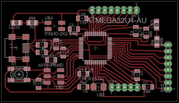
But in the board design I had some problems with the traces. It was not easy to make a "small board", enough width tracess and pass the DRC check process.
At least I managed but in future iterations I had to make it smaller.
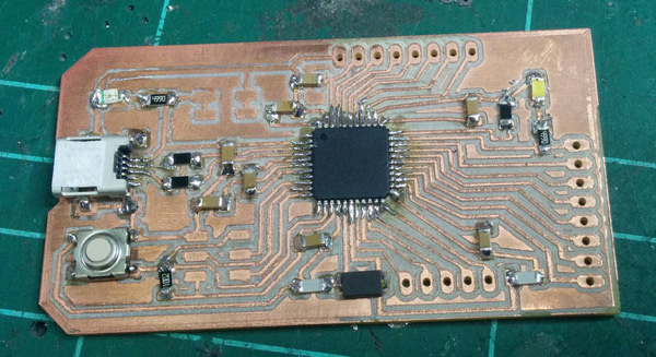
The final board - XAVDUINO
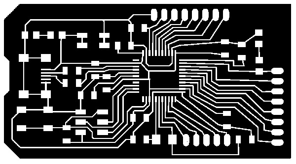
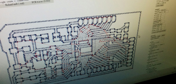
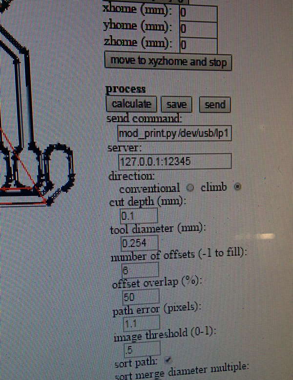
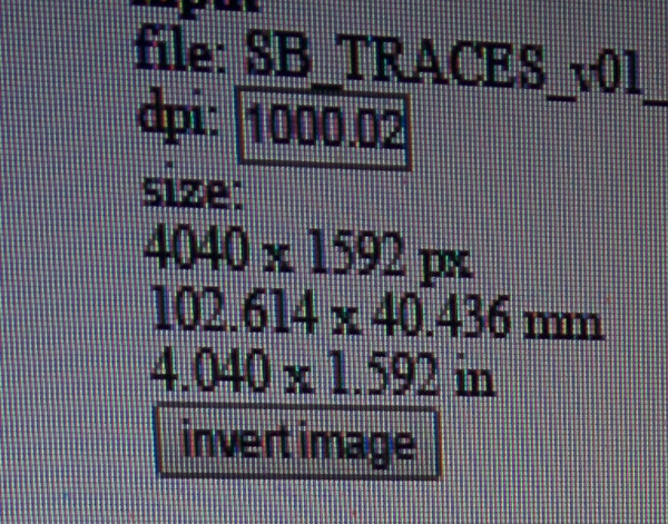
3_MAKE THE BOARD
As always I used fabmodules and Roland SRM-20 machine.
I had one problem milling XAVDUINO: making the holes with the 1/32 milling bit you need to use the "INVERT IMAGE" option. It make holes inside and not outside (big).
I had to repeat the milling process.
Soldering the XAVDUINO it wasn't easy but I managed.
For soldering the ATMEGA32U I used Flux.It makes soldering easier,soldered lead easily bonds on the copper pads.
After soldering I did the connections check with the tester and detect that 2 legs of the microcontroller weren't well soldered. I fixed it soldering again.
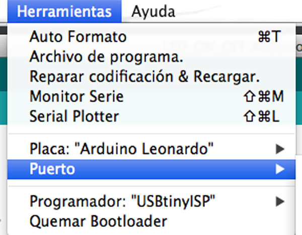
I used my fabisp as a programmer and Arduino IDE tool to do the bootloader.
In Arduino IDE top menu choose Board->Leonardo and the USB port.
Then choose USBtiny as a programmer
Connect the XAVDUINO to the usb port
Burn bootloader.
I had no problem but for testing I upload BLINK sample to XAVDUINO and it worked!!
5_BLUETOOTH MODULE
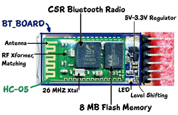
For the communication I used the JBtek-HC-05 Wireless module
Some information about this module:
1. Bluetooth module HC-05 Master and slave->Two in one module
2. Use the CSR mainstream bluetooth chip, bluetooth V2.0 protocol standards
3. Module working voltage 3.3 V
4. Potter default rate of 9600, the user can be set up
5. The core module size : 28 mm x 15 mm x 2.35 mm
6. Datasheet
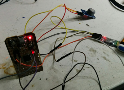
Now it's time to configurate the bluetooth module.
I use XAVDUINO board for the configuration connecting it to my computer and uploading an empty sketch. void setup(){} void loop(){}
Then connect Rx/Tx pin XAVDUINO to Rx/Tx of bluetooth module.
Also 5v XAVDUINO to VCC HC-05.
GND XAVDUINO to GND HC-05.
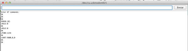
Now use the SERIAL Monitor of the Arduino IDE to feed AT commands.
At the bottom of the SERIAL monitor ensure that you select “BOTH NL & CR”.
Type in AT+click on Send.
You should get a OK response from the module.
1. SLAVE mode.
The slave modules can not initiate a connection to another Bluetooth device, but can accept connections.Master module can initiate a connection to other devices.
By default ROLE of HC-05 is SLAVE.
Type AT+ROLE to confirm it.
2. PASSWORD: AT+PSWD to know the password. By default is 1234
3. AT+UART to Baudrate
4. AT+NAME to change the name
Now it's time to programm a mobile app for the comunication between XAVDUINO and my mobile phone.
5_MAKING A MOBILE APP
I did the networking communication between XAVDUINO and my mobile phone via bluetooth. So I needed to program an app which I'll use for my final project.
I programmed it with APPINVENTOR.
MIT App Inventor is an online tool to programming and app creation that transforms the complex language of text-based coding into visual, drag-and-drop building blocks.
First I did the user interface
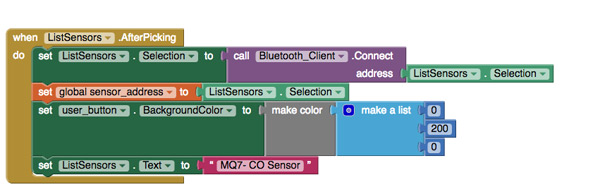
And then "programm" bluetooth to connect to the HC-05 module
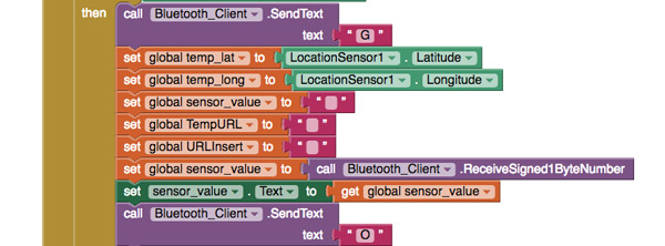
When it is connected, sends a "G" char to Arduino programm for read sensor value and print it in the mobile screen.
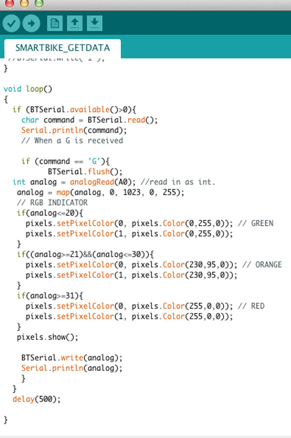
6_ARDUINO BLUETOOTH PROGRAMMING
(code available in the downloads file)
For my final project I need a sensor(MQ-7), so I used in this assignment to read values and send to the mobile app.
I also use this assignment to advance my final project ( Smart Bike Project ). The process is:
1. Get data from a pollution sensor (input) connected to a XAVDUINO (electronic board designed by me). Arduino + Serial
2. Connect this device and send the data to a mobile APP via Bluetooth (output). APP Inventor + Serial
3. Upload this data to a database server in the cloud (input).APP Inventor+PHP+MySQL
4. Show a heat map with more pollution areas in a web application (output).PHP+MySQL+(JavaScript+JQuery)
The electronic design and network communications between the sensor+board+mobile app I already explained in networking and communications assignment.
So now I'll explained more detailed the interfaces I've used.
Note: This assignment was updated when I finished final project.
1_APP INVENTOR
I already had experience programming with App Inventor.
It's visual, blocks language for building Android Apps and also for learning programming.Build apps is very fast with this great tool.
I'm part of the Vailets Hacklab group. We make events and workshops for kids and I use App Inventor to teach programming.
How I did Smart Bike Project App?
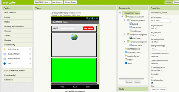
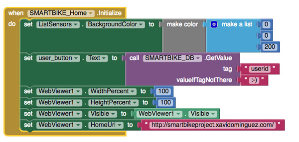
1. FRONT END APPLICATION
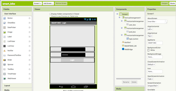
First, design user interface of the app with the App Inventor Designer Smart Bike Project - Log in screen
SmartBIKE_DB -> Local Database for recording sensor data in the mobile.
WebBridge -> HTTP connections to a server database for user verification.
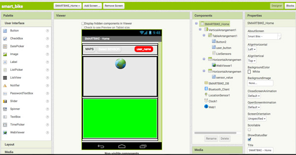
Buttons -> UX Smart Bike Project - Data screen
Bluetooth Client -> Use Mobile Bluetooth chip for connect the app to the smart device.
Location Sensor -> For get geolocation data.
Clock -> For request sensor data each X seconds.
Web -> Show maps for the mobile user (under development).
Buttons -> UX, Select Bluetooth Device. Sensor Value -> Print the value of the enviromental sensor Background Color -> It changes depending the value of the sensor (green, orange, red) 2. BACK END APPLICATION
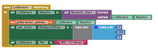
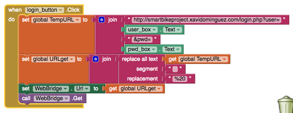
For the back end programming you have to use the App Inventor Block Editor.
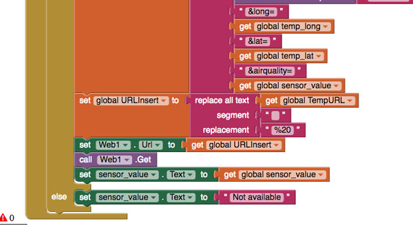
It's the part that connects with the bluetooth module, the cloud server, php gets.
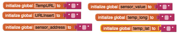
Global variables
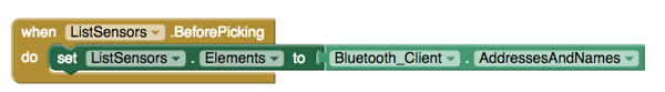
Get a list of the bluetooth nearest devices
Initialize Data Screen (map, user name, data sensor value and background,bluetooth devices...)
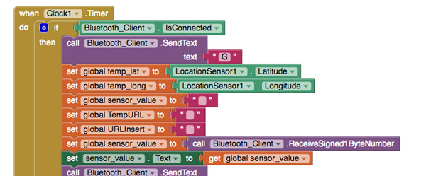
Bluetooth connection
Check if bluetooth from the device is available, get geolocation data (long, lat),initialize variables,get sensor value from the device and send confirmation
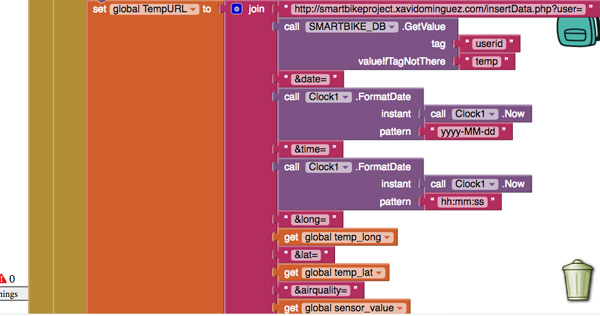
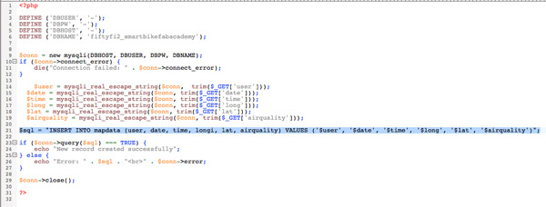
Insert data in the Database Server calling a .php file (insertData.php) which executes a insert query.
Print data in the mobile interface, change color or alert user bluetooth device is not available
User verification process
Save information in local database
3. DEMO
2_MySQL: SERVER DATABASE
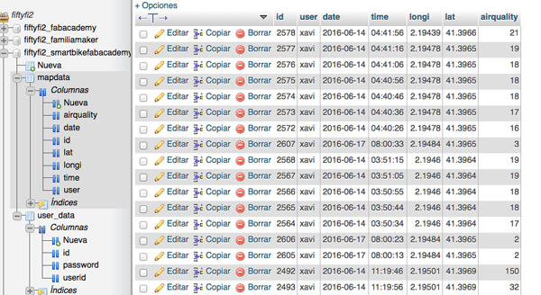
You can go to the web application with this link. In a server I created a Smart Bike Database in a MySQL system. (available in download files)
I insert, update, read data with sql queries. It's an example of the data stored and database structure.
Insert data php and query example
Note: All files available in download files
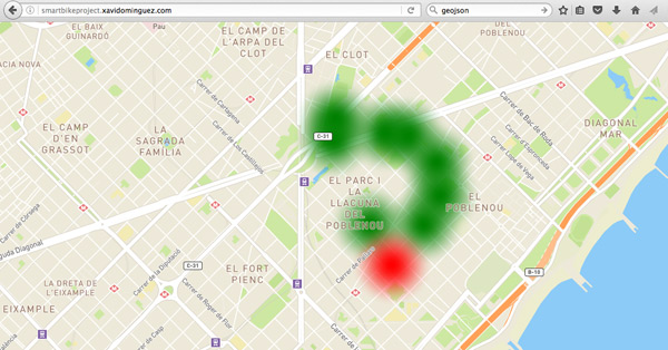
3_WEBAPP: MAPBOX+JAVASCRIPT+HTML5+PHP+GEOJSON
For visualize data from the sensor I developed a Web Application available here (webapp code available in download files)
I've used: MAPBOX + GEOJSON Mapbox is the mapping platform for developers.
I tried other platforms like CartoDB or API Maps Google but I think Mapbox is the best option because they have availiable libraries for developers in different languages like javascript (great for me!), python...also a lot of documentation and a big developers community.
How it works : Design a map, add data, programming it, upload to a website.
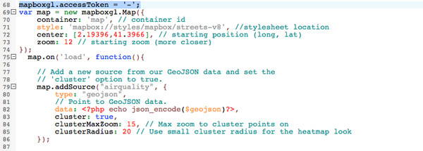
All you need to start using Mapbox is an access token.
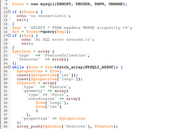
Before adding data to the map I convert it (php) to GeoJSON. GeoJSON is a format for encoding a variety of geographic data structures. In my case: user id, lattitude, longitude, airquality (sensor value)
How I did it? Code comments:index.php
Read data from database and transform to GeoJSON format
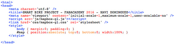
Import Mapbox javascript library and map style
Initialize map with javascript, read TOKEN and add data to the map
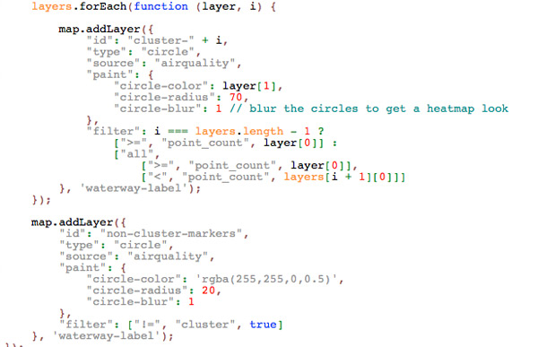
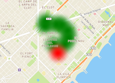
Add points to the map and paint heatmap color depending of sensor values DEMO
Note: Red area is near the FabLab where I got more values so the device was more precise.
I've decided to make Smart Bike Project to alert the pollution that we suffer in the big cities.
It is divided in 3 parts:
1. A sensor device that collects geolocation and environmental data (monoxide carbon,noise), while the urban cyclist make their daily route.
2. Also a mobile application connects to the sensor (via Bluetooth) and upload the data to a database on a server in real time (monitors sensor data and the location of each minute).
3. Finally there is a website where you can see the most polluted areas of the city.
So the idea is to collect data, share, learn with this information and alert society to the problem we have.
1. Microcontroller
2. Power Supply
3. Battery(Lipo or 9v)
4. Environmental sensors ( monoxide carbon+sound sensor)
5. Bluetooth Module
6. LED's
7. Bike case
8. Mobile phone with GPS and Bluetooth
9. Server (web+database)
10. PLA for the 3D printed parts
11. Acrylic for laser cutting
12. Milling machine for making the board
13. Jumpers
14. Electronics components for the board
1. Microcontroller:3.4€
2. Power Supply:0.5€
3. Battery(Lipo or 9v):0.5€
4. Environmental sensors ( monoxide carbon+sound sensor):4€
5. Bluetooth Module:8€
6. LED's:1€
7. Bike case:2€
8. Mobile phone with GPS and Bluetooth:depends model and brand
9. Server (web+database):60€/year
10. PLA for the 3D printed parts:20€/Kg
11. Acrylic for laser cutting:2€
12. Milling machine for making the board: FABLAB
13. Jumpers:2€
14. Electronics components for the board:4€ Total:108€
(including cloud server and database rent)
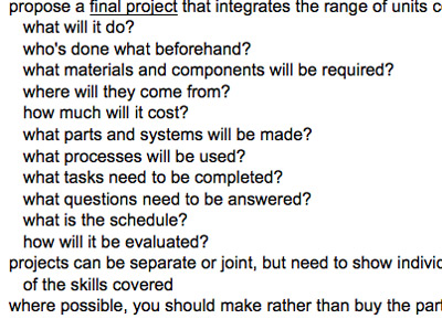
5_WHAT PARTS AND SYSTEMS WILL BE MADE??
1. PCB
2. Power Supply
3. Bike case
4. Web server configuration
5. Web application and database
1. 3D Design
2. 3D Printing
3. Laser cutting
4. Programming App
5. Programming Web App
6. Arduino Programming
7. Electronics Design
8. Electronic Making ( mill + soldering)
9. Web Design
10. Testing
11. Review and fix bugs
8_WHAT QUESTIONS NEED TO BE ANSWERED?
1. What microncontroller use?
2. How big is the electronic design?
3. How to make it autonomous?Battery?LiPo?
4. Wireless: WiFi or Bluetooth?
5. How to design a mount for the bike?
6. How to show data?
7. How to design an android app?
8. Bike case: which materials?
9. How to communicate pcb and app?
9_WHAT IS THE SCHEDULE??
May 25th - Start
May 25th/29th - Idea, references, conceptualize
May 30th/June 4th - 3D Design
June 5th/8th - Electronics design and making
June 9th/12th - Arduino programming + App programming
June 13th/14th - Web + Database + Maps programming
June 14th/15th - Testing + Presentation
June 15th/17th - Presentation
10_HOW WILL IT BE EVALUATED?
The device will get sensor information and send it to a mobile app.
Mobile app will show data sensor
Mobile app sends via http data and geolocalitation to the server
Web app will show a heatmap more polluted areas
11_FUTURE IMPROVEMENTS
Smaller device
More information in web and mobile application
User registration
Change and use a better pollution sensor
JUN 1 // WEEK_18 Invention, intellectual property and income
My project is a platform to collect data, share, learn with this information and alert society to the problem we have with the pollution around the world but specially in big cities.
The idea of putting the device on a bicycle was born because it's a clean transport. Also thousands of cyclists move daily across the city so It's possible get environtmental data in real time throughout the city.
There are a lot of projects for getting enviromental data but most of them are in fixed places. SmartCitizen project is an example of this and I think my project could be integrated on it.
INTELLECTUAL PROPERTY
For me , pollution is a very serious issue and I would like the project to be shared and disseminated to many people as possible.
I choose to license the project so that anyone can MAKE IT at home or any company would include in its catalog to improve it and sell it (without changing license terms). This work is licensed under a Creative Commons Attribution-ShareAlike 4.0 International License.
INCOME
It would be great to get income from crowdfunding campaigns , governments or public companies as well as private foundations. Pollution is a BIG problem of all of us.
1_DEVELOP A PLAN FOR DISSEMINATION
1. Make a crowdfunding campaign.
2. Reach agreements with cities around the world that have public bike rental services.(Like Bicing in Barcelona)
3. Reach agreements with private companies around the world that have bike rental services.
4. Attend and do conferences in pollution events, makerfaires...


 #18bc9c
  #a9a9a9
  #233140]