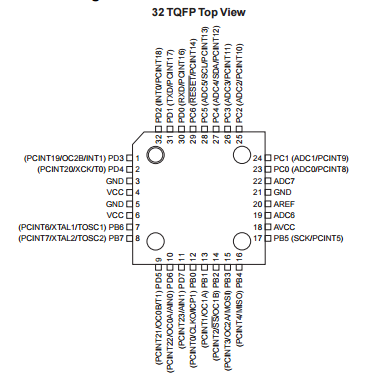
I first started my design in KiCAD, by placing down a 328 in the schematic view. I then placed necessary components such as the resonator, the ISP header and the I2C header. While placing the pin headers for extra connections, I constantly refererred back to the datasheet. The datasheet helped me visualize what pins could reach where on my board.
I then connected all of the pins on my board with wires. I used wires this time instead of global labels (thats what KiCAD calls them), primarily because I was lazy this week. If I had used global labels, I could have fixed the issues I would have in Networking because this week, I mixed up some pin locations on the I2C header compared to the board in Input Devices.
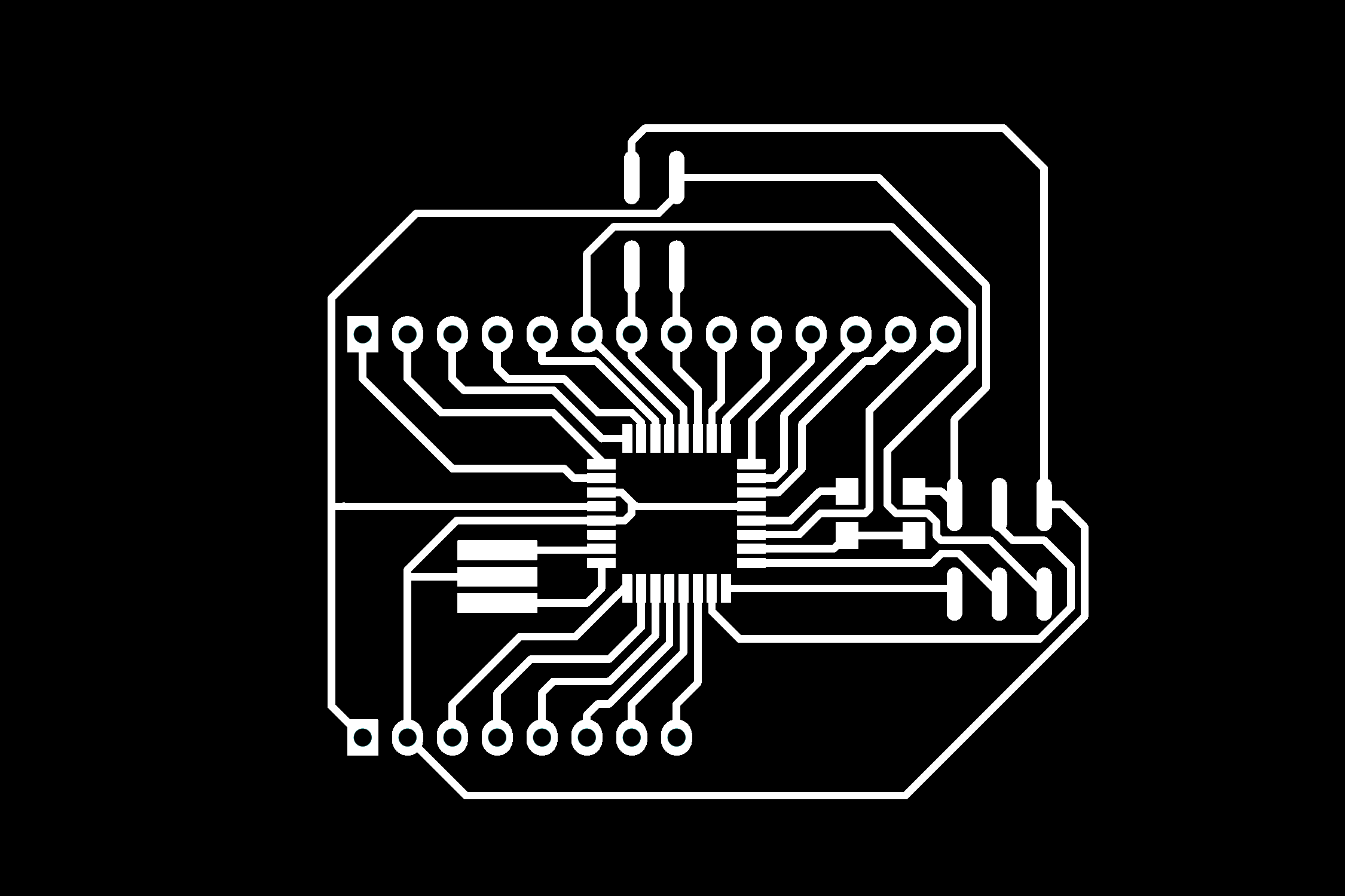
I then associated all of the parts with a footprint and created a net file that the board layout program can read. I then Opened the board layout program in KiCAD and wired everything together after reading the net file. Once again, it was really just a long puzzle similar to the three houses riddle (but with more houses and utilities). Below you can see the layout of the board before I fixed anything (it's also the PNG file I used to etch the board).
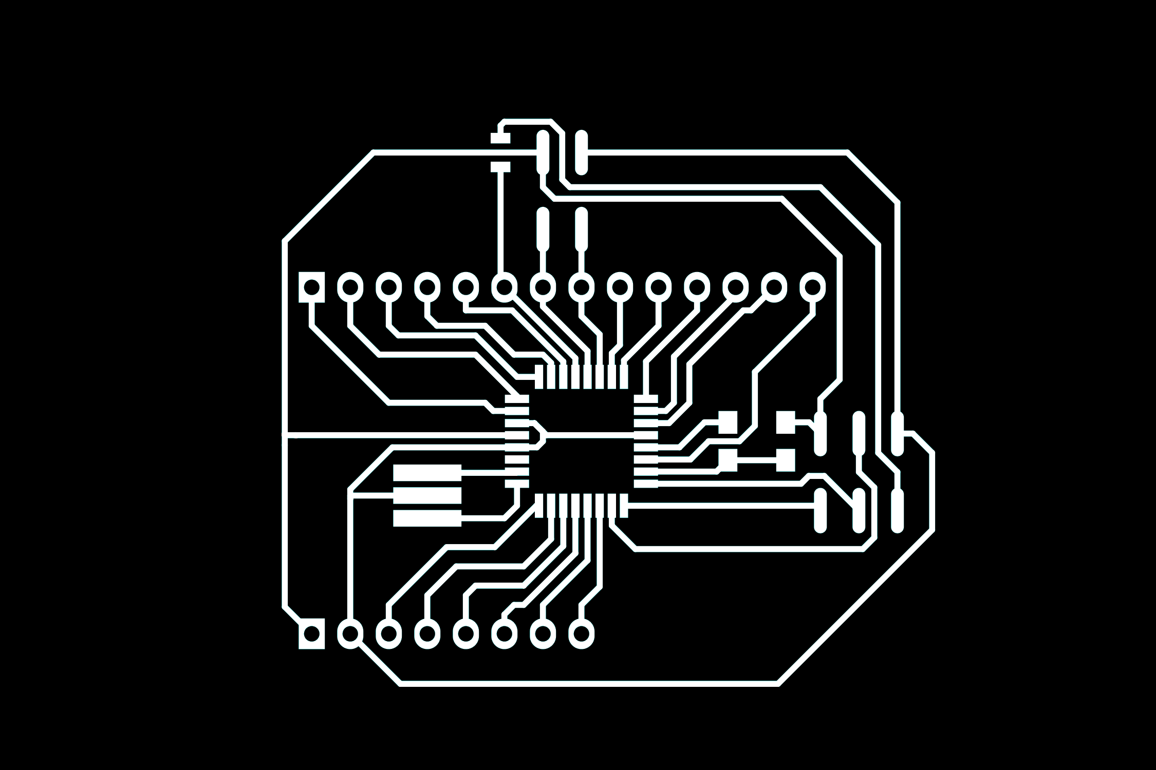
After Laying the board out, I exported the board as SVG, exporting only the Copper and paste layers. I loaded the copper layer into GIMP at 750 DPI and put the board into a new file that was the size of my blank PCB (2" by 3"). I made the background and pin holes black and the traces white (you can see this above). I then exported the image to a PNG file and then imported that PNG file into Adobe Illustrator. In AI I changed the size of the artboard to 2" by 3" (the size of my blank PCB) and centered the board layout on the artboard. I then clicked "Image Trace" to round the edges of my traces. Jagged, pixelated edges can cause traces to be shorted together by very small connection between traces. The trace button is found at the top under the toolbar.
Production
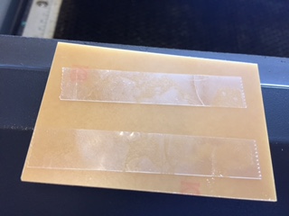
After tracing the image I took a blank PCB and placed masking tape onto the blank PCB and removed any bubbles. I then trimmed any excess tape off of the board. The masking tape acts as a resist for the etching solution. There are many other resist methods, including photo resist (requires transperencies, a toner printer, and a special board) and toner transfer (requires magazine paper, a toner printer, and a clothes iron). I chose masking tape since It allowed me to use the very precise laser cutter. I placed double sided tape onto the backside of the prepared blank PCB to hold it in place inside the laser cutter.
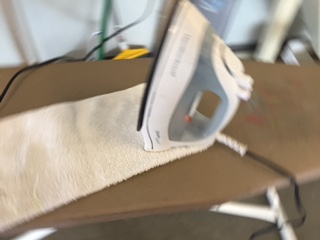
I then sent the AI file to the laser cutter, with 50% speed and 50% power. With these settings the cutter will take two passes to complete the board. Higher powers can reduce accuracy while lower speed takes too long. These settings will vary from cutter to cutter, and these settings are for the Epilog 40W cutter. After two passes, remove the board and the double sided tape and bring the board to a clothes iron. Heat the iron up and press firmly on the board. This will ensure that the remaining masking tape stays on in the solution.
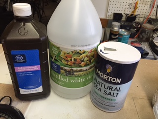
Once that is done, I prepare the solution. The solution uses a 50-50 mixture of vinegar and hydrogen peroxide. I usually add and dissolve some salt after mixing to speed up the reaction. I usually place the solution in a disposable plastic container, so that I know that the solution will not react with the container, and that I do not need to worry about any contamination in my food later on. Glass containers are also usable, and are useful if you wish to heat the solution up, which also speeds up the reaction.
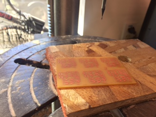
I then dunk the prepared board into the solution. Depending on the strength of the reactants used and many other variables, the board can be finished in anywhere from 10 minutes to 12 hours. I do not reccomend scrubbing the board, since it can damage the resist, ruining the board. When the board is done I rinse off the board and neutralize the solution and dispose of the solution safely. This is a good time to remove the resist. I then take the finished board to a drill press and use a drill bit that is the size of the holes on my board, usually 1mm in diameter, and drill the oles out. Sometimes I trim the edges of the board, but this time, I was lazy and didn't do it. The photo is of the Input Devices boards, but the concept is the same.
I can now solder all of the components of the board. I first gather all of the components I will need. I then usually sand off any oxidation on the board with a fine grit sand paper or fiberglass pen. I solder the components from lowest to highest in height and from least sensitive to heat to most sensitive to heat. I usually do the through-hole components last, since they can create an uneven soldering surface.
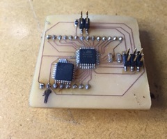
The board is now ready to program.
Programming
Programming the board was very difficult. I needed to modify some of the files controlling the way the Arduino IDE handles programming and translation. The issue arose when I tried to program the board the fisrt time. The IDE told me that I was using the wrong processor.
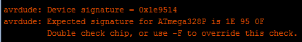
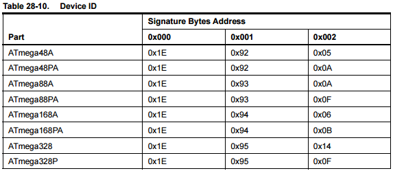
It turns out that our Fab Lab had ordered (a long time ago) the ATMega328 instead of the 328P. The 328P is a diferent version of the 328 with the same everything except power consumption. The boards use two different device signatures, which was telling the IDE that I was using a different chip than what the library thought I was using, a 328P. These signatures can be found on the datasheet.
I tried to locate board packs that would allow me to use the 328, but I could only find packs for the 328P. I then found advice on the arduino forums that said that I needed to modify the avrdude config so that the board would be recognized by the IDE as a 328P. The steps can be seen in the image below.
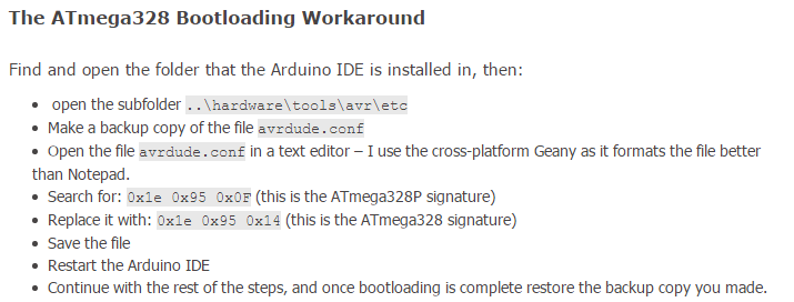
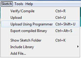
I strongly reccomend using wordpad to open the config, since notepad is terrible at formatting the document. Once you have located and opened the document in wordpad, search for the word "328P" and locate the device signature and change it to "0x1e 0x95 0x14". The IDE should now recognize the board, no matter what library you use. I tend to use the default Uno board and I upload programs using the "upload using programmer option".
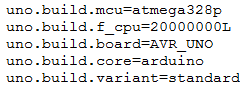
If you are using a 16 MHz crystal, you don't need to do anything else to get the board to work properly, however I used the 20 MHz crystal so I needed to make a minor change to the boards.txt file found in Arduino\hardware\arduino\avr. I opened the file in notepad and changed the frequency to 20 MHz.
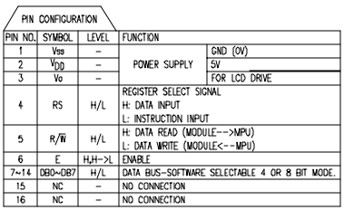
To learn how to program the 328 to drive an LCD, I looked at the example code provided with the Arduino IDE, and also at the datasheet for the LCD I was using. The code used to run the LCD was not very straightforward, but was usable enough. The datasheet gave me the pinout of the LCD, which would be helpful when I hook it up to the board.
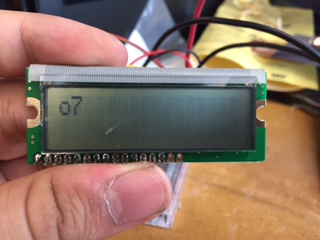
I had the program display some simple text on the LCD: "o7", which looks like a person waving. Much simpler than "hello world" Unfortunately, I have no screenshots of the code or access to it, since the file has since been corrupted. The code started the LCD, write "o7" and move the cursor to the next line.
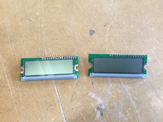
There are some things I didn't know at the start of the project that I learned after programming the board. One of them is that I needed to actually connect the R/W to ground, not just leave it floating. You also need a potntiometer to vary the screen contrast. I also learned (the hard way), which power pin is which on my board. I fried two LCDs before realizing that I was connecting the power around the wrong way.
Once everything was hooked up correctly, I then had a working LCD for my final project.
 - fixed file for the board, no differences from the one I used here except for one less resistor and a changed I2C Header. The changes make this board compatible with other I2C boards I have made.