Networking and Communication
design and build a wired &/or wireless network connecting at least two processors
Planning for this week:
Build a new board including ATTiny 45
Get work it using serial on Arduino IDE
2. Build a network using light-sensor board and servo-board
When I did a micro-controlled board including a phototransistor I decided to introduce a 4-Pin bus in order to communicate it with the board I try to do this week.
3. Design a wired network
Build a new Fabduino ( Satshakit )
Design and build a I2C communication using two Fabduinos ( Satshakit )
4. Testing a network in Grasshopper
Connect various boards using Firefly in Grasshopper.
5. Decide and Design the final project
Check the issues I have to solve in order to arrange a network for my final project
2. Build a network using light-sensor board and servo-board
Plan A: design a networking between both boards using the bus as Rx-Tx interface.
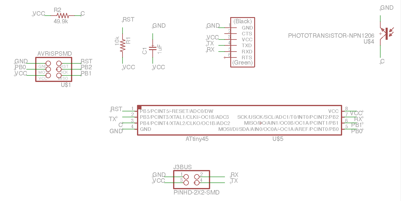
Scheme of the MC board including phototransistor and PinHD
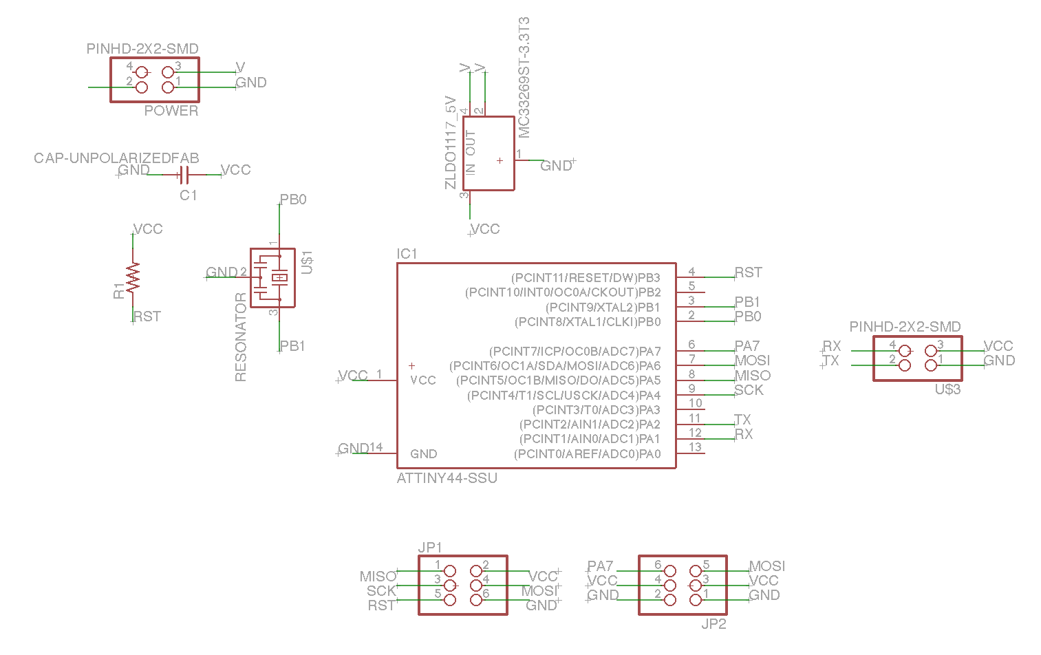
Scheme of the MC board including servo cotrollers and PinHD
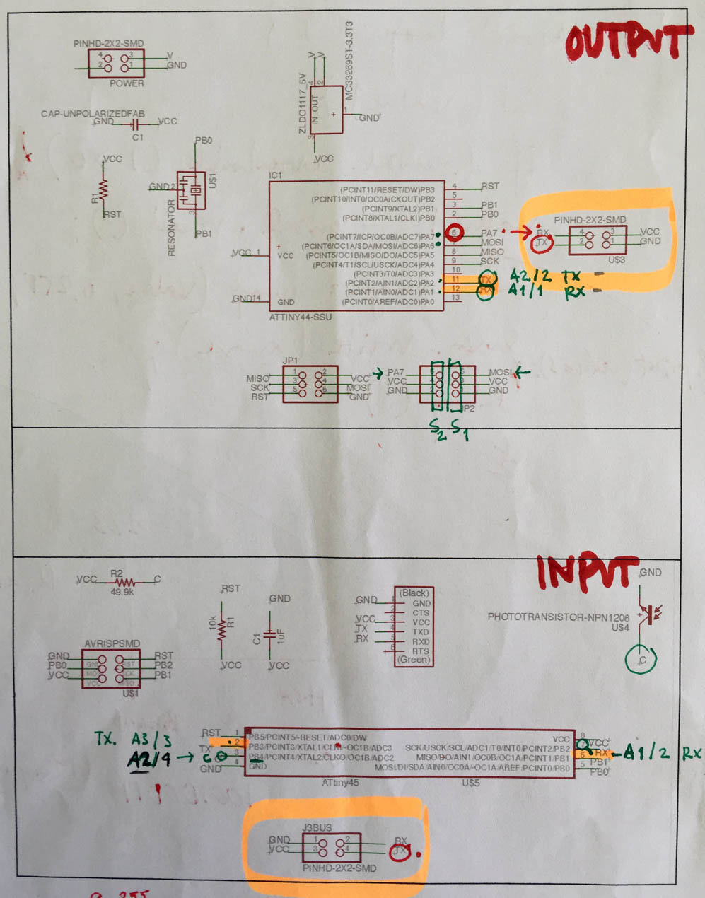
Relationship between the schemes and the correspondence with the proper Arduino pins.
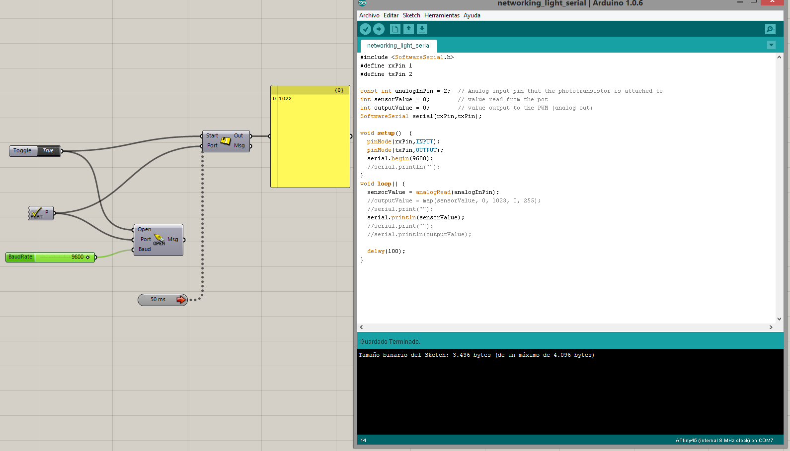
Below, programming the boards.
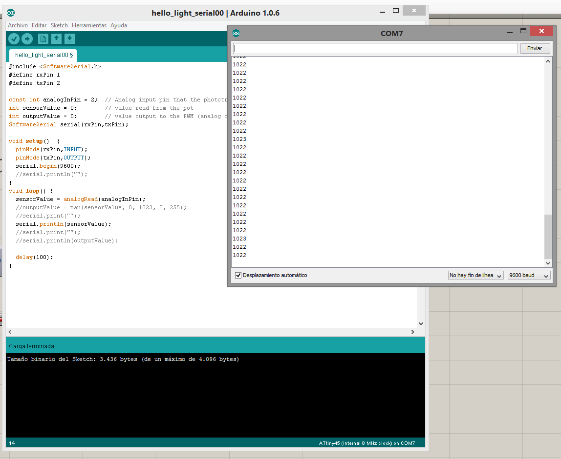
Arduino sketch and lecture of the sensor via serial.
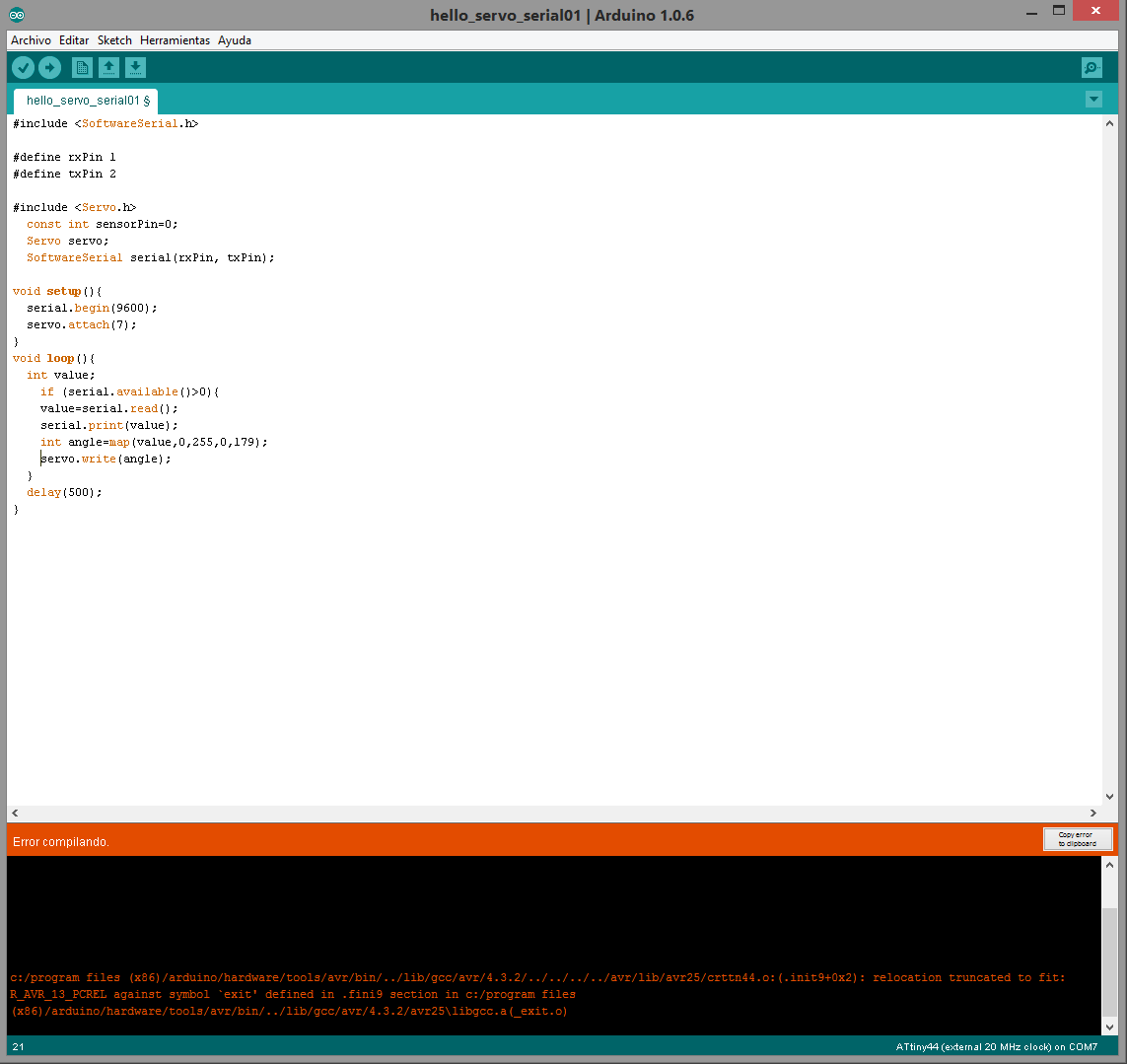
First problem! it is not possible to compile the skecth. I cannot understand what the problem is focused. First I thought that could be the clock speed because on the Attiny 45 board there is an internal 8Mz while on this one there is an external 20Mz one.
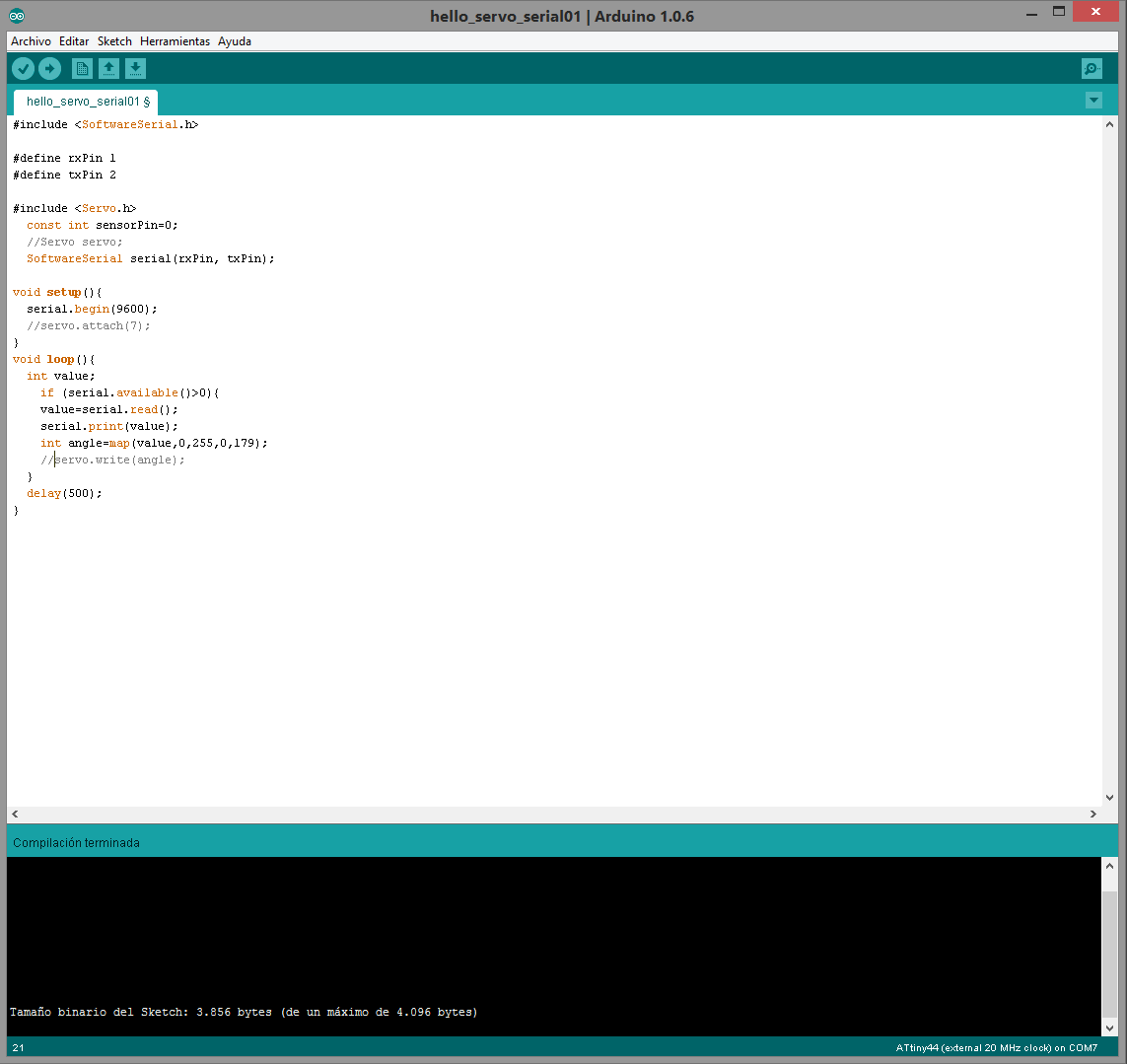
In fact, if the servo library is not charged, the compilling works fine. So I cannot arrange this kind of network between this boards. Really, in this kind of network I have been thinking that my final project could be based and I realized that it will not be possible.
3. Design a wired network
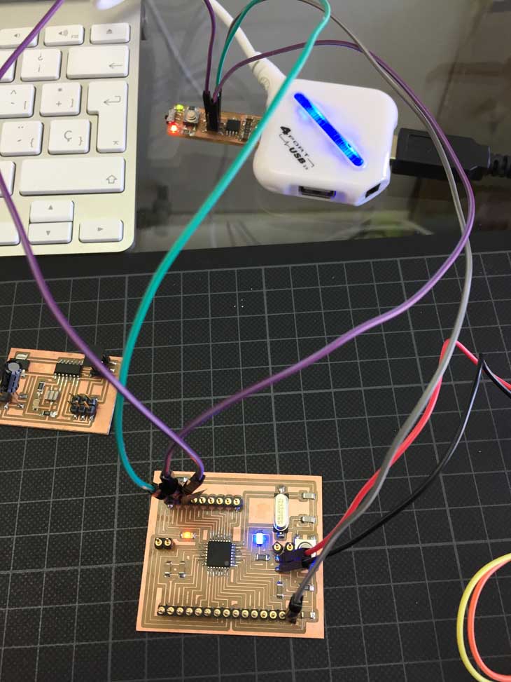
I need a Plan B!, So I have tried I2C communication using two Fabduinos ( Satshakit )
I made the first one a couple of weeks ago and I just made the second during this week. I choose the Satshakit multicore design in order to take advantage of the additional GND-VCC outputs that will be useful when I have to feed the servos for my final project.
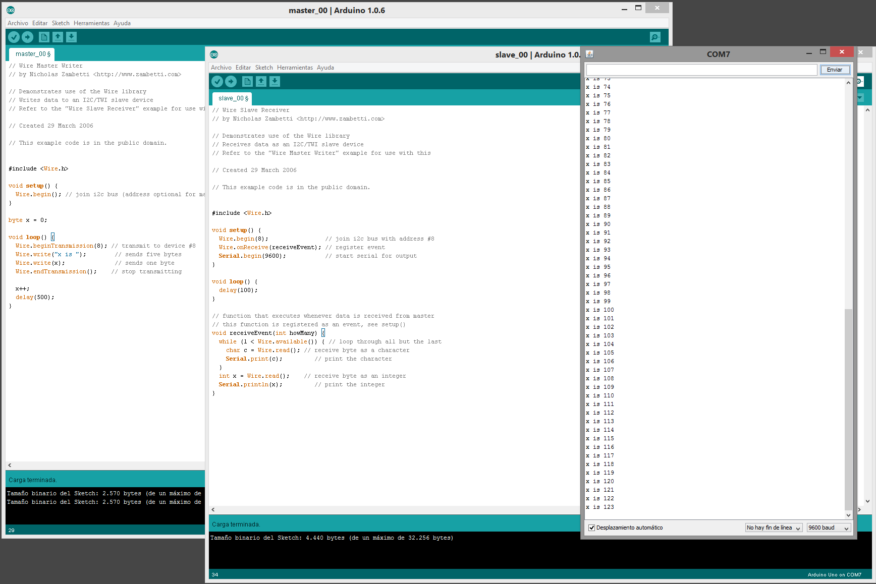
I tried this kind of communication by using the Arduino Master Reader/Slave Sender configuration. For this purpose, there is necessary the use of the Wire.h library.
The I2C protocol uses two wires to send and receive data:
Serial clock pin (SCL) Arduino pulses at a regular interval
Serial data pin (SDA) through this one data is sent between the two devices
As the clock line changes from low to high (known as the rising edge of the clock pulse), a single bit of information - that will form in sequence the address of a specific device and a command or data - is transferred from the board to the I2C device over the SDA line. When this information is sent - bit after bit -, the called upon device executes the request and transmits its data back - if required - to the board over the same line using the clock signal still generated by the Master on SCL as timing.
Because the I2C protocol allows for each enabled device to have its own unique address, and as both master and slave devices to take turns communicating over a single line, it is possible for your Arduino board to communicate (in turn) with many devices, or other boards, while using just two pins of your microcontroller.
But, what is I2C?
Synchronous serial communication describes a serial communication protocol in which "data is sent in a continuous stream at a constant rate."
Synchronous communication requires that the clocks in the transmitting and receiving devices are synchronized – running at the same rate – so the receiver can sample the signal at the same time intervals used by the transmitter. No start or stop bits are required. For this reason "synchronous communication permits more information to be passed over a circuit per unit time" tan asynchronous serial communication. Over time the transmitting and receiving clocks will tend to drift apart, requiring resynchronization.
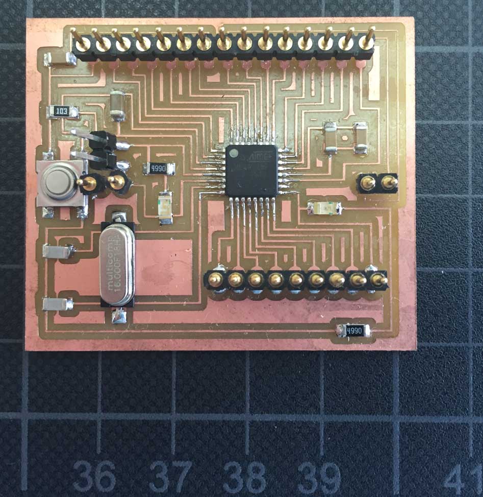
In this case I decided to try satshakit multicore
After some problems milling the board I got my second Fabduino, probably I will use this board in my final project because it is recognized as an Arduino UNO and it does raise no problem working in Grasshopper. But I suspect that more power outputs might be necessary.
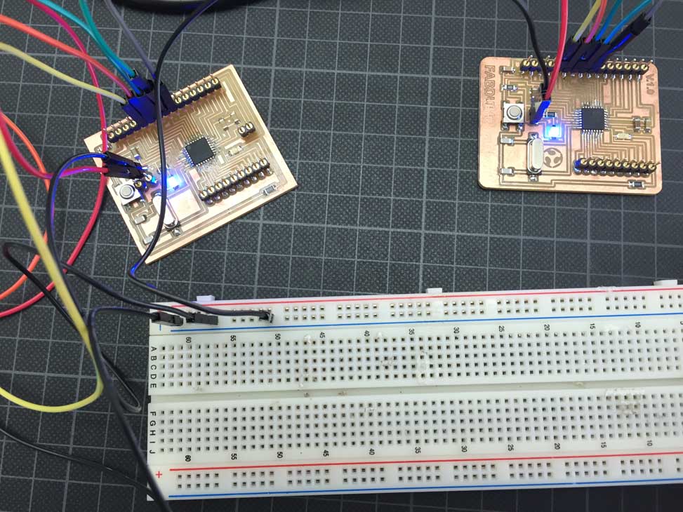
Two satshakits are talking...
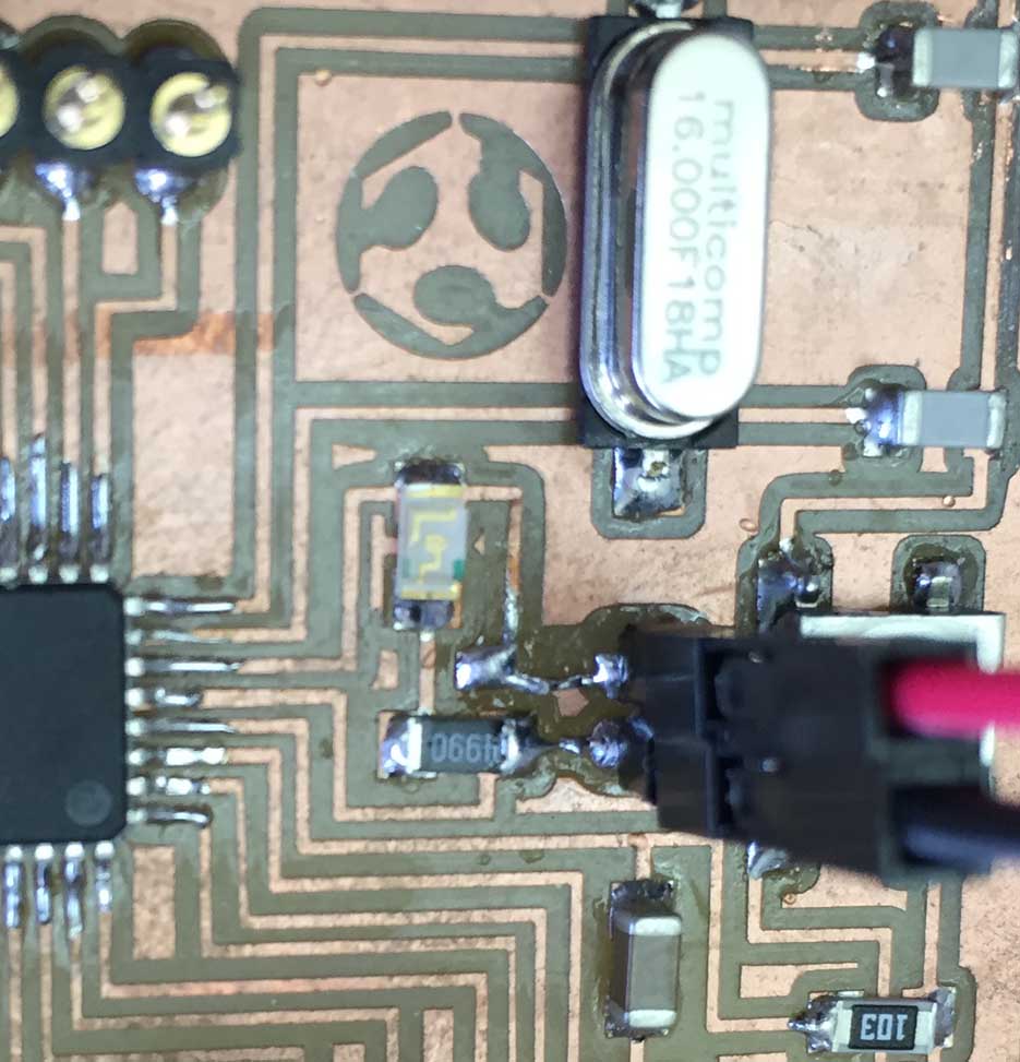
CRISIS!! Due to the fact that I used some kind of connectors which are sligthly fitted to the wires, I broke the connectors when I was trying to switch off the wires. Even the copper ways left from the board...
After the resulting panic episode I achieved to arrange this bloody mess, It don´t look very fancy but it works!
5. Decide and Design the final project
I have take advantage about the assignment for this week in order to check the issues I have to solve in order to arrange a network for my final project
One of my main objectives is to use Grasshopper as much as possible, so I have tried to do a networking communication between two boards using FireFly. In this way I connected the light sensor to one of the Fabduino-Satshakit boards and the servomotor to another one in other to allow the control of the servo through the data received from the sensor using the grasshopper environment as a bridge.
Actually, it would be done using only one Fabduino but turning around this week subject I tried to make a networking using two boards.
Serial reading of the sensor using Grasshopper
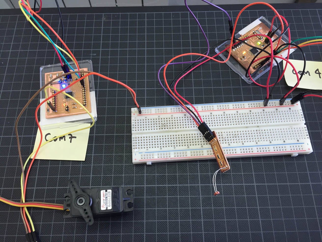
The arrangement and communication between two boards is possible using Firefly. Here, the ligth-sensor sends data through the COM4 board to the COM7 one where is attached the servo-motor.