Input Devices
Add a sensor to a microcontroller board that you have designed and read it.
During the semester I have been working with different kind of sensors and boards. Bellow there are the documentation of all of them.
1. Photoresistor (week 11)
I have learnt how the sensor works. Is a very simple circuit, but is the only I need in my final project.
2. Hall-effect (week 13)
A trial on the way to measure angular distances.
Build a board including ATTiny 45
Read it using serial on Arduino IDE
Read it using FireFly on Grasshopper
3. Phototransistor (week 14)
A trial on the way to measure angular distances.
Build a board including ATTiny 45
Read it using serial on Arduino IDE
Read it using FireFly on Grasshopper
How this sensor works using a micro-controlled board. Besides it integrate the way tio talk with another micro-controlled boards.
This week I have been trying to arrange how my final project would be communicated and which could be the correct way to do it in order to control the movement of the responsive element.
It would be focused in two different directions:
A. Measuring the amount of light power the surface of the object is able to receive. This question is particularly relevant if the improvement of the capacity to gain or lose energy is the ultimate objective. In this way the sensor should be such a kind of power gauge or power meter.
B. Measuring the intensity of light impact. Only related with the orientation of the deployable element its opening would be controlled, so it should be opened when the light amount was low and be closed when this one was high.
I decided starting through the second approach. Actually both of them would be related but I think that the second one could be an easier trial by now.
First I have documented how a Photoresistor works. So we can say that a Photoresitor or light dependent resistor (LDR) is a light-controlled variable resistor. The resistance of a photoresistor decreases with increasing incident light intensity. The electric current flowing through this component is proportional to the intensity of a light source. A photoresitor can be applied in light-sensitive detector circuits, and light and dark activating switching circuits/systems.
Besides there is another kind of light sensor group called phototransistor, a bit more complex device but more accurate. In order to determinate what kind of photo sensible device should be more suitable I decided to probe both of them, measuring the values.
1. Phothoresistor
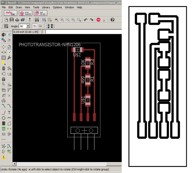
Design of a board. Inspired by the circuit designed using breadboard I have made my own board in order to support either the photoresistor as the phototransistor.
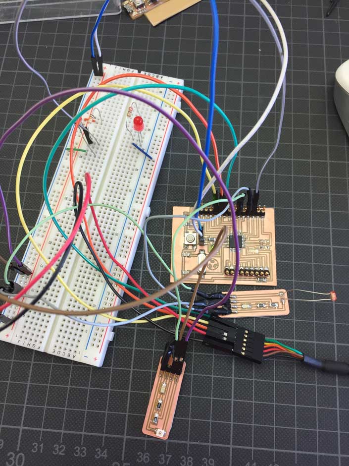
Reading three sensors simultaneously.
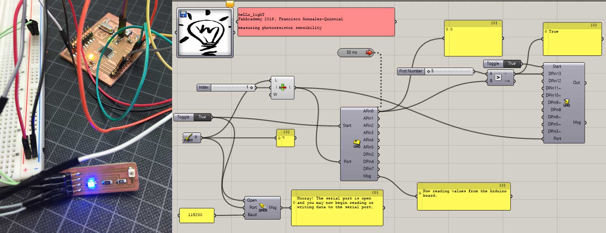
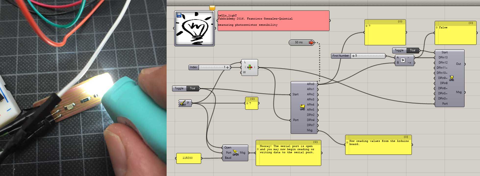
Testing the board using Firefly/Grasshopper. Measuring the valued offers by the sensor it could be interpreted and proccesed in any way you want. Here if the sensor value drecrease the LED turns on and reversely if the value grows up the LED turns off.
2. Hall Effect sensor
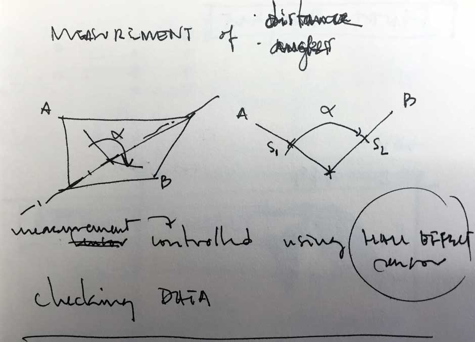
I need a sensor which is able to mesure the angle that two planes form. So I have been working with this kind of sensor in order to know how I could adapt the measurement into angular distances. Finally I gave up it because this kind of sensor acts more as an interruptor than properly a sensor.
By default, the ATtiny’s run at 1 MHz. You can configure them to run at 8 MHz instead, which is useful for faster baud rates with the SoftwareSerial library or for faster computation in general. To do so, once you have the microcontroller connected, select “8 MHz (Internal)” from the Tools > Clock menu. (In Arduino 1.0.x, select the appropriate 8 MHz clock option from the main Tools > Board menu.) Warning: make sure you select “internal” not “external” or your microcontroller will stop working (until you connect an external clock to it). Then, run the “Burn Bootloader” command from the Tools menu. This configures the fuse bits of the microcontroller so it runs at 8 MHz. Note that the fuse bits keep their value until you explicitly change them, so you’ll only need to do this step once for each microcontroller. (Note this doesn’t actually burn a bootloader onto the board; you’ll still need to upload new programs using an external programmer.)
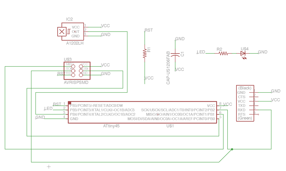
Eagle scheme
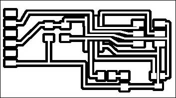
Milling sketch
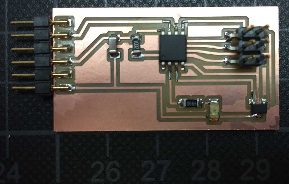
Finished board
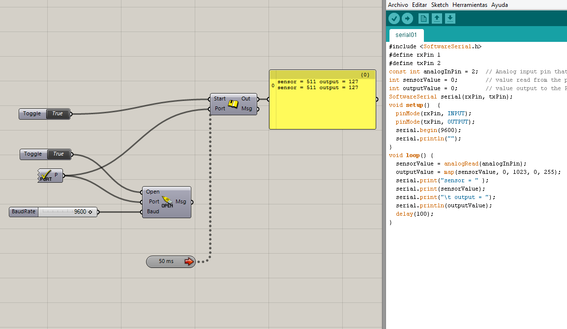
Reading data using serial interface both in Arduino as in Grasshopper.
3. Phototransistor
This exercise thought me how the sensor work and how the micro-controlled board data can be read using serial communication on Arduino. It is as simple as reading them on Grasshopper.
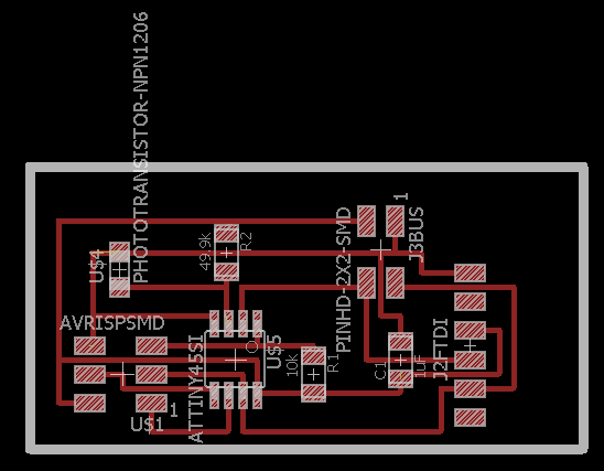
Eagle design Board
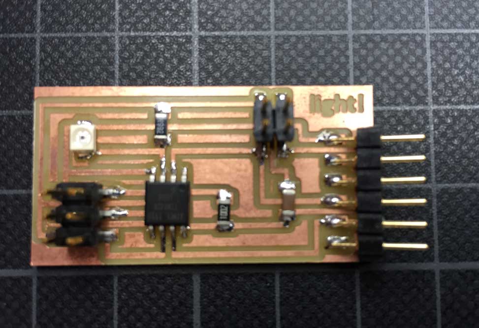
Board finished
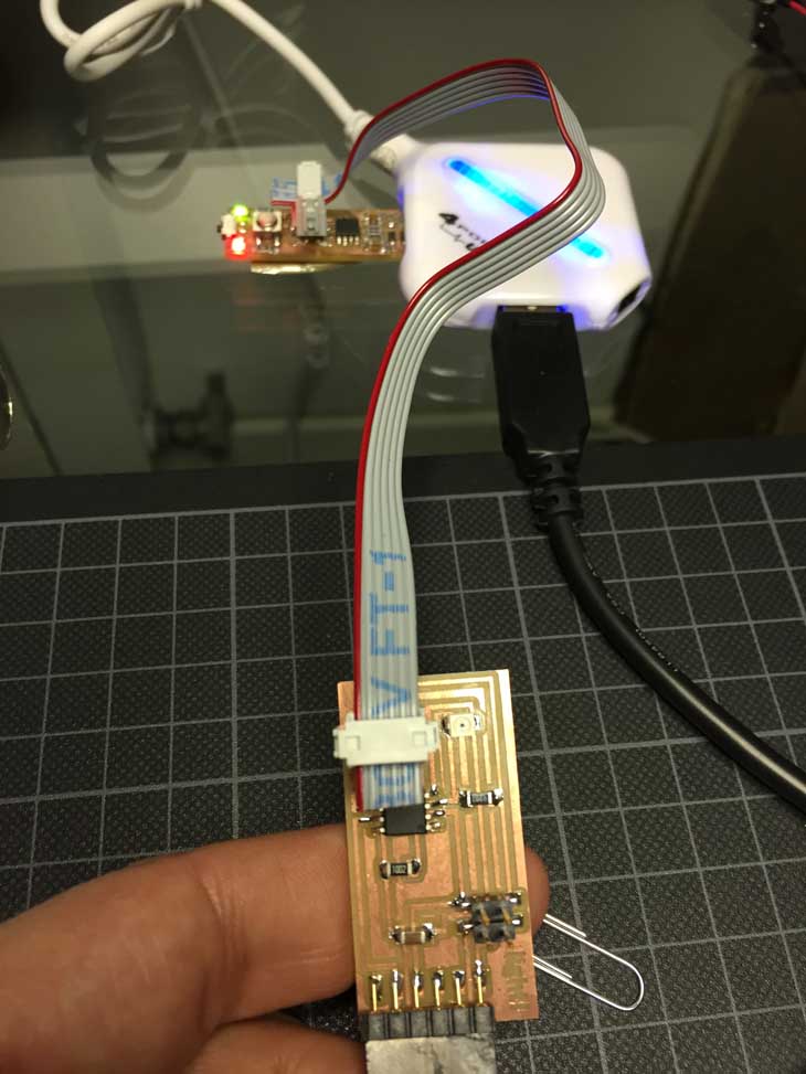
Burning the board using FabISP
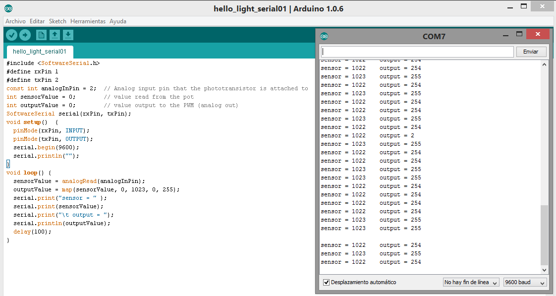
Lecture of the sensor using Serial in Arduino