Networking and Communications
Note: My code and files and a lot of photos can be found here in the Week 14, "Composites" folder. I am only posting low resolution photos on this page. Week 15, Networking
Force directed edge bundling a visualization of air travel paths in the USA, Alexander Haase
I2C or Inter-Integrated Circuit bus
Because the milling of my final project was taking so long, I was the last person in our Fablab team group to get started with Networking. I didn't see it at the time, but it was a real advantage. I had lots of people I could ask questions to and get advice. At this juncture I was not using any Networking in my final project, so I decided to work on this section last.
Assignment- Design and build a wired and/or wireless network connecting at least two processors.
I decided to build a wired network that would work with the Modified Satshakit Arduino I had already built for my output assignment in Week 13 Output
From the list on the Networking Communications page at Fab Academy, I chose to learn about I2C networking, in this case because time was running short and I needed to be able to ask questions of my teammates around me.
Step 1: Educating myself on I2C networking.
Starting from exactly ZERO knowlege of this subject I had a lot to learn. The first place I went to do this was I2C bus users Manual and read the manual. This was a greatly informative excercise and I learned a great many things.
Salient Points taken from the Manual.
1. Philips Semiconductors (now NXP Semiconductors) developed a simple bidirectional 2-wire bus for efficient inter-IC control. This bus is called the Inter-IC or I2C-bus
2. Only two bus lines are required: a serial data line (SDA) and a serial clock line (SCL).
3. Serial, 8-bit oriented, bidirectional data transfers can be made at up to 100 kbit/s in the Standard-mode, up to 400 kbit/s in the Fast-mode, up to 1 Mbit/s in the Fast-mode Plus (Fm+), or up to 3.4 Mbit/s in the High-speed mode
4. Each device connected to the bus is software addressable by a unique address and simple master/slave relationships exist at all times; masters can operate as master-transmitters or as master-receivers.( This would be very important when I set up my network.)
I then went here and read the tutorial. Robot Electronics I2C Tutorial
I also went to the Sparkfun Page and did a little more research Sparkfun I2C Tutorial
I liked this page because it really helped me understand the avantages of the I2C network.
The sections on boards with different signal levels was especially interesting to me becaue it talked about pull up resistors when the votage was different. I would use this later in my network. Here is that section from the page I found really helpful.
"Since the devices on the bus don’t actually drive the signals high, I2C allows for some flexibility in connecting devices with different I/O voltages. In general, in a system where one device is at a higher voltage than another, it may be possible to connect the two devices via I2C without any level shifting circuitry in between them. The trick is to connect the pull-up resistors to the lower of the two voltages. This only works in some cases, where the lower of the two system voltages exceeds the high-level input voltage of the the higher voltage system–for example, a 5V Arduino and a 3.3V accelerometer. If the voltage difference between the two systems is too great (say, 5V and 2.5V), SparkFun offers a simple I2C level shifter board. Since the board also includes an enable line, it can be used to disable communications to selected devices. This is useful in cases where more than one device with the same address is to be connected to a single master–Wii Nunchucks are a good example."After doing reading these tutorials I then scheduled a meeting with Tom Dubick and went over with him I2C in a 30 minute tutorial so that my understanding of the material was bolstered and confirmed. Tom did a great job of further explaining this network to me.
Step 2. Building my Network
I now had to build my network. As I was using the modified Satshakit Arduino I made and several Arduino Unos. I went to the Arduino page to start that tutorial.
Arduino Master Writer TutorialI followed the tutorial.
Now that I was actually building a network, I really appreciated the great thing about I2C networking is the wiring. It is only two wires the SCL (serial clock) and the SDA (Serial Data)
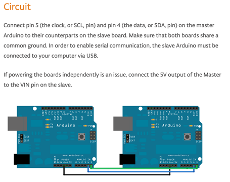
IC2 Network Building Process 1. Wire the arduino boards, The SCL pins and the SDA pins to align with the counterparts on the other boards.
IC2 Network Building Process 2. I designated one Arduino Master and one slave and wired it as the diagram below shows. It is critical that the two boards share ground. Here is a screen shot of that diagram from the web tutorial.
IC2 Network building Process 3. Code- For this I needed to open up a few examples in Arduino. I was going to be using a program for the master and a program for the slave. Here is what I did.
Programming the Master
Load Arduino software.
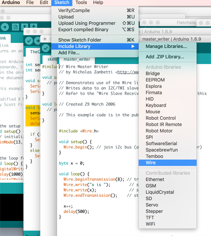
As shown above Select Sketch>Include Library>Wire.
As shown above open File>Examples>Wire>master_writer
Connect the master arduino to the computer with USB programming cable.
Verify Sketch
Check under Tools for the Uno Board.
Make sure the port is correct
Confirm that the port is connected to your arduino
Run master_writer Program.
Disconnect the master arduino from the computer.
Programming the Slave Reciever
As shown above Select Sketch>Include Library>Wire.
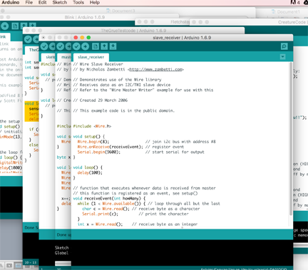
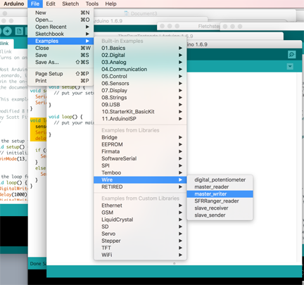
As shown above open File>Examples>Wire>Slave reciever
Connect the slave arduino to the computer with USB programming cable.
Verify Sketch
Check under Tools for the Uno Board.
Make sure the port is correct
Confirm that the port is connected to your arduino
Run Slave Reciever Program.
Go to tools and open the Serial Monitor
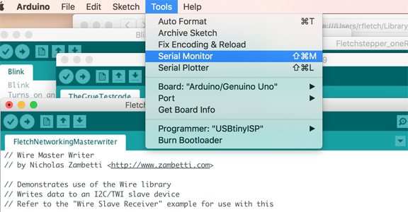
If it is networking, the serial monitor should be printing out a value for x, up to 256. Mine was doing exactly that, I had networking on two Arduino's working!
Here is a video of my first network using I2C
After I got it working, I went in and changed a variable in the Slave example
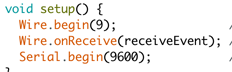
and Master example from 8 to 9
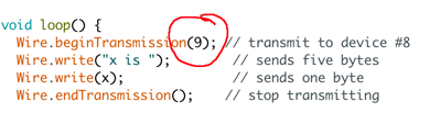
The video can be seen below.
Integrating my Satshakit Arduino into the I2C Network
Now it was time to integrate my own Fabduino into the network.
The big difference now was that I would have to include pull up resistors because they are not included in the Satshakit Modified Satshakit Fabduino that I had built earlier.
Here is a representation of my modified board with an extra ground pin
The eagle board files can be found here.
Modified Satshakit Files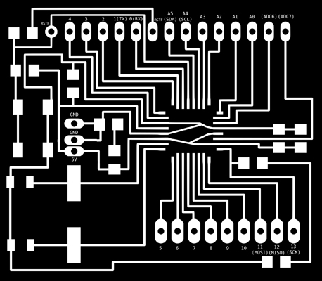
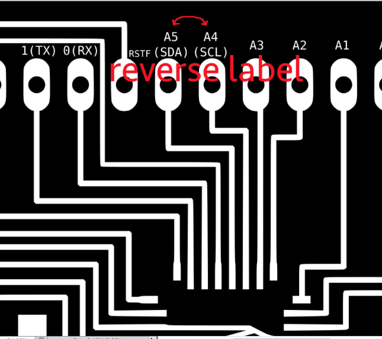
Our lab did find one problem with the Satshakit Arduino labeling When we were trying to network. The SDA and the SCL pins seem to be labeled backwards. When we connected the pins correctly they networked just fine.
Connecting my Fablab Arduino - Satshakit Arduino to a commercial Arduino. We will to use two 4.8k pull-up resistors (Once again, this is important, because while included in the Arduino Uno, the Pull up resistors are not included in the Fabduino I used. Pull up resistors allow for the signal to be pulled back up after it drops after the reading between the two boards and communicating with each other. )
For this example, I made my Satshakit Arduino the slave.
I connected the modified Satshakti Arduino's SCL, SDA, Ground, and VCC pins to a breadboard noting the lable change I showed above.
I connected the FTDI power and ground to the breadboard.
I connected the FTDI TXD, RXD, and RTS to the Satshakit Arduino to allow programming of the Slave Reciever sketch
I connected the Master Arduino SCL, SDA, VCC and Ground pins to the breadboard
I used one 4.8k resistor to connect the master SCL to the Satshakit SCL.
I used another 4.8k resistor to connect the master SDA to the Satshakit SDA.
I connected the master ground and vcc to the ground and vcc of the Satshakit and FTDI.
I checked that the port is correct, under Arduino tools, to the FTDI and the Satshakit arduino
Now I uploaded Slave Receiver file to the Satshakit arduino.
Open serial monitor if it is not already.
The serial monitor should show x is ... an integer that increasing up to 256.
Success! Below is the video of my Satshakit Arduino networking with an Arduino Uno.