Electronics production
15_02 to 20_02 2017
Assignment:
1. Make the Fasbisp in-circuit programmer by milling the PCB
04_Week work:
My goal in this week is This week we learn how to diagram our own FabISP on Eagle software, router de FabISP and late soldering the components.
Sofware:
Eagly, Fritzing, designspark, flatCAM 8.5, Imagetogerber v1.1, bCNC.
Machines:
Mini CNC engraving machine.
Tutorials:
Tutorial 4
Components:
1 ATTiny 44 microcontroller/ 1 Capacitor 1uF/ 2 Capacitor 10 pF/ 2 Resistor 100 ohm/ 1 Resistor 499 ohm/ 1 Resistor 1K ohm/ 1 Resistor 10K/ one 6 pin header/ 1 USB connector/ 2 jumpers - 0 ohm resistors/ 1 Crystal 20MHz/ 2 Zener Diode 3.3 V/ 1 usb mini cable/ 1 ribbon cable/ two 6 pin connectors
Drive files:
Download week work
Archive files:
fab.lbr /
fabisp.brd /
fabisp.sch /
energy_regulator.brd /
energy_regulator.sch
energy_regulator.png
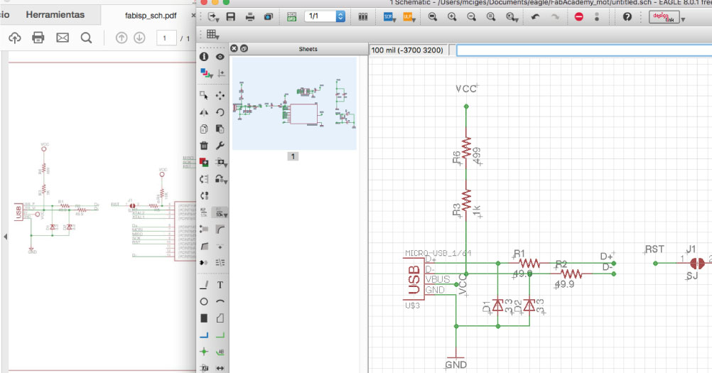
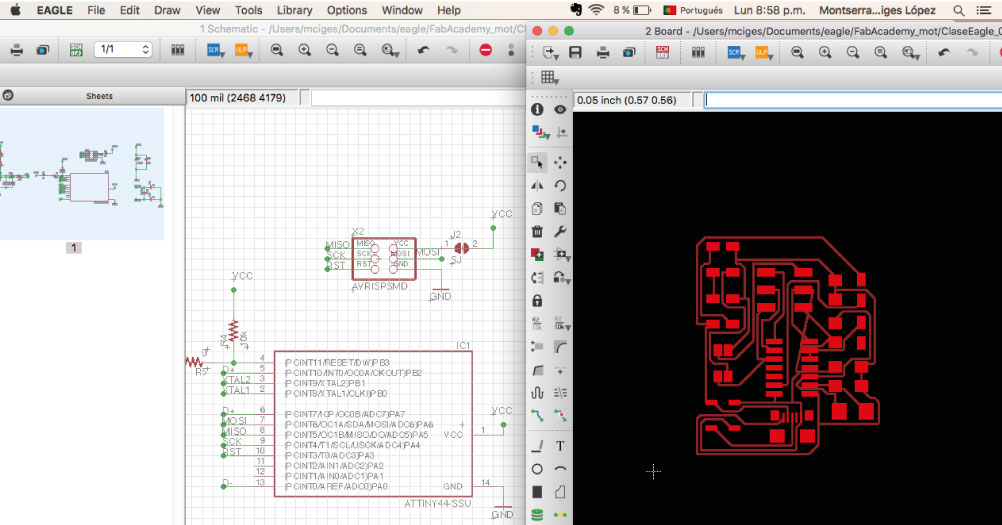
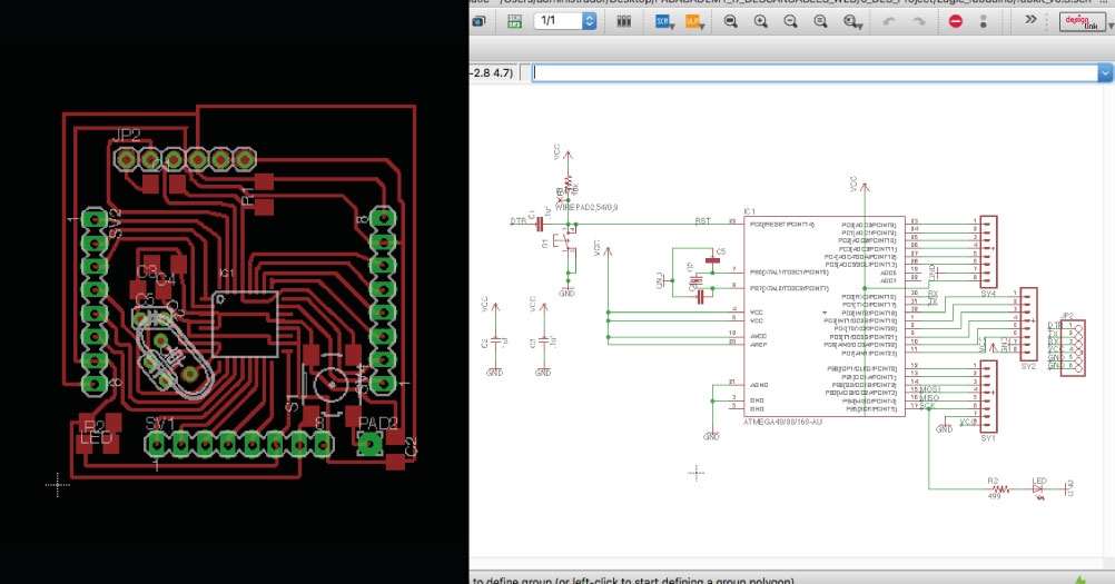
Eagle:
We used a software by Autodesk called Eagle to design the circuit boards. With the basic knowledge from the previous class, we could understand schematic diagrams of circuits. This was vital to be able to make our own schematic diagram in Eagle.To make the schematic diagram in Eagle, we uploaded a library of components for the Fab Academy with the specifications and requirements that we needed. Drag and drop the file into the library section of the control panel.
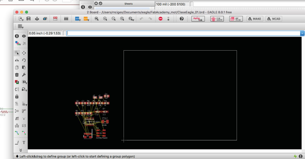
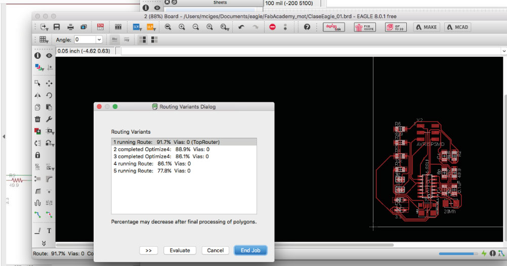
Autoroute:
You can trace the routes manually or with the Autorute button. The goal is that 100% of the connections have a logical and physical route. The autoroute is not the best opcion normally, but helps to have a first tentative.
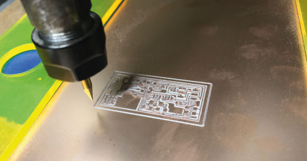
FabISP:
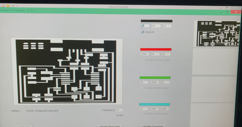
Using a milling machine, we made PCB (printed circuit board). The machine reads a language called GCODE that contains a series of commands for the machine to trace the places were it moves. To generate a GCODE, it is necessary to import the board diagram made in Eagle to a software called FlatCam. But first for the process of creating the files with the instructions for the milling machine, FlatCAM was used, but before that, the png file was converted to a gerber file with imagetogerber.jar.
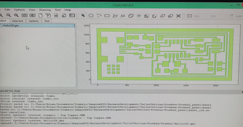
Gerber + flatcam:
The gerber file created is imported into FlatCAM. The traces are redrawn from the gerber. The first step is to set the units for the project, in our case is mm, after, configure the tool diameter to 0,3 mm for the isolation route, then generate geometry object.
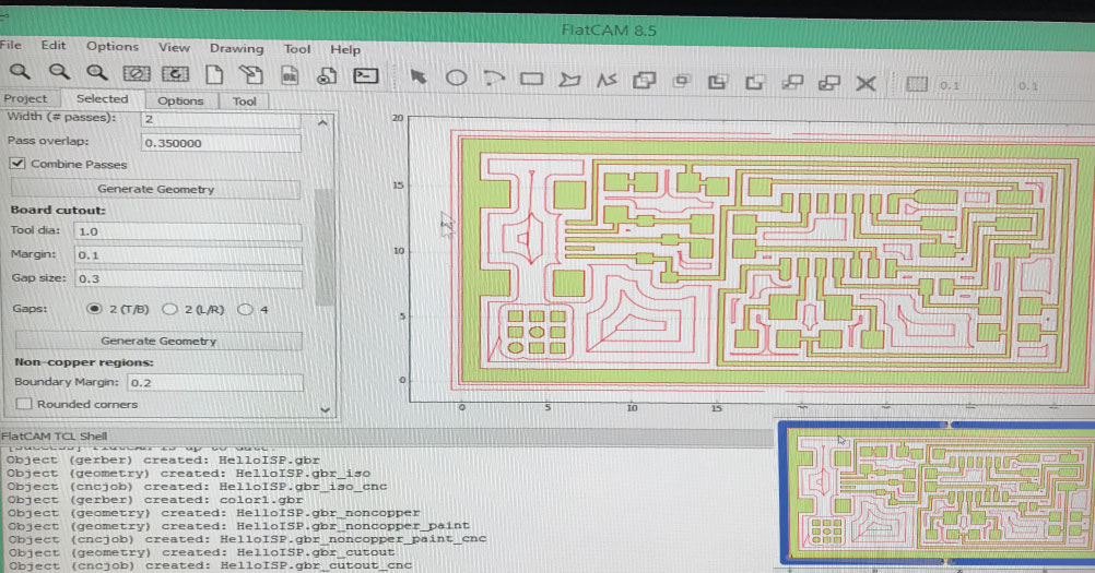
Flatcam:
Once the geometry object is created, you can inspect that the route goes parallel to all the pcb routes, effectively isolating them. When the button generate is clicked, it creates the g-code for the isolation route of the pcb. It must be saved with .nc extension.
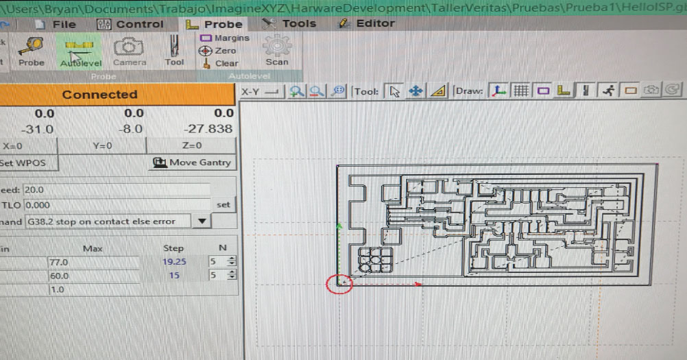
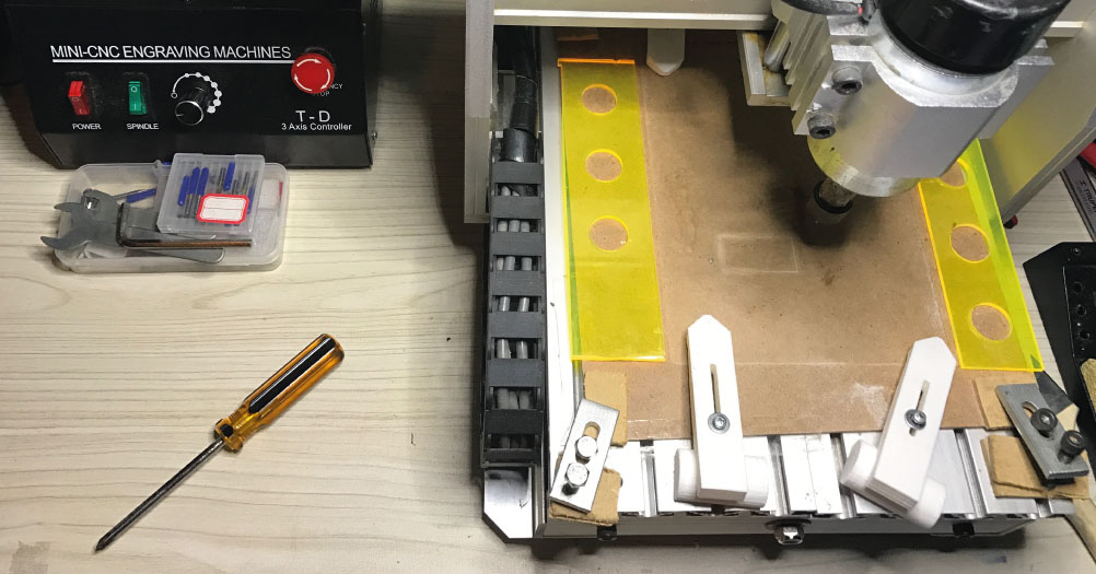
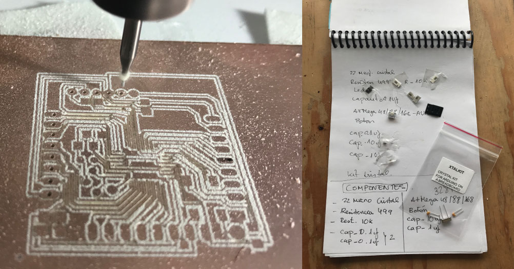
Millie machine:
The plate is held by means of presses and is also supported by blue masking tape. For this machine can be made a measurement of the height of different points of the surface using an electrical contact. Once the plate is clamped and aligned, a software called bCNC is used, which interprets the previously created files and sends the gcode to the machine, we select the origen of the machine, and we start to router our board. T
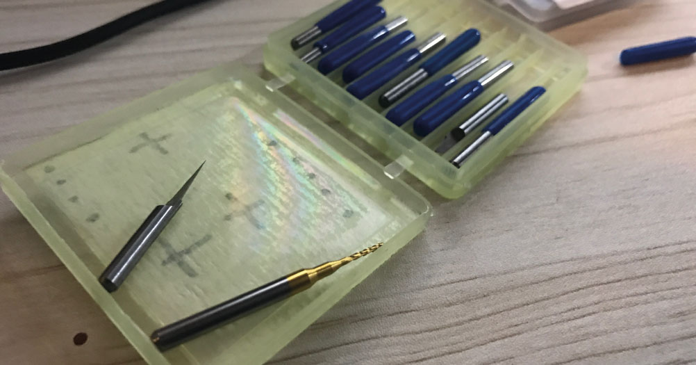
Routering and drilling:
There are diferents drills for diferents momentes of the process, one more thin for router and the second bigger for drilling. First in aproxmidly 30 min, the firt process finish to router. The second process is so fast to cut de board, but you have conservate the same origin

Board 1, Failured:
We had a 20MHz resonator but it did not fit the routes in the board, and the one that fit, already has internal capacitors. So we modified the board traces. We cut the two capacitor traces to ground by cutting on the pink marks, then, connected the resonator to the points required.
After performing all the process of routing and cutting, weld all the components to the board, being my first time, it has been somewhat complex to accustom me to the small components. Finally, when I did the test, I realized that there was a connection failure on one of the tracks, so my colleague Juan Carlos helped me make a bridge to remedy the error.
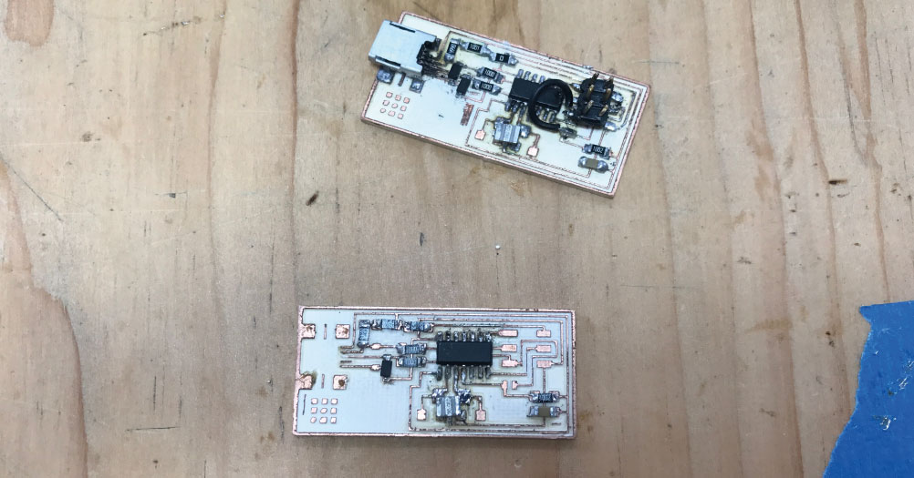
Board 2, Success :
I decided to create a second board, since the ISP is going to use it in the near future, I would rather do all the work and have a more reliable board. This time when repeating the process, I have had more ease in welding and the process has been much faster. Finally I got a better result and work.

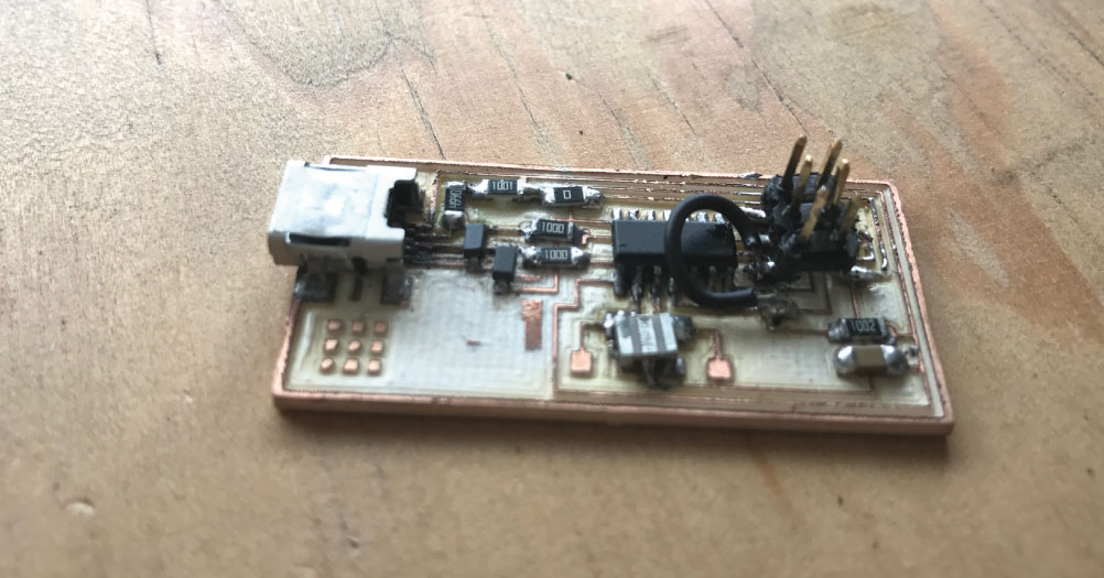
FABDUINO MODIFIED :
This board was one of the challenges of fab academy, I had to design and produce several models with eagle software, to finally get one that will work for the project and for the weekly assignments. In the Fab Lab, we had to use to design the arduino, a crystal of 16mhz with 2 consensadores and not the one of 20mhz like the original. This was due to the difficulty of obtaining the components of the indicated bookstore, and it was the one that we could obtain and had compatibility with the code.
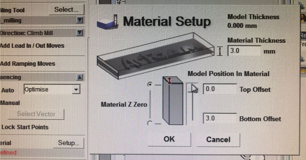
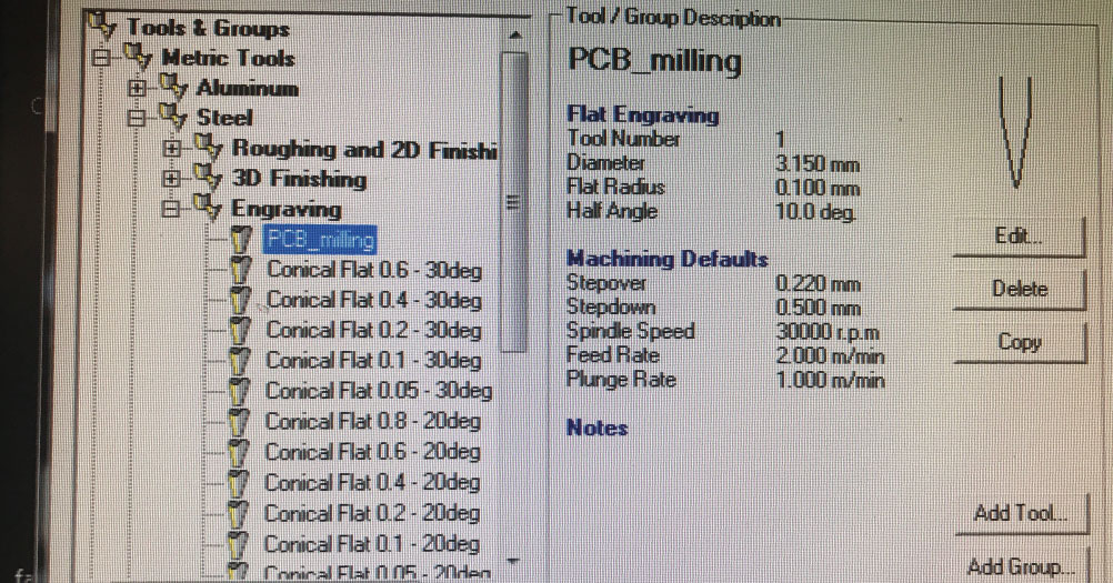
Mini CNC engraving machine :
In the Fab Lab we recibe the new Mini CNC engraving machine. Now the process it´s different like the ISP and we use news programs. Artcam will be my new best friend, it´s a program easy to use and predictive. Selecting the material with the thickness of the plate, in this case 3mm. And put the model position in top offset. 2. Choose the drills. We have generated a new configuration for milli Machine, where we indicate the measures, the type of drill and above all the stepdown, ie how much depth is going to lower the drill per pass.
Fab Academy 2017 from Montserrat .
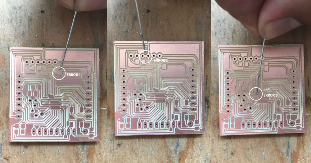
Failures:
When I made the route, I checked the connections with a power meter, and it was where I saw the connection faults between tracks, which were connected, in the three points indicated in the photos. But after designing the board so many times, I decided not to repeat the design and cut the tracks together, with a cuter. It was not the most technical solution but the fabarduino worked perfectly.
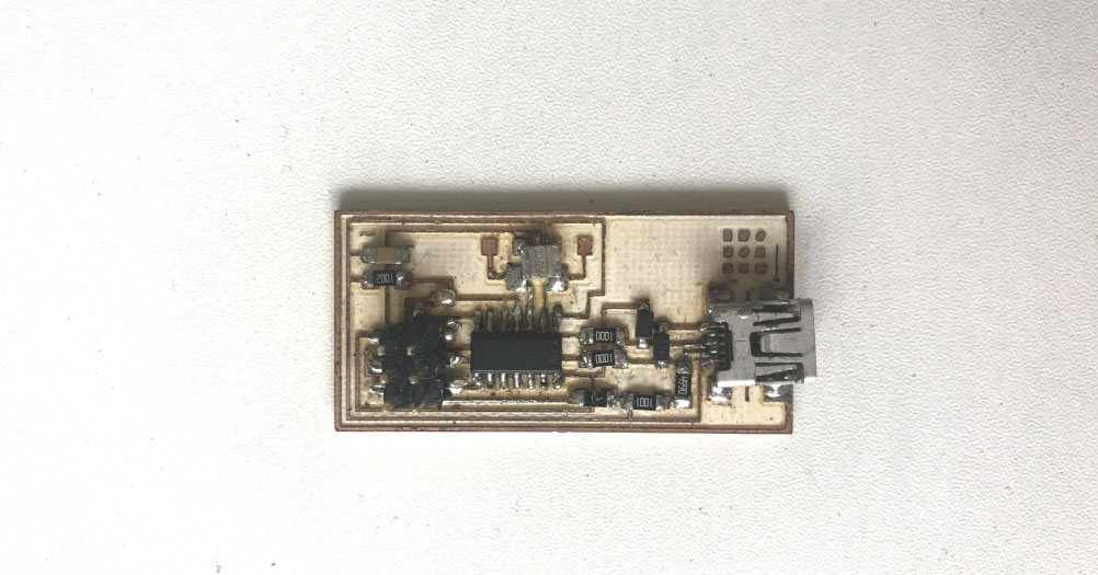
Components and results :
Cristal kit 16mhz/ resistor 499 ohm/ resistor 10k/ Led/ capacitor 1uf/ 2 capacitor 0.1 uf/ capacitor 10uf/ botton/ ATmega3284.
Final result, On the back the consoles were very close and they made connection so I had to isolate the components with tape. After having some difficulty soldering the microprocessor, I think I have obtained a good result. This compenente is important for the entire academy process, so it was important to get a good result.