


/*
* GccApplication1.c
* Created: 15/03/2017 12:00:01 p. m.
* Author : Xpere
*/
#include <avr/io.h>
#define F_cpu 1000000UL//1MHz
#include <util/delay.h>
int main(void)
{
/* Replace with your application code */
DDRA = 0b00000111;
while (1)
{
PORTA =0b00000111;
_delay_ms (200);
PORTA =0b00000000;
_delay_ms (200);
PORTA =0b00000100;
_delay_ms (200);
PORTA =0b00000000;
_delay_ms (200);
PORTA =0b00000010;
_delay_ms (200);
PORTA =0b00000000;
_delay_ms (200);
PORTA =0b00000001;
_delay_ms (200);
PORTA =0b00000000;
_delay_ms (200);
}
}
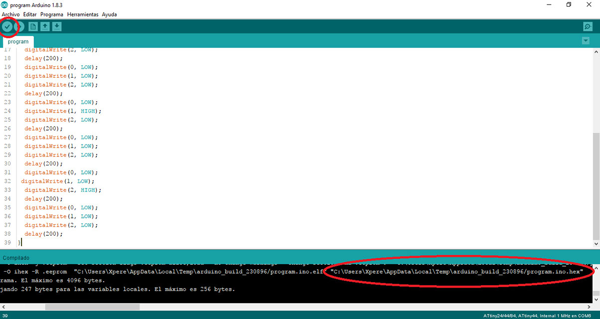
void setup() {
pinMode(0, OUTPUT);
pinMode(1, OUTPUT);
pinMode(2, OUTPUT);
}
void loop() {
digitalWrite(0, HIGH);
digitalWrite(1, HIGH);
digitalWrite(2, HIGH);
delay(200);
digitalWrite(0, LOW);
digitalWrite(1, LOW);
digitalWrite(2, LOW);
delay(200);
digitalWrite(0, HIGH);
digitalWrite(1, LOW);
digitalWrite(2, LOW);
delay(200);
digitalWrite(0, LOW);
digitalWrite(1, LOW);
digitalWrite(2, LOW);
delay(200);
digitalWrite(0, LOW);
digitalWrite(1, HIGH);
digitalWrite(2, LOW);
delay(200);
digitalWrite(0, LOW);
digitalWrite(1, LOW);
digitalWrite(2, LOW);
delay(200);
digitalWrite(0, LOW);
digitalWrite(1, LOW);
digitalWrite(2, HIGH);
delay(200);
digitalWrite(0, LOW);
digitalWrite(1, LOW);
digitalWrite(2, LOW);
delay(200);
}