i want to make a board that will have a solid state relay or power switch CPC1964B, the attiny2313 microcontroller and a serial port where i will connect a HC05 bluetooth module. with this board i pretend to make a bluetooth lamp that will be controlled by an android smartphone using an app
for this week assignment i will design and build the board and then write the program to do the ligthbulb blink to test the AC12o volts output. as i did in the previous weeks i will design the circuit board in eagle, i will program it using arduino ide and the icsp USBasp conected in the icsp port in the board. here i will show you the data sheet of the solid state relay
i make the board using the modela milling and i solder all the components, i test the board with a 9 volt batterie, then i connect the circuit of a recycled smartphone charger to convert the 120 VAC into 5 VDC used in the board. after reading the attiny 2313B datasheet i found that the pin i used to control the power switch is the 9 pin so i use the blinking example code to test my board this is the modified code the 50 ms is changed because the external 20 MHz cristal multiplies the delay by 20, so for one second i have to write 50 ms here is the code. this is the final result one problem that i found was when i try to measure the continuity between the pins, i tried to measure to make sure that the circuit work before connecting the light bulb and the ac voltage. even if the circuit worked and blinked the pin in the attiny i couldn't see it in the output with the multimeter. i decided to connect the ac voltage to the circuit input and i measure the ac voltage at the output, it worked and it switched the 120 ac volts. at the end i connect the light bulb and it blinked . you can follow my progress and see how i did the connection of the board with the bluethoot module and how it works in the week 15 networking and communications assignment. you can go to the week 15 webpage clicking here you can download the eagle schematic file here
ABOUT ME
Add an output device to a microcontroller board you've designed and program it to do something
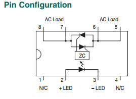
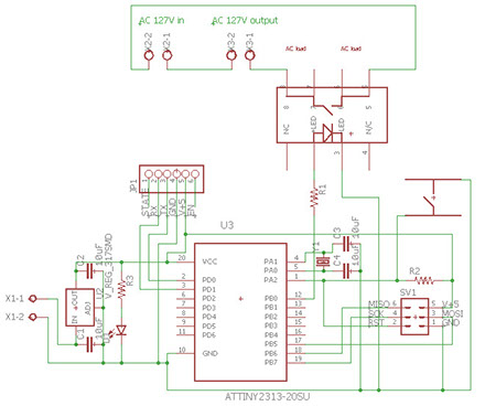
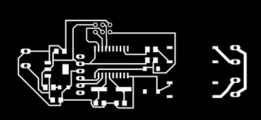
here is the pin configuration as we see in the diagram this switch activates when the internal led is powered on and the pins 7 and 8 acts like a switch and let pass the power closing the circuit. knowing the way the circuit work we can now make the schematic and the board design here i will show how is the final design in eagle
you can download the eagle board file here NOTE: if you can´'t download directly by clicking on the button you have to right click on the here button and then click on "save link as" option to download the file.
ASSIGNMENTS
week ten outputs

void setup() {

  pinMode(9, OUTPUT);

}

void loop() {

  digitalWrite(9, HIGH);

  delay(50);

  digitalWrite(9, LOW);

  delay(50);

}

FINAL PROJECT
you can download the arduino program here
CONTACT
you can download the hex file here
Carlos Pérez Ramírez